Page 1360 of 2543
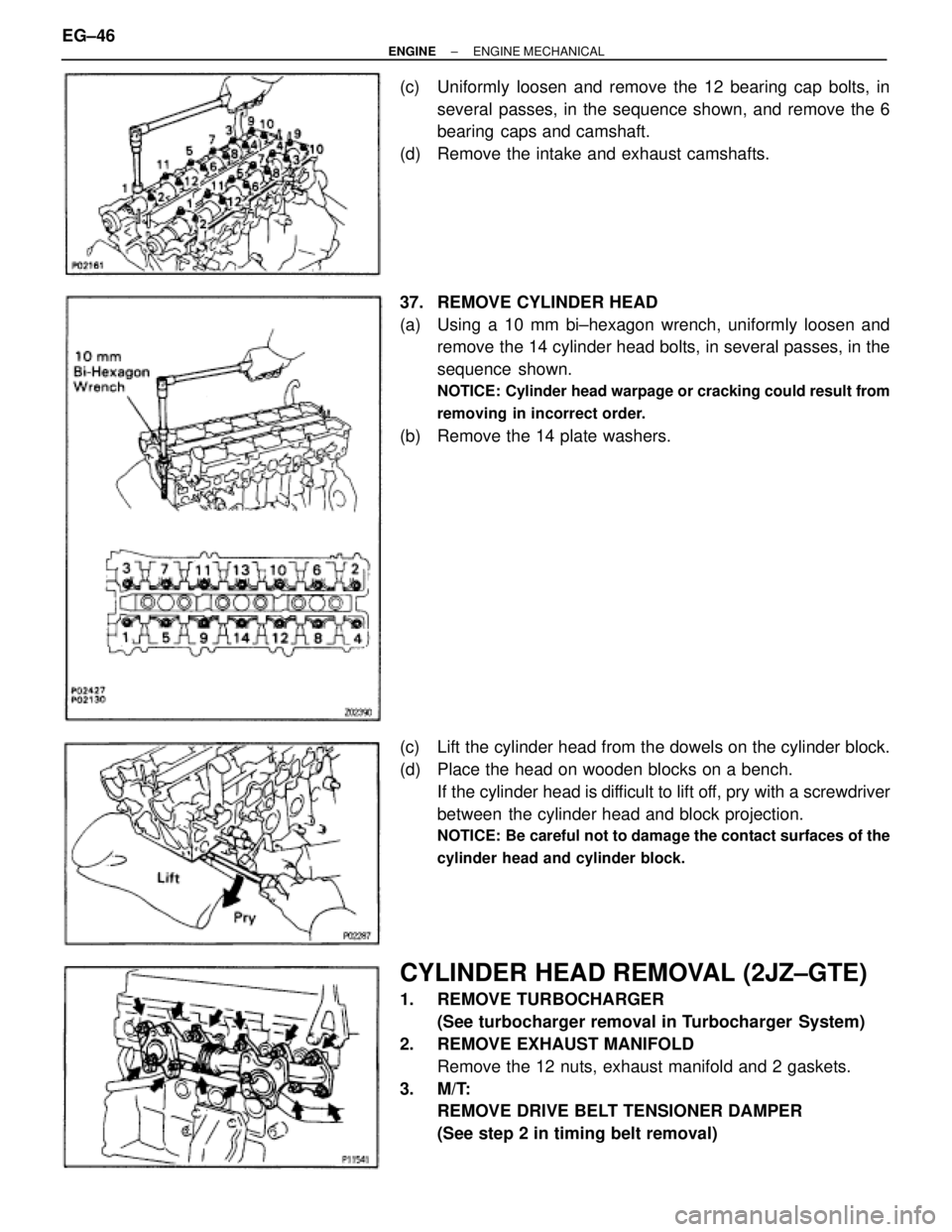
(c) Uniformly loosen and remove the 12 bearing cap bolts, in
several passes, in the sequence shown, and remove the 6
bearing caps and camshaft.
(d) Remove the intake and exhaust camshafts.
37. REMOVE CYLINDER HEAD
(a) Using a 10 mm bi±hexagon wrench, uniformly loosen and
remove the 14 cylinder head bolts, in several passes, in the
sequence shown.
NOTICE: Cylinder head warpage or cracking could result from
removing in incorrect order.
(b) Remove the 14 plate washers.
(c) Lift the cylinder head from the dowels on the cylinder block.
(d) Place the head on wooden blocks on a bench.
If the cylinder head is difficult to lift off, pry with a screwdriver
between the cylinder head and block projection.
NOTICE: Be careful not to damage the contact surfaces of the
cylinder head and cylinder block.
CYLINDER HEAD REMOVAL (2JZ±GTE)
1. REMOVE TURBOCHARGER
(See turbocharger removal in Turbocharger System)
2. REMOVE EXHAUST MANIFOLD
Remove the 12 nuts, exhaust manifold and 2 gaskets.
3. M/T:
REMOVE DRIVE BELT TENSIONER DAMPER
(See step 2 in timing belt removal) EG±46
± ENGINEENGINE MECHANICAL
Page 1362 of 2543
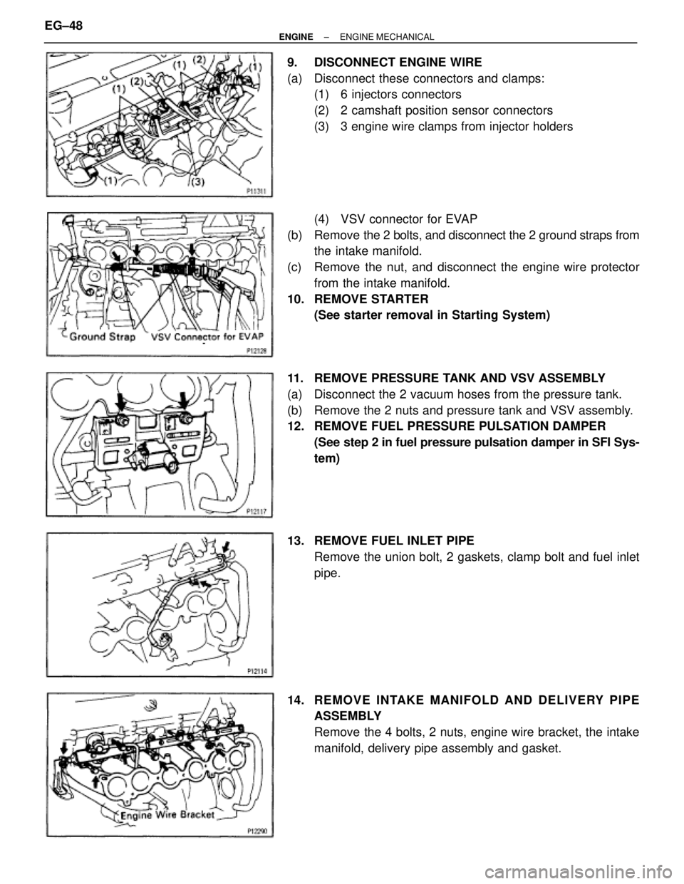
9. DISCONNECT ENGINE WIRE
(a) Disconnect these connectors and clamps:
(1) 6 injectors connectors
(2) 2 camshaft position sensor connectors
(3) 3 engine wire clamps from injector holders
(4) VSV connector for EVAP
(b) Remove the 2 bolts, and disconnect the 2 ground straps from
the intake manifold.
(c) Remove the nut, and disconnect the engine wire protector
from the intake manifold.
10. REMOVE STARTER
(See starter removal in Starting System)
11. REMOVE PRESSURE TANK AND VSV ASSEMBLY
(a) Disconnect the 2 vacuum hoses from the pressure tank.
(b) Remove the 2 nuts and pressure tank and VSV assembly.
12. REMOVE FUEL PRESSURE PULSATION DAMPER
(See step 2 in fuel pressure pulsation damper in SFI Sys-
tem)
13. REMOVE FUEL INLET PIPE
Remove the union bolt, 2 gaskets, clamp bolt and fuel inlet
pipe.
14. RE MO V E INTAKE MANIFO LD AND DE LIV E RY PIP E
ASSEMBLY
Remove the 4 bolts, 2 nuts, engine wire bracket, the intake
manifold, delivery pipe assembly and gasket. EG±48
± ENGINEENGINE MECHANICAL
Page 1363 of 2543
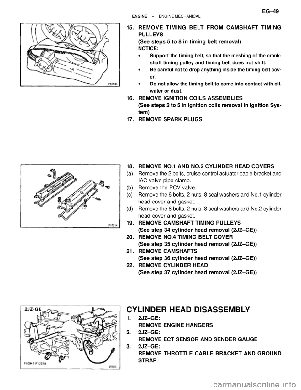
15. REMOVE TIMING BELT FROM CAMSHAFT TIMING
PULLEYS
(See steps 5 to 8 in timing belt removal)
NOTICE:
wSupport the timing belt, so that the meshing of the crank-
shaft timing pulley and timing belt does not shift.
wBe careful not to drop anything inside the timing belt cov-
er.
wDo not allow the timing belt to come into contact with oil,
water or dust.
16. REMOVE IGNITION COILS ASSEMBLIES
(See steps 2 to 5 in ignition coils removal in Ignition Sys-
tem)
17. REMOVE SPARK PLUGS
18. REMOVE NO.1 AND NO.2 CYLINDER HEAD COVERS
(a) Remove the 2 bolts, cruise control actuator cable bracket and
IAC valve pipe clamp.
(b) Remove the PCV valve.
(c) Remove the 6 bolts, 2 nuts, 8 seal washers and No.1 cylinder
head cover and gasket.
(d) Remove the 6 bolts, 2 nuts, 8 seal washers and No.2 cylinder
head cover and gasket.
19. REMOVE CAMSHAFT TIMING PULLEYS
(See step 34 cylinder head removal (2JZ±GE))
20. REMOVE NO.4 TIMING BELT COVER
(See step 35 cylinder head removal (2JZ±GE))
21. REMOVE CAMSHAFTS
(See step 36 cylinder head removal (2JZ±GE))
22. REMOVE CYLINDER HEAD
(See step 37 cylinder head removal (2JZ±GE))
CYLINDER HEAD DISASSEMBLY
1. 2JZ±GE:
REMOVE ENGINE HANGERS
2. 2JZ±GE:
REMOVE ECT SENSOR AND SENDER GAUGE
3. 2JZ±GE:
REMOVE THROTTLE CABLE BRACKET AND GROUND
STRAP
± ENGINEENGINE MECHANICALEG±49
Page 1364 of 2543
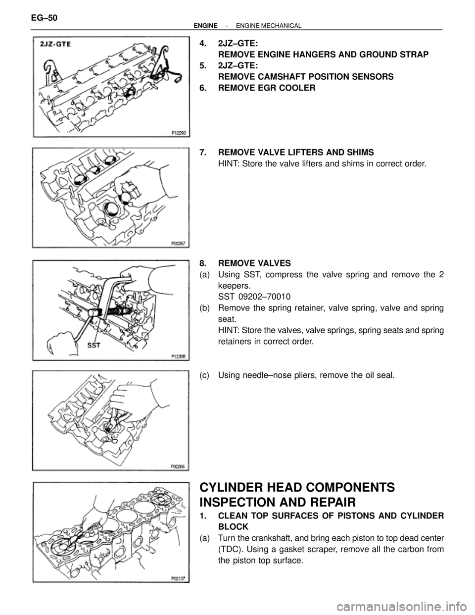
4. 2JZ±GTE:
REMOVE ENGINE HANGERS AND GROUND STRAP
5. 2JZ±GTE:
REMOVE CAMSHAFT POSITION SENSORS
6. REMOVE EGR COOLER
7. REMOVE VALVE LIFTERS AND SHIMS
HINT: Store the valve lifters and shims in correct order.
8. REMOVE VALVES
(a) Using SST, compress the valve spring and remove the 2
keepers.
SST 09202±70010
(b) Remove the spring retainer, valve spring, valve and spring
seat.
HINT: Store the valves, valve springs, spring seats and spring
retainers in correct order.
(c) Using needle±nose pliers, remove the oil seal.
CYLINDER HEAD COMPONENTS
INSPECTION AND REPAIR
1. CLEAN TOP SURFACES OF PISTONS AND CYLINDER
BLOCK
(a) Turn the crankshaft, and bring each piston to top dead center
(TDC). Using a gasket scraper, remove all the carbon from
the piston top surface. EG±50
± ENGINEENGINE MECHANICAL
Page 1371 of 2543
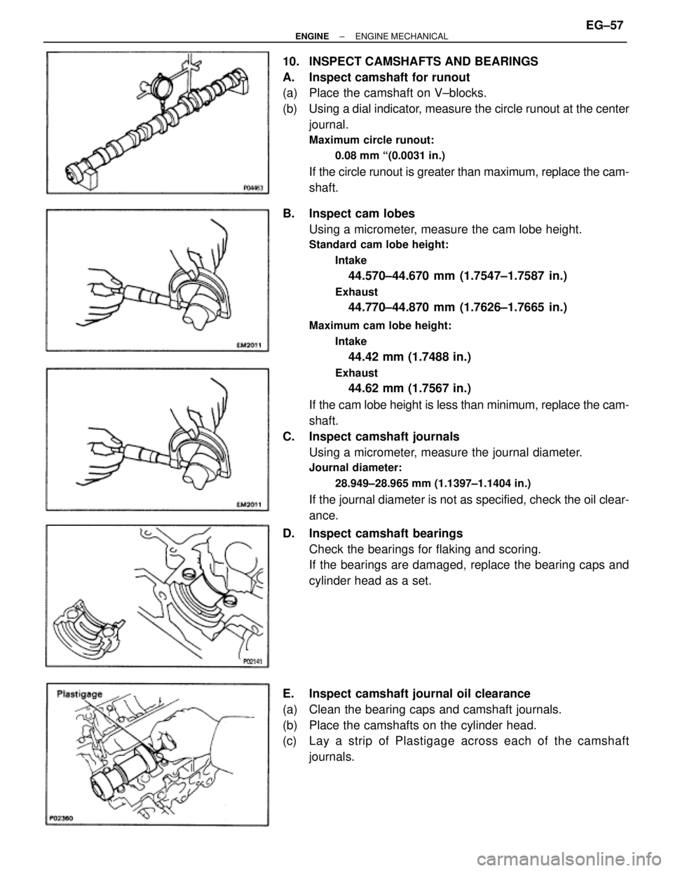
10. INSPECT CAMSHAFTS AND BEARINGS
A. Inspect camshaft for runout
(a) Place the camshaft on V±blocks.
(b) Using a dial indicator, measure the circle runout at the center
journal.
Maximum circle runout:
0.08 mm ª(0.0031 in.)
If the circle runout is greater than maximum, replace the cam-
shaft.
B. Inspect cam lobes
Using a micrometer, measure the cam lobe height.
Standard cam lobe height:
Intake
44.570±44.670 mm (1.7547±1.7587 in.)
Exhaust
44.770±44.870 mm (1.7626±1.7665 in.)
Maximum cam lobe height:
Intake
44.42 mm (1.7488 in.)
Exhaust
44.62 mm (1.7567 in.)
If the cam lobe height is less than minimum, replace the cam-
shaft.
C. Inspect camshaft journals
Using a micrometer, measure the journal diameter.
Journal diameter:
28.949±28.965 mm (1.1397±1.1404 in.)
If the journal diameter is not as specified, check the oil clear-
ance.
D. Inspect camshaft bearings
Check the bearings for flaking and scoring.
If the bearings are damaged, replace the bearing caps and
cylinder head as a set.
E. Inspect camshaft journal oil clearance
(a) Clean the bearing caps and camshaft journals.
(b) Place the camshafts on the cylinder head.
(c) Lay a strip of Plastigage across each of the camshaft
journals.
± ENGINEENGINE MECHANICALEG±57
Page 1372 of 2543
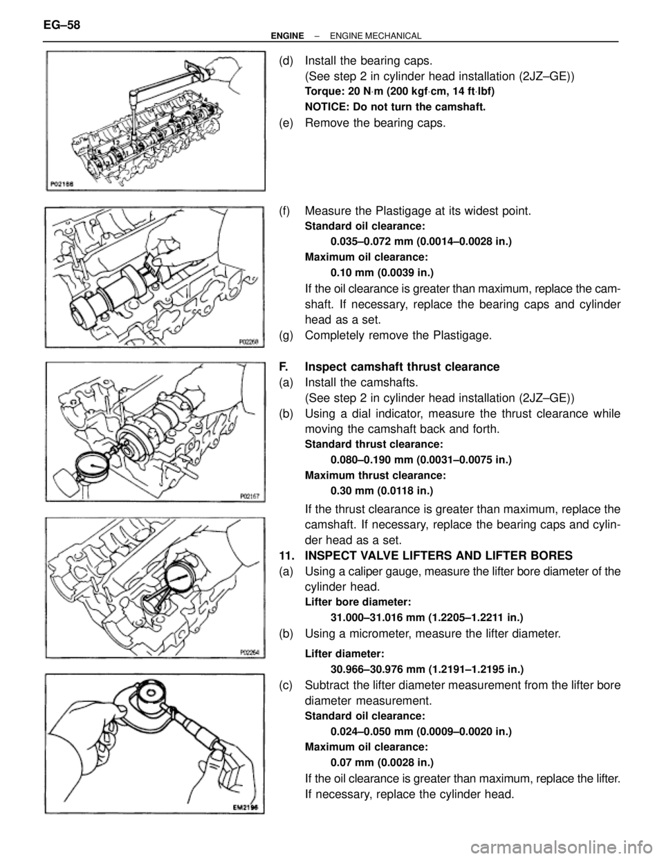
(d) Install the bearing caps.
(See step 2 in cylinder head installation (2JZ±GE))
Torque: 20 NVm (200 kgfVcm, 14 ftVlbf)
NOTICE: Do not turn the camshaft.
(e) Remove the bearing caps.
(f) Measure the Plastigage at its widest point.
Standard oil clearance:
0.035±0.072 mm (0.0014±0.0028 in.)
Maximum oil clearance:
0.10 mm (0.0039 in.)
If the oil clearance is greater than maximum, replace the cam-
shaft. If necessary, replace the bearing caps and cylinder
head as a set.
(g) Completely remove the Plastigage.
F. Inspect camshaft thrust clearance
(a) Install the camshafts.
(See step 2 in cylinder head installation (2JZ±GE))
(b) Using a dial indicator, measure the thrust clearance while
moving the camshaft back and forth.
Standard thrust clearance:
0.080±0.190 mm (0.0031±0.0075 in.)
Maximum thrust clearance:
0.30 mm (0.0118 in.)
If the thrust clearance is greater than maximum, replace the
camshaft. If necessary, replace the bearing caps and cylin-
der head as a set.
11. INSPECT VALVE LIFTERS AND LIFTER BORES
(a) Using a caliper gauge, measure the lifter bore diameter of the
cylinder head.
Lifter bore diameter:
31.000±31.016 mm (1.2205±1.2211 in.)
(b) Using a micrometer, measure the lifter diameter.
Lifter diameter:
30.966±30.976 mm (1.2191±1.2195 in.)
(c) Subtract the lifter diameter measurement from the lifter bore
diameter measurement.
Standard oil clearance:
0.024±0.050 mm (0.0009±0.0020 in.)
Maximum oil clearance:
0.07 mm (0.0028 in.)
If the oil clearance is greater than maximum, replace the lifter.
If necessary, replace the cylinder head. EG±58
± ENGINEENGINE MECHANICAL
Page 1376 of 2543
8. 2JZ±GTE:
INSTALL CAMSHAFT POSITION SENSORS
Install the gasket and sensor with the 2 bolts.
Torque: 8.8 NVm (90 kgfVcm, 78 in.Vlbf)
9. 2JZ±GTE:
INSTALL ENGINE HANGERS AND GROUND STRAP
Torque: 39 NVm (400 kgfVcm, 29 ftVlbf)
CYLINDER HEAD INSTALLATION
(2JZ±GE)
1. INSTALL CYLINDER HEAD
A. Place cylinder head on cylinder block
(a) Place a new cylinder head gasket in position on the cylinder
block.
NOTICE: Be sure to install it correctly.
(b) Place the cylinder head in position on the cylinder head
gasket.
B. Install cylinder head bolts
HINT:
wThe cylinder head bolts are tightened in 2 progressive
steps (steps (c) and (f)).
wIf any of bolts break or deform, replace them.
(a) Apply a light coat of engine oil on the threads and under the
heads of the cylinder head bolts.
(b) Install the 14 plate washers to each cylinder head bolt.
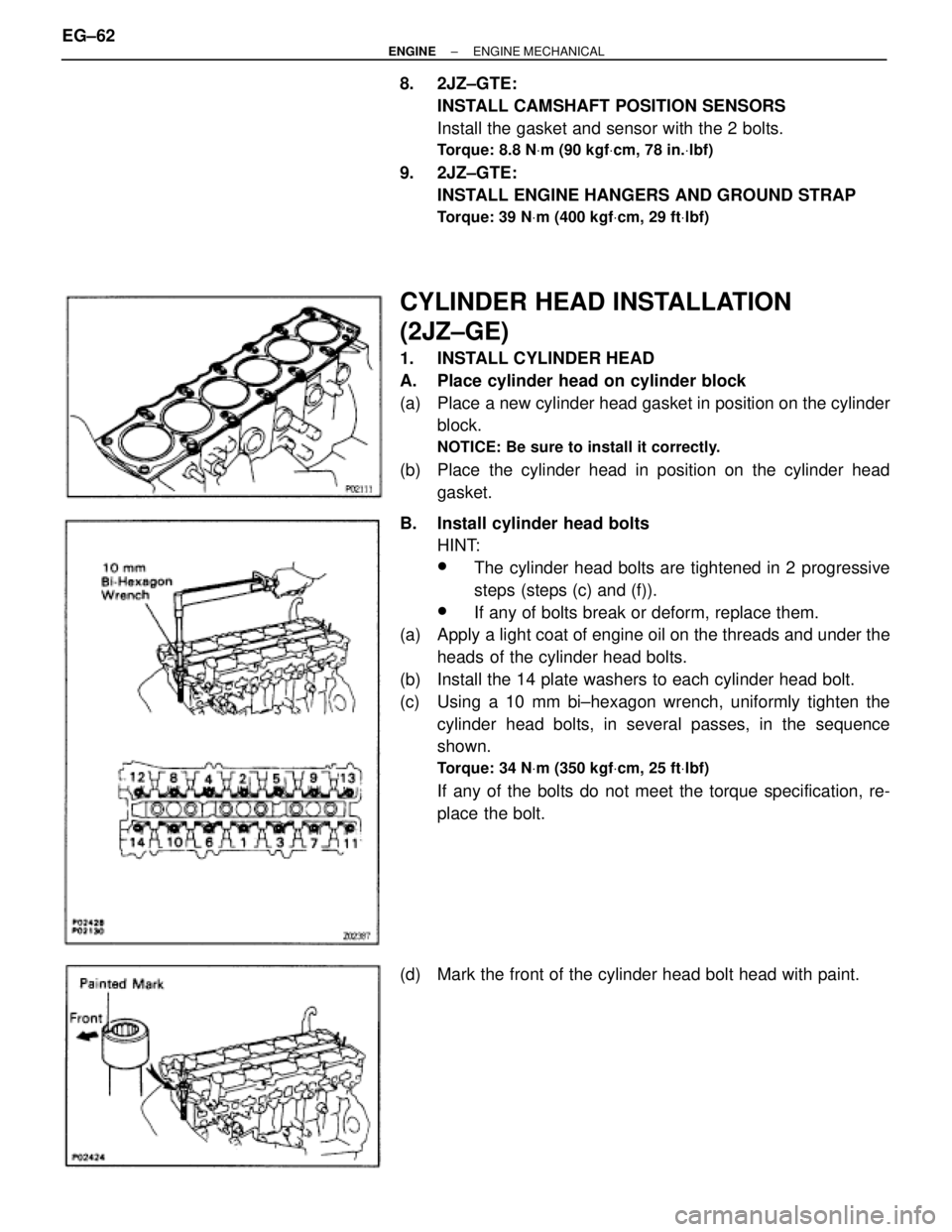
(c) Using a 10 mm bi±hexagon wrench, uniformly tighten the
cylinder head bolts, in several passes, in the sequence
shown.
Torque: 34 NVm (350 kgfVcm, 25 ftVlbf)
If any of the bolts do not meet the torque specification, re-
place the bolt.
(d) Mark the front of the cylinder head bolt head with paint. EG±62
± ENGINEENGINE MECHANICAL
Page 1377 of 2543
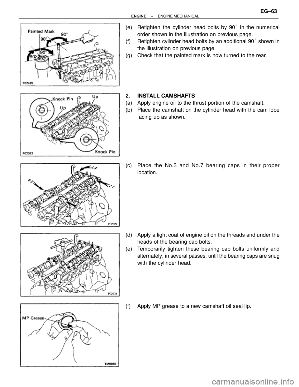
(e) Retighten the cylinder head bolts by 90° in the numerical
order shown in the illustration on previous page.
(f) Retighten cylinder head bolts by an additional 90° shown in
the illustration on previous page.
(g) Check that the painted mark is now turned to the rear.
2. INSTALL CAMSHAFTS
(a) Apply engine oil to the thrust portion of the camshaft.
(b) Place the camshaft on the cylinder head with the cam lobe
facing up as shown.
(c) Place the No.3 and No.7 bearing caps in their proper
location.
(d) Apply a light coat of engine oil on the threads and under the
heads of the bearing cap bolts.
(e) Temporarily tighten these bearing cap bolts uniformly and
alternately, in several passes, until the bearing caps are snug
with the cylinder head.
(f) Apply MP grease to a new camshaft oil seal lip.
± ENGINEENGINE MECHANICALEG±63