Page 1141 of 2543
 Quickly race the engine 5 times to 4,000 rpm.
(b) Remove the spark plug.
(c) Visually check the spark plug.
If the electrode is dry...OK
If the electrode is wet...Proceed to step")
Simple Method:
(a) Quickly race the engine 5 times to 4,000 rpm.
(b) Remove the spark plug.
(c) Visually check the spark plug.
If the electrode is dry...OK
If the electrode is wet...Proceed to step 4
(d) Reinstall the spark plug.
3. REMOVE SPARK PLUGS
Using a 16 mm plug wrench, remove the 6 spark plugs.
4. VISUALLY INSPECT SPARK PLUGS
Check the spark plug for thread damage and insulator dam-
age.
If abnormal, replace the spark plug.
Recommended spark plug:
ND
PK16R11
NGK
BKR5EP11
5. INSPECT ELECTRODE GAP
Maximum electrode gap for used spark plug:
1.3 mm (0.051 in.)
If the gap is greater than maximum, replace the spark plug.
Correct electrode gap for new spark plug:
1.1 mm (0.043 in.)
NOTICE: If adjusting the gap of a new spark plug, bend only
the base of the ground electrode. Do not touch the tip. Never
attempt to adjust the gap on the used plug.
6. CLEAN SPARK PLUGS
If the electrode has traces of wet carbon, allow it to dry and
then clean with a spark plug cleaner.
Air pressure:
Below 588 kPa (6 kgfVcm
2, 85 psi)
Duration:
20 seconds or less
HINT: If there are traces of oil, remove it with gasoline before
using the spark plug cleaner.
7. REINSTALL SPARK PLUGS
Torque: 18 NVm (180 kgfVcm, 13 ftVlbf)
8. RECONNECT HIGH±TENSION CORDS TO SPARK
PLUGS IG±6
± IGNITION SYSTEM(2JZ±GE)
Page 1152 of 2543
(b) Check that the timing marks of the camshaft timing pulleys
and No.4 timing belt cover are aligned.
If not, turn the crankshaft 1 revolution (360°) and align the
mark as above.
3. INSTALL DISTRIBUTOR
(a) Install a new O±ring to the distributor housing.
(b) Apply a light coat of engine oil on the O±ring.
(c) Align the marks of the drive gear and distributor housing.
(d) Insert the distributor, aligning the protrusion of the flange with
that of the stud bolt on the cylinder head.
(e) Install the distributor with the nut. Lightly tighten the nut.
4. REINSTALL NO.3 TIMING BELT COVER
5. CONNECT HIGH±TENSION CORDS TO DISTRIBUTOR
Connect the 7 high±tension cords to the distributor.
Firing order:
1 ± 5 ± 3 ± 6 ± 2 ± 4
6. CONNECT DISTRIBUTOR CONNECTOR
7. ADJST IGNITION TIMING
(See ignition timing inspection and adjustment)
± IGNITION SYSTEM(2JZ±GE)IG±17
Page 1154 of 2543
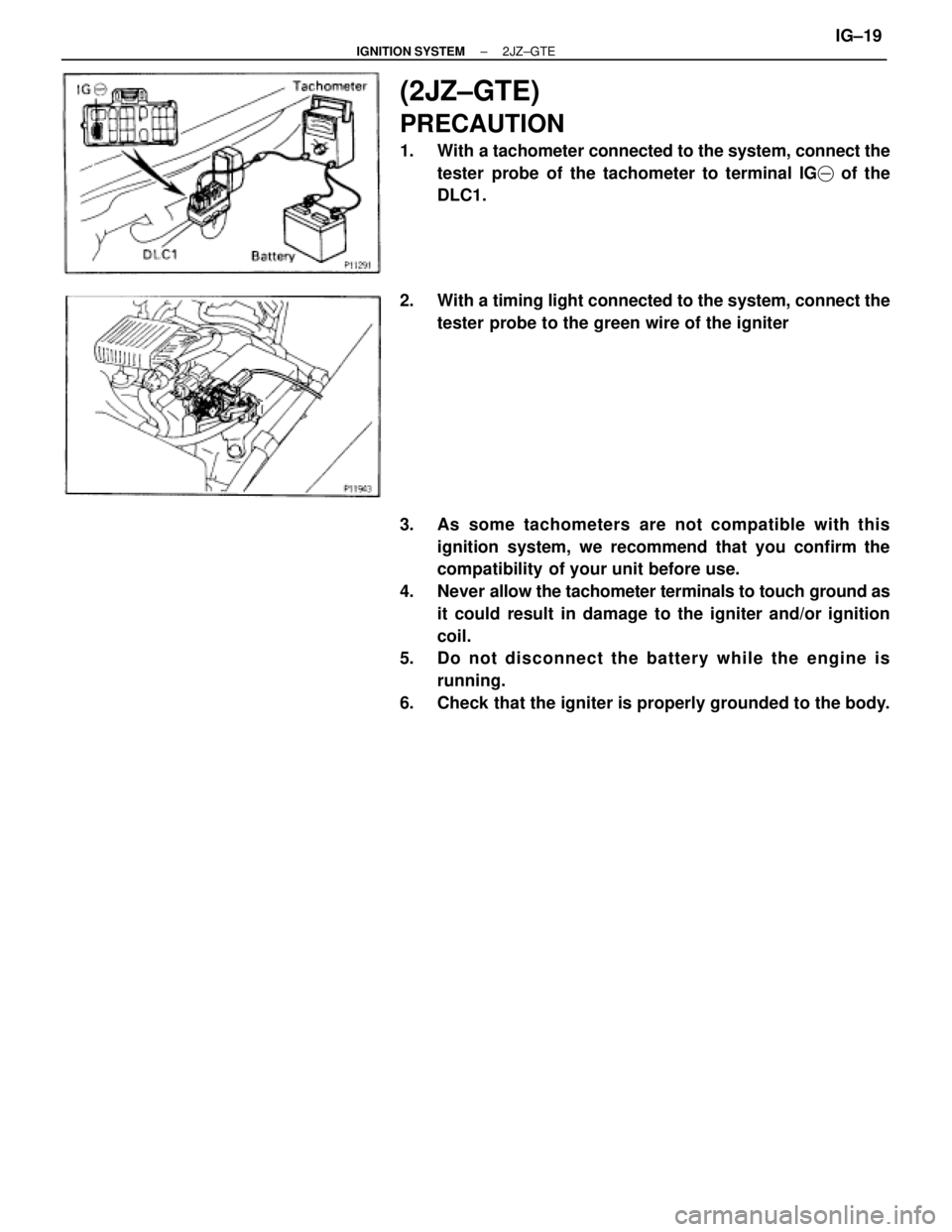
(2JZ±GTE)
PRECAUTION
1. With a tachometer connected to the system, connect the
tester probe of the tachometer to terminal IG� of the
DLC1.
2. With a timing light connected to the system, connect the
tester probe to the green wire of the igniter
3. As some tachometers are not compatible with this
ignition system, we recommend that you confirm the
compatibility of your unit before use.
4. Never allow the tachometer terminals to touch ground as
it could result in damage to the igniter and/or ignition
coil.
5. Do not disconnect the battery while the engine is
running.
6. Check that the igniter is properly grounded to the body.
± IGNITION SYSTEM2JZ±GTEIG±19
Page 1156 of 2543
 Remove the ignition coil. (See ignition coil removal)
(b) Remove the spark plug.
(c) Install the spark plug to the ignition coil, and c")
ON±VEHICLE INSPECTION
SPARK TEST
CHECK THAT SPARK OCCURS
(a) Remove the ignition coil. (See ignition coil removal)
(b) Remove the spark plug.
(c) Install the spark plug to the ignition coil, and connect the
ignition coil connecter.
(d) Ground the spark plug.
(e) Check if spark occurs while engine is being cranked.
HINT: To prevent gasoline from being injected from injectors
during this test, crank the engine for no more than 1±2 se-
conds at time.
If the spark does not occur, do the test as follows:
SPARK TEST
CHECK CONNECTION OF IGNITION COIL, IGNITER
CHECK POWER SUPPLY TO IGNITION COIL AND
IGNITER
1. Turn ignition switch to ON.
2. Check that there is battery voltage at
ignition coil positive (+) terminal.
CHECK RESISTANCE OF IGNITION COIL(See page IG±23)Resistance: Cold Hot
Primary 0.54 ± 0.84 �0.68 ± 0.98 �
CHECK RESISTANCE OF CAMSHAFT AND
CRANKSHAFT POSITION SENSOR
(See page IG±24)Resistance: Cold Hot
NIPPONDENSO 835 ± 1,400 �1,060 ± 1,645 �
AISAN 985 ± 1,600 �1,265 ± 1,890 �
CHECK IGT SIGNAL FROM ECM(See page EG±519)
TRY ANOTHER IGNITER
Connect securely.
Check wiring between ignition switch
to ignition coil and igniter.
Replace the ignition coil.
Replace the camshaft and crankshaft position
sensor.
Check wiring between ECM,and igniter, and
then try another ECM.
ADJUST IGNITION TIMING
(See ignition timing inspection and adjustment)
± IGNITION SYSTEM2JZ±GTEIG±21
Page 1157 of 2543
.
1")
SPARK PLUGS INSPECTION
NOTICE:
wNever use a wire brush for cleaning.
wNever attempt to adjust the electrode gap on used a spark
plug.
wSpark plugs should be replaced every 100,000 km (60,000
miles).
1. REMOVE IGNITION COILS ASSEMBLIES
(See ignition coils removal)
2. INSPECT ELECTRODE
Using a megger (insulation resistance meter), measure the
insulation resistance.
Standard correct insulation resistance:
10 M � or more
If the resistance is less than specified, proceed to step 4.
HINT: If a megger is not available, the following simple meth-
od of inspection provides fairly accurate results.
Simple Method:
(a) Quickly race the engine 5 times to 4,000 rpm.
(b) Remove the spark plug.
(c) Visually check the spark plug.
If the electrode is dry...OK
If the electrode is wet...Proceed to step 4
(d) Reinstall the spark plug.
3. REMOVE SPARK PLUGS
4. VISUALLY INSPECT SPARK PLUGS
Check the spark plug for thread damage and insulator dam-
age.
If abnormal, replace the spark plug.
Recommended spark plug:
ND
PK20R11
NGK
BKR6EP11
5. INSPECT ELECTRODE GAP
Maximum electrode gap for used spark plug:
1.3 mm (0.051 in.)
Correct electrode gap for new spark plug:
1.1 mm (0.043 in.)
NOTICE: If adjusting the gap of a new spark plug, bend only
the base of the ground electrode. Do not touch the tip. Never
attempt to adjust the gap on the used plug.
IG±22± IGNITION SYSTEM(2JZ±GTE)
Page 1161 of 2543
IGNITION COIL
COMPONENTS FOR REMOVAL AND
INSTALLATION
IGNITION COILS REMOVAL
Installation is in the reverse order of removal.
1. REMOVE NO.3 TIMING BELT COVER
(a) Remove the oil filler cap.
(b) Using a 5 mm hexagon wrench, remove the 10 bolts, belt
cover and gasket.
2. REMOVE PCV HOSES
Remove the 2 PCV hoses.
3. DISCONNECT IGNITION COIL CONNECTORS
(a) Disconnect the engine wire from the 6 clamps on the ignition
coils.
(b) Disconnect the 6 ignition coil connectors. IG±26
± IGNITION SYSTEM2JZ±GTE
Page 1166 of 2543

SERVICE SPECIFICATIONS
SERVICE DATA
����� �����Firing order����������������� �����������������±���������������� ����������������1 ± 5 ± 3 ± 6 ± 2 ± 4����� �
���� �
���� �
���� �����
Spark plug����������������� �
���������������� �
���������������� �
���������������� �����������������
Recommended spark plug ND
NGK
Correct electrode gap for new plug
Maximum electrode gap for used plug���������������� �
��������������� �
��������������� �
��������������� ����������������
PK20R11
BKR6EP11
1.1 mm (0.043 in.)
1.3 mm (0.051 in.)
����� �
���� �����
Ignition coil����������������� �
���������������� �����������������
Primary coil resistance at cold
at hot���������������� �
��������������� ����������������
0.54±0.84 �
0.68±0.98 �
����� �
���� �
���� �
���� �����
Camshaft
position
sensor����������������� �
���������������� �
���������������� �
���������������� �����������������
Resistance at cold
at hot���������������� �
��������������� �
��������������� �
��������������� ����������������
835±1,400 � for NIPPONDENSO
985±1,600 � for AISAN
1,060±1,645 � for NIPPONDENSO
1,265±1,890 � for AISAN
����� �
���� �
���� �
���� �����
Crankshaft
position
sensor����������������� �
���������������� �
���������������� �
���������������� �����������������
Resistance at cold
at hot���������������� �
��������������� �
��������������� �
��������������� ����������������
835±1,400 � for NIPPONDENSO
985±1,600 � for AISAN
1,060±1,645 � for NIPPONDENSO
1,265±1,890 � for AISAN
TORQUE SPECIFICATIONS
�������������������� ��������������������Part tightened������ ������NVm������ ������kgfVcm������� �������ftVlbf�������������������� ��������������������Ignition coil bracket x Cylinder head������ ������8.8������ ������90������� �������78 in.Vlbf�������������������� �
������������������� ��������������������Ignition coil x Ignition coil bracket������ �
����� ������2.5������ �
����� ������35������� �
������ �������3.4 in.Vlbf
�������������������� ��������������������Camshaft position sensor x Cylinder head������ ������8.8������ ������90������� �������78 in.Vlbf
�������������������� ��������������������Engine hanger x Cylinder head������ ������39������ ������400������� �������29
�������������������� ��������������������Crankshaft position sensor x Oil pump������ ������8.8������ ������90������� �������78 in.Vlbf
± IGNITION SYSTEM2JZ±GTEIG±31
Page 1182 of 2543

Wire Harness and Connector
The SRS wire harness is integrated with the cowl wire har-
ness assembly and floor wire harness assembly. The wires
for the SRS wire harness are encased in a yellow corrugated
tube. All the connectors for the system are also a standard
yellow color. If the SRS wire harness becomes disconnected
or the connector becomes broken due to an accident, etc.,
repair or replace it as shown on page RS±36.
FOR VEHICLES EQUIPPED WITH A CATALYTIC CONVERTER
CAUTION: If large amounts of unburned gasoline flow into the converter, it may overheat and create a fire
hazard. To prevent this, observe the following precautions and explain them to your customer.
1. Use only unleaded gasoline.
2. Avoid prolonged idling.
Avoid running the engine at idle speed for more than 20 minutes.
3. Avoid spark jump test.
(a) Perform spark jump test only when absolutely necessary. Perform this test as rapidly as possible.
(b) While testing, never race the engine.
4. Avoid prolonged engine compression measurement.
Engine compression tests must be done as rapidly as possible.
5. Do not run engine when fuel tank is nearly empty.
This may cause the engine to misfire and create an extra load on the converter.
6. Avoid coasting with ignition turned off and prolonged braking.
7. Do not dispose of used catalyst along with parts contaminated with gasoline or oil.
± INTRODUCTIONPRECAUTIONIN±15
 Check that the timing marks of the camshaft timing pulleys
and No.4 timing belt cover are aligned.
If not, turn the crankshaft 1 revolution (360°) and align the
mark as above.
3. INSTALL DISTRIB")
 Remove the oil filler cap.
(b) Usi")