Page 168 of 2543
A340E (2JZ-GTE) AUTOMATIC TRANSMISSIONCOMPONENT PARTS REMOVAL -
AT-20
(b) Using SST, remove the snap ring.
SST 09350-30020 (09350-07060)
(c) Using SST, remove the overdrive support assembly.
SST 09350-30020 (09350-07020)
(d) Remove the assembled bearing and races from the over-
drive support.
28. CHECK PISTON ROD STROKE OF SECOND COAST
BRAKE
(a) Using a waterproof pen, place a mark on the second
coast brake piston rod.
(b) Using SST, measure the stroke while applying and releas-
ing compressed air (392-784 kPa, 4-8 kgf/cm
2 or 57-114
psi).
SST 09240-00020
Piston rod stroke:
1.0 - 2.0 mm (0.039 - 0.079 in.)
If the values are non-standard, inspect the brake band.
Page 410 of 2543
6. REMOVE REAR CENTER FLOOR CROSSMEMBER
BRACE
Normal Roof:
Remove the 4 bolts and center floor crossmember brace.
Torque: 13 NVm (130 kgfVcm, 9 ftVlbf)
Sport Roof:
Remove the 6 bolts and center floor crossmember brace.
Torque: 13 NVm (130 kgfVcm, 9 ftVlbf)
7. REMOVE PROPELLER SHAFT
(See page PR±7)
8. REMOVE SHIFT CONTROL ROD
(a) Remove the nut from shift lever.
INSTALLATION HINT: Inspect and adjust the park/ neutral
position switch.
(b) Remove the nut and control rod with the control shaft lever.
Torque: 16 NVm (160 kgfVcm, 12 ftVlbf)
9. DISCONNECT THESE CONNECTORS
w No.1 vehicle speed sensor connector
w No.2 vehicle speed sensor connector
w Solenoid wire connector
w Sensor cover
w A/T fluid temp. sensor connector
w Park/neutral position switch connector
10. DISCONNECT 3 WIRE CLAMPS FROM THE BRACKET
ON TRANSMISSION AT1±24
± AT340E (2JZ±GE) AUTOMATIC TRANSMISSIONASSEMBLY REMOVAL AND INSTALLATION
Page 811 of 2543

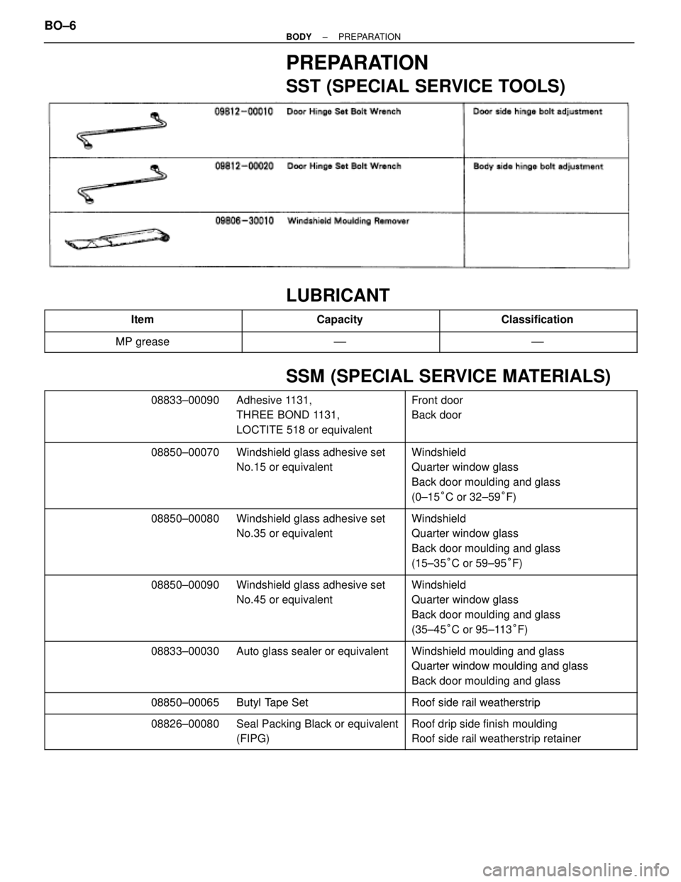
PREPARATION
SST (SPECIAL SERVICE TOOLS)
LUBRICANT
������������� �������������Item������������ ������������Capacity������������� �������������Classification
�������������MP grease±±±±������������� �������������MP grease±±±±
SSM (SPECIAL SERVICE MATERIALS)
���������������������� �
��������������������� �
��������������������� ����������������������
08833±00090 Adhesive 1131,
THREE BOND 1131,
LOCTITE 518 or equivalent��������������� �
�������������� �
�������������� ���������������
Front door
Back door
���������������������� �
��������������������� ���������������������� 08850±00070 Windshield glass adhesive set
No.15 or equivalentWindshield
Quarter window glass
���������������������� �
��������������������� ����������������������
qg
Back door moulding and glass
(0±15°C or 32±59°F)
���������������������� �
��������������������� ���������������������� 08850±00080 Windshield glass adhesive set
No.35 or equivalentWindshield
Quarter window glass
���������������������� �
��������������������� ����������������������
qg
Back door moulding and glass
(15±35°C or 59±95°F)
���������������������� �
��������������������� ���������������������� 08850±00090 Windshield glass adhesive set
No.45 or equivalentWindshield
Quarter window glass
���������������������� �
��������������������� ����������������������
qg
Back door moulding and glass
(35±45°C or 95±113°F)
���������������������� ���������������������� 08833±00030 Auto glass sealer or equivalentWindshield moulding and glass
Quarter window moulding and glass���������������������� �
��������������������� ����������������������
Quarter window moulding and glass
Back door moulding and glass
���������������������� ����������������������08850±00065 Butyl Tape SetRoof side rail weatherstrip
����������������������
08850±00065 Butyl Tape SetRoof side rail weatherstrip
���������������������� ���������������������� 08826±00080 Seal Packing Black or equivalentRoof drip side finish moulding���������������������� ����������������������gq
(FIPG)
g
Roof side rail weatherstrip retainer
BO±6± BODYPREPARATION
Page 820 of 2543
(b) When you push the glass firmly from inside, the glass stops
at the roof drip moulding and does not move.
(c) When you close the door with the glass fully closed, the glass
is not caught in the outside lip of the weatherstrip and does
not touch to the roof drip moulding.
(d) With the door closed, the glass moves smoothly.
(e) The upper edge of the glass cannot be seen from outside of
the vehicle (edge touching roof side rail weatherstrip).
(f) When the glass is being raised, the glass and roof side rail
weatherstrip are parallel, and the front and rear door window
upper stops touch at the same time.
± BODYFRONT DOORBO±15
Page 822 of 2543

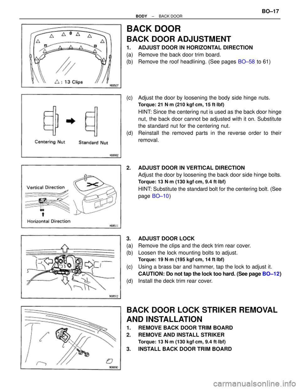
BACK DOOR
BACK DOOR ADJUSTMENT
1. ADJUST DOOR IN HORIZONTAL DIRECTION
(a) Remove the back door trim board.
(b) Remove the roof headlining. (See pages BO±58 to 61)
(c) Adjust the door by loosening the body side hinge nuts.
Torque: 21 NVm (210 kgfVcm, 15 ftVlbf)
HINT: Since the centering nut is used as the back door hinge
nut, the back door cannot be adjusted with it on. Substitute
the standard nut for the centering nut.
(d) Reinstall the removed parts in the reverse order to their
removal.
2. ADJUST DOOR IN VERTICAL DIRECTION
Adjust the door by loosening the back door side hinge bolts.
Torque: 13 NVm (130 kgfVcm, 9.4 ftVlbf)
HINT: Substitute the standard bolt for the centering bolt. (See
page BO±10)
3. ADJUST DOOR LOCK
(a) Remove the clips and the deck trim rear cover.
(b) Loosen the lock mounting bolts to adjust.
Torque: 19 NVm (195 kgfVcm, 14 ftVlbf)
(c) Using a brass bar and hammer, tap the lock to adjust it.
CAUTION: Do not tap the lock too hard. (See page BO±12)
(d) Install the deck trim rear cover.
BACK DOOR LOCK STRIKER REMOVAL
AND INSTALLATION
1. REMOVE BACK DOOR TRIM BOARD
2. REMOVE AND INSTALL STRIKER
Torque: 13 NVm (130 kgfVcm, 9.4 ftVlbf)
3. INSTALL BACK DOOR TRIM BOARD
± BODYBACK DOORBO±17
Page 823 of 2543

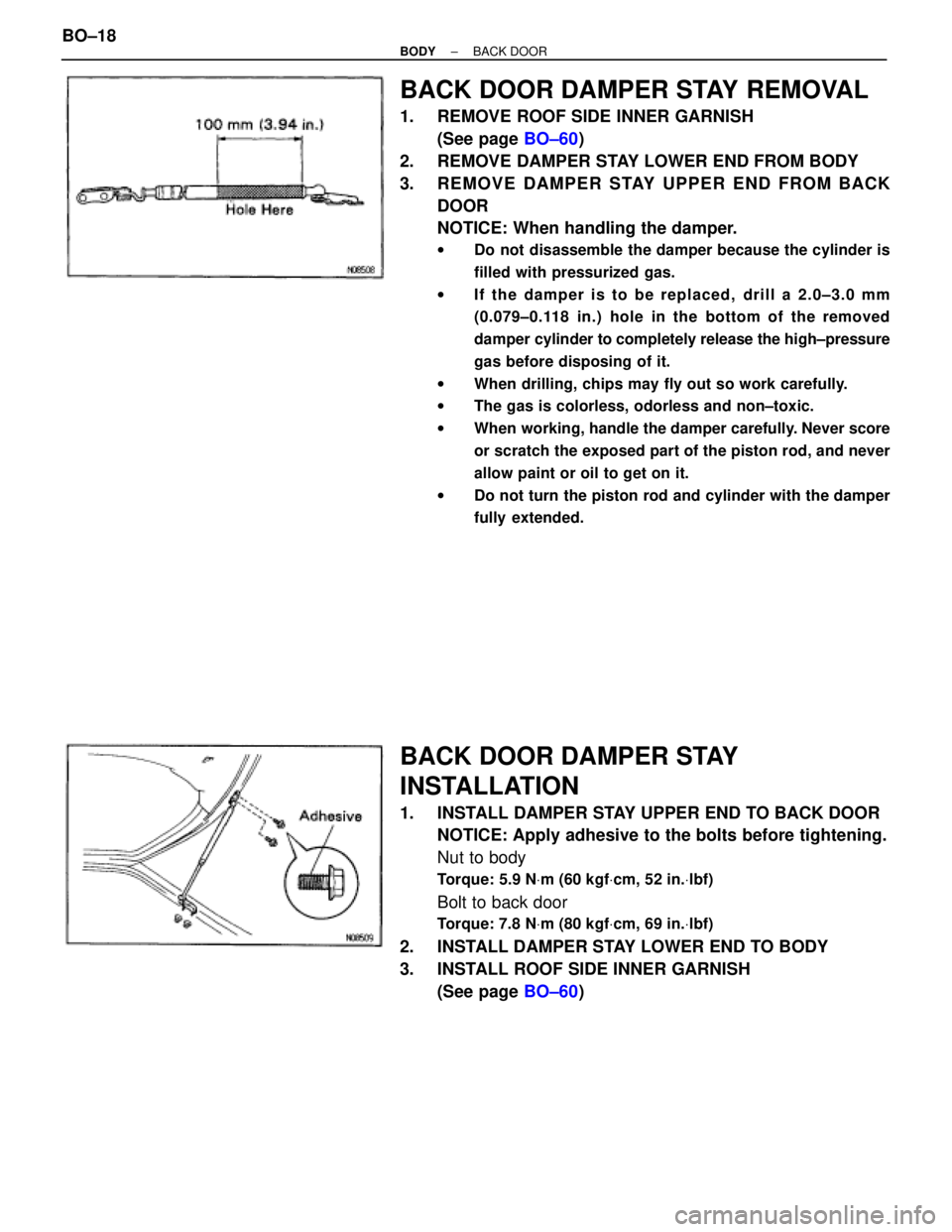
BACK DOOR DAMPER STAY REMOVAL
1. REMOVE ROOF SIDE INNER GARNISH
(See page BO±60)
2. REMOVE DAMPER STAY LOWER END FROM BODY
3. REMOVE DAMPER STAY UPPER END FROM BACK
DOOR
NOTICE: When handling the damper.
wDo not disassemble the damper because the cylinder is
filled with pressurized gas.
wIf the damper is to be replaced, drill a 2.0±3.0 mm
(0.079±0.118 in.) hole in the bottom of the removed
damper cylinder to completely release the high±pressure
gas before disposing of it.
wWhen drilling, chips may fly out so work carefully.
wThe gas is colorless, odorless and non±toxic.
wWhen working, handle the damper carefully. Never score
or scratch the exposed part of the piston rod, and never
allow paint or oil to get on it.
wDo not turn the piston rod and cylinder with the damper
fully extended.
BACK DOOR DAMPER STAY
INSTALLATION
1. INSTALL DAMPER STAY UPPER END TO BACK DOOR
NOTICE: Apply adhesive to the bolts before tightening.
Nut to body
Torque: 5.9 NVm (60 kgfVcm, 52 in.Vlbf)
Bolt to back door
Torque: 7.8 NVm (80 kgfVcm, 69 in.Vlbf)
2. INSTALL DAMPER STAY LOWER END TO BODY
3. INSTALL ROOF SIDE INNER GARNISH
(See page BO±60) BO±18
± BODYBACK DOOR
Page 832 of 2543
ROOF DRIP SIDE FINISH MOULDING
REMOVAL
Normal roof
1. REMOVE ROOF SIDE RAIL WEATHERSTRIP
Using a clip remover, remove 2 clips for front and 3 clips for
rear side of the weatherstrip and remove the weatherstrip.
2. REMOVE ROOF SIDE RAIL WEATHERSTRIP RETAINER
Remove 3 screws and the retainer.
3. REMOVE ROOF DRIP SIDE FINISH MOULDING
Remove 9 screws and the moulding.
Sport roof
1. REMOVE THESE PARTS:
(a) Removable roof
(b) Assist grip (See page BO±60)
(c) Front pillar garnish (See page BO±60)
(d) Interior light
(e) Sunvisor and holder
(f) Front roof headlining (See page BO±61)
(g) Wind deflector panel
2. REMOVE ROOF SIDE RAIL WEATHERSTRIP
(a) Remove 2 bolts from the front weatherstrip.
(b) Using a clip remover, remove 2 clips and the weatherstrip.
3. REMOVE ROOF DRIP SIDE FINISH MOULDING
Remove 4 screws and the moulding.
± BODYBODY OUTSIDE MOULDINGBO±27
Page 833 of 2543
ROOF DRIP SIDE FINISH MOULDING
INSTALLATION
Normal roof
1. INSTALL ROOF DRIP SIDE FINISH MOULDING
Install the moulding with 9 screws.
HINT: Tighten the screws from front to rear.
2. INSTALL ROOF SIDE RAIL WEATHERSTRIP RETAINER
Install the retainer with 3 screws.
3. INSTALL OUTSIDE GARNISH SEAL
Install the garnish seal to the retainer as shown in the illustra-
tion.
4. APPLY SEAL PACKING
Apply seal packing to the moulding and retainer as shown in
the illustration.
T: 3 mm (0.12 in.) or more
Part No. 08826±00080
5. INSTALL ROOF SIDE RAIL WEATHERSTRIP
(a) Install the butyl tape to the weatherstrip as shown in the
illustration.
(b) Install the weatherstrip.
Sport roof
1. INSTALL ROOF DRIP SIDE FINISH MOULDING
Install the moulding with 4 screws.
HINT: Tighten the screws from front to rear.
2. INSTALL OUTSIDE GARNISH SEAL
Install the garnish seal to the moulding as shown in the il-
lustration. BO±28
± BODYBODY OUTSIDE MOULDING