Page 118 of 2543

INTRODUCTIONGLOSSARY OF SAE AND TOYOTA TERMS -
IN-7
GLOSSARY OF SAE AND TOYOTA TERMS
This glossary lists all SAE-J1930 terms and abbreviations used in this manual in compliance with SAE
recommendations, as well as their Toyota equivalents.
SAE
ABBREVIATIONSSAE TERMSTOYOTA TERMS
( )--ABBREVIATIONS
A/CAir ConditioningAir Conditioner
ACLAir CleanerAir Cleaner
AIRSecondary Air InjectionAir Injection (AI)
APAccelerator Pedal-
B+Battery Positive Voltage+B, Battery Voltage
BAROBarometric Pressure-
CACCharge Air CoolerIntercooler
CARBCarburetorCarburetor
CFIContinuous Fuel Injection-
CKPCrankshaft PositionCrank Angle
CLClosed LoopClosed Loop
CMPCamshaft PositionCam Angle
CPPClutch Pedal Position-
CTOXContinuous Trap Oxidizer-
CTPClosed Throttle Position-
DFIDirect Fuel Injection (Diesel)Direct Injection (DI)
DIDistributor Ignition-
DLC1
DLC2
DLC3Data Link Connector 1
Data Link Connector 2
Data Link Connector 31: Check Connector
2: Toyota Diagnosis Communication Link (TDCL)
3: OBD II Diagnostic Connector
DTCDiagnostic Trouble CodeDiagnostic Code
DTMDiagnostic Test Mode-
ECLEngine Control Level-
ECMEngine Control ModuleEngine ECU (Electronic Control Unit)
ECTEngine Coolant TemperatureCoolant Temperature, Water Temperature (THW)
EEPROMElectrically Erasable Programmable Read Only
MemoryElectrically Erasable Programmable Read Only Memory
(EEPROM),
Erasable Programmable Read Only Memory(EPROM)
EFEEarly Fuel EvaporationCold Mixture Heater (CMH), Heat Control Valve (HCV)
EGRExhaust Gas RecirculationExhaust Gas Recirculation (EGR)
EIElectronic IgnitionToyota Distributorless Ignition (TDI)
EMEngine ModificationEngine Modification (EM)
EPROMErasable Programmable Read Only MemoryProgrammable Read Only Memory (PROM)
EVAPEvaporative EmissionEvaporative Emission Control (EVAP)
FCFan Control-
FEEPROMFlash Electrically Erasable Programmable
Read Only Memory-
FEPROMFlash Erasable Programmable Read Only Memory-
FFFlexible Fuel-
FPFuel PumpFuel Pump
GENGeneratorAlternator
GNDGroundGround (GND)
HO2SHeated Oxygen SensorHeated Oxygen Sensor (HO2S)
IN016-02
Page 415 of 2543

ELECTRONIC CONTROL COMPONENTS
INSPECTION
1. INSPECT SHIFT LOCK CONTROL ECU
Using a voltmeter, measure the voltage at each terminal.
����� �����Connector������ ������Terminal������������������� �������������������Measuring condition��������� ���������Voltage (V)
����� ����������� ������ACC ± E������������������� �������������������IG SW ACC��������� ���������10 ± 14
����� ����������� ������IG ± E������������������� �������������������IG SW ON��������� ���������10 ± 14
����� �����
A
������ ������STP ± E������������������� �������������������Depress brake pedal��������� ���������10 ± 14
����� �����A������ ���������� ����(1)���������������� ����������������IG SW ACC and P position��������� ���������Below 1
����� ����������� ������KLS ± E���� ����(2)���������������� ����������������R, N, D, 2, L position��������� ���������7.5 ± 11����� ����������� ���������� ����(3)���������������� ����������������R, N, D, 2, L position (after 1 second)��������� ���������6 ± 9.5����� ����������� ���������� ����(1)���������������� ����������������IG SW ON and P position��������� ���������Below 1����� �����
B
������ ������
SLS ( ) SLS (+)
���� ����(2)���������������� ����������������Depress brake pedal��������� ���������8 ± 13.5����� �
���� �����
B������ �
����� ������
SLS (±) ± SLS (+)���� �
��� ����(3)���������������� �
��������������� ����������������Depress brake pedal (after 20 seconds)��������� �
�������� ���������6 ± 8.5
����� ����������� ���������� ����(4)���������������� ����������������R, N, D, 2, L position��������� ���������Below 1
����� ����������� ������P1P���� ����(1)���������������� ����������������IG SW ON, P position and depress brake pedal��������� ���������Below 1
����� �����C������ ������
P1 ± P
���� ����(2)���������������� ����������������R, N, D, 2, L position��������� ���������9 ± 13.5
����� �����C������ ������P2P���� ����(1)���������������� ����������������IG SW ACC and P position��������� ���������9 ± 13.5
����� ����������� ������P2 ± P���� ����(2)���������������� ����������������R, N, D, 2, L position��������� ���������Below 1
2. INSPECT SHIFT LOCK SOLENOID
(a) Disconnect the solenoid connector.
(b) Usin g an oh mme te r, me a su re th e re sista n ce be twe e n
terminals 1 and 2.
Standard resistance:
20±28 �
If resistance value is not as specified, replace the solenoid.
(c) Apply battery positive voltage between terminals 1 and 2. At
this time, confirm that the solenoid operates.
If the solenoid does not operated, replace the solenoid.
± AT340E (2JZ±GE) AUTOMATIC TRANSMISSIONSHIFT LOCK SYSTEMAT1±29
Page 416 of 2543
 Disconnect the solenoid connector.
(b) Usin g an oh mme te r, me a su re th e re sista n ce be twe e n
terminals 1 and 2.
Standard resistance:
12±17 �
If resi")
3. INSPECT KEY INTERLOCK SOLENOID
(a) Disconnect the solenoid connector.
(b) Usin g an oh mme te r, me a su re th e re sista n ce be twe e n
terminals 1 and 2.
Standard resistance:
12±17 �
If resistance value is not as specified, replace the solenoid.
(c) Touch the solenoid with your finger and check that solenoid
operation can be felt when battery positive voltage is applied
intermittently to the terminals 1 and 2.
If the solenoid does not operated, replace the solenoid.
4. INSPECT SHIFT LOCK CONTROL SWITCH
Inspect that there is continuity between each terminal.
��������� �
�������� ���������Shift position
������� �
������ �������Tester condition to
terminal number�������� �
������� ��������Specified value
��������� ���������P position (ReleasePPContinuity��������� ���������P osition (Release
button is not pushed)P±P1Continuity
��������� ���������RND2LpositionPPContinuity���������R, N, D, 2, L positionP±P2Continuity
AT1±30± AT340E (2JZ±GE) AUTOMATIC TRANSMISSIONSHIFT LOCK SYSTEM
Page 451 of 2543
INSPECTION PROCEDURE
Check sensor resistance
Remove A/T fluid temp. sensor.
Measure resistance between terminals of A/T fluid
temp. sensor at 20°C (68°F) and 110°C (230°F).
Resistance:
20°C (68°F) Approx. 12.08 k�
110°C (230°F) Approx. 0.78 k�
Replace A/T fluid temp. sensor.
Repair or replace harness or connector.
Check harness and connector between battery and A/T fluid temp. sensor
A/T fluid temp. sensor and ECM. (See page IN±30).
Check A/T fluid temp. sensor.
Check and replace ECM. AT1±65
± AT340E (2JZ±GE) AUTOMATIC TRANSMISSIONTROUBLESHOOTING
Page 460 of 2543
 lead to termina")
Jack up the vehicle.
Remove the oil pan.
Disconnect the solenoid connector.
Measure resistance between solenoid connector
and solenoid body.
Resistance: 10 ± 16 �
Connect positive (+) lead to terminal of solenoid
connector, negative (±) lead to solenoid body.
Check No. 1, No. 2 solenoid valves.
When battery positive voltage is supplied to
the solenoid valves, check that the solenoid
valves open.
Replace solenoid valve.
Electrical Check
Repair or replace harness or connector.
Check harness and connector between ECM and solenoid (See page IN±30).
Proceed to next circuit inspection shown on matrix chart
(See page AT1±58). However, when diagnostic trouble
code 62 or 63 is displayed, check and replace ECM.
Applying 490 kPa (5 kgf/cm2, 71 psi) of com-
pressed air, check that the solenoid valves do
not leak air.
Remove the oil pan.
Remove the No. 1 and No. 2 solenoid valves.
The solenoid makes an operating noise.
Mechanical Check
INSPECTION PROCEDURE
AT1±74± AT340E (2JZ±GE) AUTOMATIC TRANSMISSIONTROUBLESHOOTING
Page 462 of 2543

Jack up the vehicle.
Remove the oil pan.
Disconnect the lock±up solenoid valve connector.
Measure resistance between lock-up solenoid
connector and solenoid body.
Resistance: 10 ± 16 �
Connect lock±up solenoid valve operation noise
when battery positive voltage is applied to the so-
lenoid connector terminal and solenoid body.
Check lock±up solenoid valve.
When battery positive voltage is supplied to
the solenoid valve, check that the solenoid
valve opens.
Replace lock±up solenoid valve.
Electrical Check
Repair or replace harness or connector.
Check harness and connector between lock±up solenoid valve and ECM
(See page IN±30).
Proceed to next circuit inspection shown on matrix chart
(See page AT1±58). However, when diagnostic trouble
code 64 is displayed, check and replace ECM.
Applying 490 kPa (5 kgf/cm2, 71 psi) of com-
pressed air, check that the solenoid valve
does not leak air.
Remove lock±up solenoid valve from valve body.
The lock±up solenoid valve makes operation
noise.
Mechanical Check
AT1±76± AT340E (2JZ±GE) AUTOMATIC TRANSMISSIONTROUBLESHOOTING
Page 468 of 2543
Connect the Check Harness A to the ECM
(See page EG±404).
Turn ignition switch ON.
Check voltage between terminals NSW, 2, L of ECM connector and body
ground.
Measure voltage between terminals NSW, 2, L of
ECM connector and body ground when the shift
lever is positioned to the following positions.
Proceed to next circuit inspection shown on
matrix chart (See page AT1±58).
Check park/neutral position switch.
Jack up the vehicle.
Remove park/neutral position switch (See
page AT1±15).
Replace park/neutral position switch.
Check harness and connector between battery and park/neutral position
switch, park/neutral position switch and ECM (See page IN±30).
Repair or replace harness and connector.
Check and replace ECM.
Check continuity between each terminal shown
below when the shift lever is positioned to each
position.
The voltage will drop slighty due to lighting up of the
back up light.
INSPECTION PROCEDURE
AT1±82± AT340E (2JZ±GE) AUTOMATIC TRANSMISSIONTROUBLESHOOTING
Page 473 of 2543
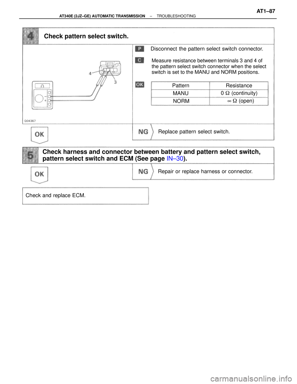
Pattern
Disconnect the pattern select switch connector.
Check pattern select switch.
Repair or replace harness or connector.
Resistance
MANU0 � (continuity)
NORM
Check and replace ECM.
Measure resistance between terminals 3 and 4 of
the pattern select switch connector when the select
switch is set to the MANU and NORM positions.
8� (open)
Replace pattern select switch.
Check harness and connector between battery and pattern select switch,
pattern select switch and ECM (See page IN±30).
± AT340E (2JZ±GE) AUTOMATIC TRANSMISSIONTROUBLESHOOTINGAT1±87
 and 110°C (230°F).
Resistance:
20°C")
.
Turn ignition switch ON.
Check voltage between terminals NSW, 2, L of ECM connector and body
ground.
Measure voltage between terminals NSW,")