Page 1124 of 2543
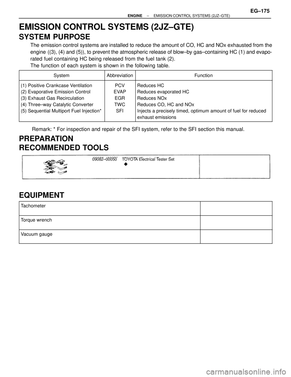
EMISSION CONTROL SYSTEMS (2JZ±GTE)
SYSTEM PURPOSE
The emission control systems are installed to reduce the amount of CO, HC and NOx exhausted from the
engine ((3), (4) and (5)), to prevent the atmospheric release of blow±by gas±containing HC (1) and evapo-
rated fuel containing HC being released from the fuel tank (2).
The function of each system is shown in the following table.
������������� �������������System����� �����Abbreviation�������������������� ��������������������Function������������� �
������������ �
������������ �
������������ �
������������ �
������������ �������������
(1) Positive Crankcase Ventilation
(2) Evaporative Emission Control
(3) Exhaust Gas Recirculation
(4) Three±way Catalytic Converter
(5) Sequential Multiport Fuel Injection*
����� �
���� �
���� �
���� �
���� �
���� �����
PCV
EVAP
EGR
TWC
SFI
�������������������� �
������������������� �
������������������� �
������������������� �
������������������� �
������������������� ��������������������
Reduces HC
Reduces evaporated HC
Reduces NOx
Reduces CO, HC and NOx
Injects a precisely timed, optimum amount of fuel for reduced
exhaust emissions
Remark: * For inspection and repair of the SFI system, refer to the SFI section this manual.
PREPARATION
RECOMMENDED TOOLS
09082±00050 TOYOTA Electrical Tester Set
EQUIPMENT
�������������������������� �
������������������������� ��������������������������Tachometer����������� �
���������� �����������
�������������������������� �
������������������������� ��������������������������
Torque wrench����������� �
���������� �����������
�������������������������� �
������������������������� ��������������������������
Vacuum gauge����������� �
���������� �����������
± ENGINEEMISSION CONTROL SYSTEMS (2JZ±GTE)EG±175
Page 1131 of 2543
4. INSPECT EGR VALVE
Check for sticking and heavy carbon deposits.
If a problem is found, replace the EGR valve.
5. REINSTALL EGR VALVE
(a) Place a new gasket on the air intake chamber.
(b) Install the EGR valve with the 2 nuts.
Torque: 21 NVm (210 kgfVcm, 15 ftVlbf)
(c) Reconnect the following hoses to the EGR valve:
wVacuum hose
wPressure hose
6. REINSTALL EGR GAS TEMPERATURE SENSOR
Torque: 20 NVm (200 kgfVcm, 14 ftVlbf)
7. REINSTALL EGR PIPE
(a) Temporarily install the union nut of the EGR pipe.
(b) Install a new gasket and the EGR pipe with the 2 bolts.
Torque: 27 NVm (280 kgfVcm, 20 ftVlbf)
(c) Tighten the union nut of the EGR pipe.
Torque: 64 NVm (650 kgfVcm, 47 ftVlbf)
EG±182± ENGINEEMISSION CONTROL SYSTEMS (2JZ±GTE)
Page 1135 of 2543
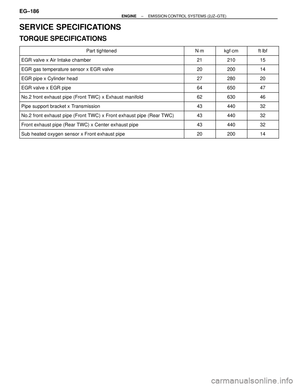
SERVICE SPECIFICATIONS
TORQUE SPECIFICATIONS
����������������������� �����������������������Part tightened����� �����NVm������ ������kgfVcm����� �����ftVlbf
����������������������� �����������������������EGR valve x Air Intake chamber����� �����21������ ������210����� �����15
����������������������� �����������������������EGR gas temperature sensor x EGR valve����� �����20������ ������200����� �����14����������������������� �
���������������������� �����������������������EGR pipe x Cylinder head
����� �
���� �����27
������ �
����� ������280
����� �
���� �����20
����������������������� �����������������������EGR valve x EGR pipe����� �����64������ ������650����� �����47
����������������������� �����������������������No.2 front exhaust pipe (Front TWC) x Exhaust manifold����� �����62������ ������630����� �����46
����������������������� �����������������������Pipe support bracket x Transmission����� �����43������ ������440����� �����32����������������������� �
���������������������� �����������������������No.2 front exhaust pipe (Front TWC) x Front exhaust pipe (Rear TWC)����� �
���� �����43������ �
����� ������440����� �
���� �����32
����������������������� �����������������������Front exhaust pipe (Rear TWC) x Center exhaust pipe����� �����43������ ������440����� �����32
����������������������� �����������������������Sub heated oxygen sensor x Front exhaust pipe����� �����20������ ������200����� �����14
EG±186± ENGINEEMISSION CONTROL SYSTEMS (2JZ±GTE)
Page 1141 of 2543
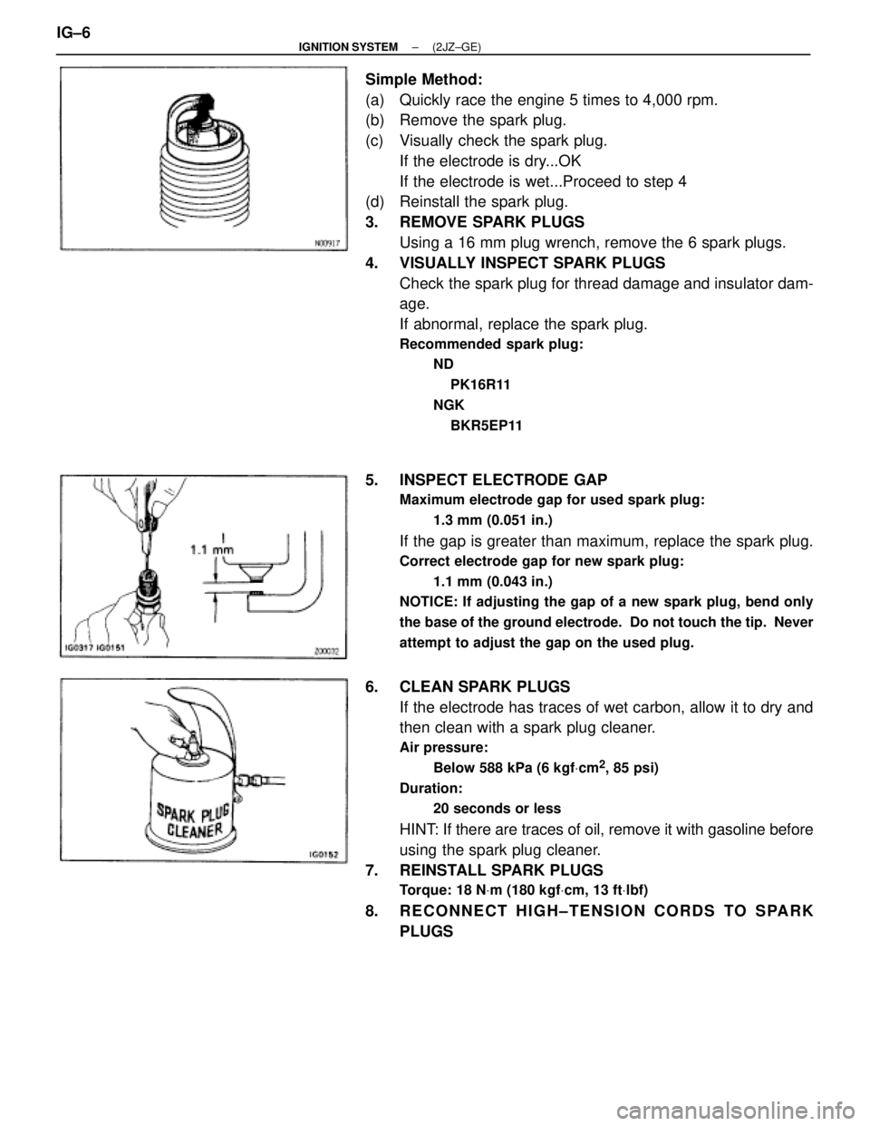
Simple Method:
(a) Quickly race the engine 5 times to 4,000 rpm.
(b) Remove the spark plug.
(c) Visually check the spark plug.
If the electrode is dry...OK
If the electrode is wet...Proceed to step 4
(d) Reinstall the spark plug.
3. REMOVE SPARK PLUGS
Using a 16 mm plug wrench, remove the 6 spark plugs.
4. VISUALLY INSPECT SPARK PLUGS
Check the spark plug for thread damage and insulator dam-
age.
If abnormal, replace the spark plug.
Recommended spark plug:
ND
PK16R11
NGK
BKR5EP11
5. INSPECT ELECTRODE GAP
Maximum electrode gap for used spark plug:
1.3 mm (0.051 in.)
If the gap is greater than maximum, replace the spark plug.
Correct electrode gap for new spark plug:
1.1 mm (0.043 in.)
NOTICE: If adjusting the gap of a new spark plug, bend only
the base of the ground electrode. Do not touch the tip. Never
attempt to adjust the gap on the used plug.
6. CLEAN SPARK PLUGS
If the electrode has traces of wet carbon, allow it to dry and
then clean with a spark plug cleaner.
Air pressure:
Below 588 kPa (6 kgfVcm
2, 85 psi)
Duration:
20 seconds or less
HINT: If there are traces of oil, remove it with gasoline before
using the spark plug cleaner.
7. REINSTALL SPARK PLUGS
Torque: 18 NVm (180 kgfVcm, 13 ftVlbf)
8. RECONNECT HIGH±TENSION CORDS TO SPARK
PLUGS IG±6
± IGNITION SYSTEM(2JZ±GE)
Page 1153 of 2543
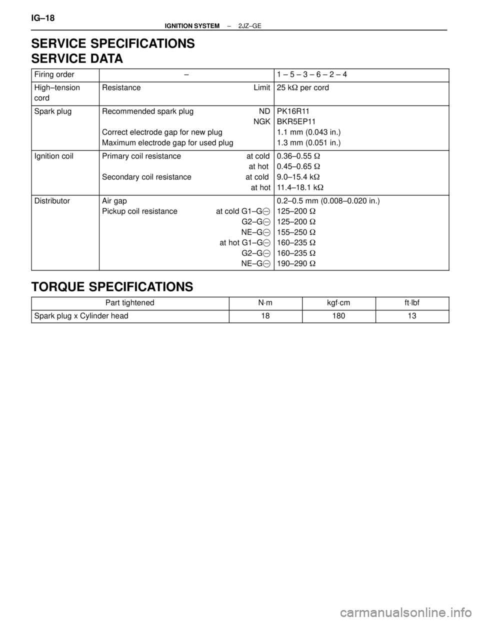
SERVICE SPECIFICATIONS
SERVICE DATA
������� �������Firing order��������������� ���������������±���������������� ����������������1 ± 5 ± 3 ± 6 ± 2 ± 4������� �
������ �������High±tension
cord��������������� �
�������������� ���������������Resistance Limit���������������� �
��������������� ����������������25 k� per cord
������� �
������ �
������ �
������ �������
Spark plug��������������� �
�������������� �
�������������� �
�������������� ���������������
Recommended spark plug ND
NGK
Correct electrode gap for new plug
Maximum electrode gap for used plug���������������� �
��������������� �
��������������� �
��������������� ����������������
PK16R11
BKR5EP11
1.1 mm (0.043 in.)
1.3 mm (0.051 in.)
������� �
������ �
������ �
������ �������
Ignition coil��������������� �
�������������� �
�������������� �
�������������� ���������������
Primary coil resistance at cold
at hot
Secondary coil resistance at cold
at hot���������������� �
��������������� �
��������������� �
��������������� ����������������
0.36±0.55 �
0.45±0.65 �
9.0±15.4 k�
11.4±18.1 k�
������� �
������ �
������ �
������ �
������ �
������ �������
Distributor��������������� �
�������������� �
�������������� �
�������������� �
�������������� �
�������������� ���������������
Air gap
Pickup coil resistance at cold G1±G�
G2±G�
NE±G�
at hot G1±G�
G2±G�
NE±G����������������� �
��������������� �
��������������� �
��������������� �
��������������� �
��������������� ����������������
0.2±0.5 mm (0.008±0.020 in.)
125±200 �
125±200 �
155±250 �
160±235 �
160±235 �
190±290 �
TORQUE SPECIFICATIONS
����������������� �����������������Part tightened������� �������NVm������� �������kgfVcm������� �������ftVlbf
����������������� �����������������Spark plug x Cylinder head������� �������18������� �������180������� �������13
IG±18± IGNITION SYSTEM2JZ±GE
Page 1158 of 2543
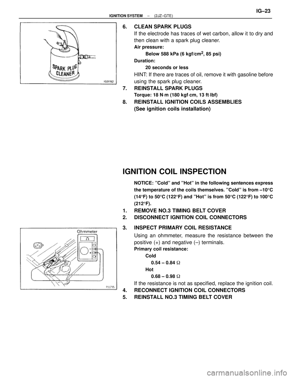
6. CLEAN SPARK PLUGS
If the electrode has traces of wet carbon, allow it to dry and
then clean with a spark plug cleaner.
Air pressure:
Below 588 kPa (6 kgf/cm
2, 85 psi)
Duration:
20 seconds or less
HINT: If there are traces of oil, remove it with gasoline before
using the spark plug cleaner.
7. REINSTALL SPARK PLUGS
Torque: 18 NVm (180 kgfVcm, 13 ftVlbf)
8. REINSTALL IGNITION COILS ASSEMBLIES
(See ignition coils installation)
IGNITION COIL INSPECTION
NOTICE: ºColdº and ºHotº in the following sentences express
the temperature of the coils themselves. ºColdº is from ±105C
(145F) to 505C (1225F) and ºHotº is from 505C (1225F) to 1005C
(2125F).
1. REMOVE NO.3 TIMING BELT COVER
2. DISCONNECT IGNITION COIL CONNECTORS
3. INSPECT PRIMARY COIL RESISTANCE
Using an ohmmeter, measure the resistance between the
positive (+) and negative (±) terminals.
Primary coil resistance:
Cold
0.54 ± 0.84 �
Hot
0.68 ± 0.98 �
If the resistance is not as specified, replace the ignition coil.
4. RECONNECT IGNITION COIL CONNECTORS
5. REINSTALL NO.3 TIMING BELT COVER
± IGNITION SYSTEM(2JZ±GTE)IG±23
Page 1162 of 2543
4. REMOVE BRACKET IGNITION COILS ASSEMBLIES
Remove the 2 bolts and 2 ignition coils assembly.
Torque:
Bracket to cylinder head cover
8.8 NVm (90 kgfVcm, 78 in.Vlbf)
5. REMOVE IGNITION COILS FROM BRACKET
(a) Remove the rubber boot from the ignition coil.
(b) Remove the 2 screws and ignition coil.
± IGNITION SYSTEM(2JZ±GTE)IG±27
Page 1163 of 2543
CAMSHAFT POSITION SENSOR
COMPONENTS FOR REMOVAL AND
INSTALLATION
CAMSHAFT POSITION SENSOR
REMOVAL
Installation is in the reverse order of removal.
1. DISCONNECT IAC VALVE CONNECTOR
2. DISCONNECT AIR HOSE FROM IAC VALVE
3. REMOVE ENGINE HANGER
Remove the 2 bolts, ground strap and engine hanger.
Torque: 39 NVm (400 kgfVcm, 29 ftVlbf)
4. DISCONNECT CAMSHAFT POSITION SENSOR
CONNECTORS
5. REMOVE CAMSHAFT POSITION SENSORS
Remove the 4 bolts, 2 camshaft position sensors and 2 gas-
kets.
Torque: 6.4 NVm (65 kgfVcm, 56 in.Vlbf)
IG±28± IGNITION SYSTEM2JZ±GTE