Page 1057 of 2543

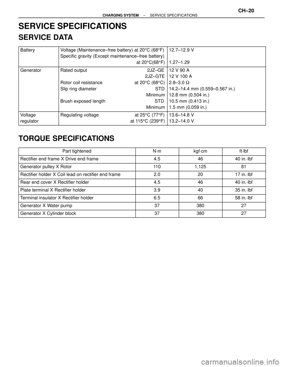
SERVICE SPECIFICATIONS
SERVICE DATA
������� �
������ �
������ �������
Battery���������������� �
��������������� �
��������������� ����������������
Voltage (Maintenance±free battery) at 205C (685F)
Specific gravity (Except maintenance±free battery)
at 205C(685F)��������������� �
�������������� �
�������������� ���������������
12.7±12.9 V
1.27±1.29
������� �
������ �
������ �
������ �
������ �
������ �������
Generator���������������� �
��������������� �
��������������� �
��������������� �
��������������� �
��������������� ����������������
Rated output 2JZ±GE
2JZ±GTE
Rotor coil resistance at 205C (685C)
Slip ring diameter STD
Minimum
Brush exposed length STD
Minimum��������������� �
�������������� �
�������������� �
�������������� �
�������������� �
�������������� ���������������
12 V 90 A
12 V 100 A
2.8±3.0 �
14.2±14.4 mm (0.559±0.567 in.)
12.8 mm (0.504 in.)
10.5 mm (0.413 in.)
1.5 mm (0.059 in.)
������� �
������ �������Voltage
regulator���������������� �
��������������� ����������������Regulating voltage at 255C (775F)
at 1155C (2395F)��������������� �
�������������� ���������������13.6±14.8 V
13.2±14.0 V
TORQUE SPECIFICATIONS
����������������� �����������������Part tightened������� �������NVm������� �������kgfVcm������� �������ftVlbf����������������� �����������������Rectifier end frame X Drive end frame������� �������4.5������� �������46������� �������40 in.Vlbf����������������� �
����������������
�����������������
Generator pulley X Rotor�������
������� �������11 0������� �
������ �������1,125������� �
������ �������81
����������������� �����������������Rectifier holder X Coil lead on rectifier end frame������� �������2.0������� �������20������� �������17 in.Vlbf
����������������� �����������������Rear end cover X Rectifier holder������� �������4.5������� �������46������� �������40 in.Vlbf
����������������� �����������������Plate terminal X Rectifier holder������� �������3.9������� �������40������� �������35 in.Vlbf
����������������� �����������������Terminal insulator X Rectifier holder������� �������6.5������� �������66������� �������58 in.Vlbf
����������������� �����������������Generator X Water pump������� �������37������� �������380������� �������27
����������������� �����������������Generator X Cylinder block������� �������37������� �������380������� �������27
± CHARGING SYSTEMSERVICE SPECIFICATIONSCH±20
Page 1059 of 2543
PREPARATION
SST (SPECIAL SERVICE TOOLS)
09023±00100 Union Nut Wrench 10 mm
09301±00110 Clutch Guide Tool
Clutch line
09303±35011 Input Shaft Front Bearing Puller
09304±30012 Input Shaft Front Bearing
Replacer
09333±00013 Clutch Diaphragm Spring Aligner
2JZ±GE Only
RECOMMENDED TOOLS
09082±00050 TOYOTA Electrical Tester Set
09905±00012Snap Ring No. 1 Expander
EQUIPMENT
������������������������� �
������������������������ ������������������������� Calipers
����������� �
���������� �����������
������������������������� ������������������������� Dial indicator������������������������� ������������������������� Dial indicator
������������������������� ������������������������� To rque wrench������������������������� ������������������������� Torque wrench
CL±2± CLUTCHPREPARATION
Page 1063 of 2543
CLUTCH MASTER CYLINDER
COMPONENTS
MASTER CYLINDER REMOVAL
Installation is in the reverse order of removal.
1. DRAIN OUT FLUID WITH SYRINGE
INSTALLATION HINT: After installation, adjust the clutch
pedal and bleed the clutch system.
2. DISCONNECT CLUTCH LINE UNION
Using SST, disconnect the union nut.
SST 09023±00100
Torque: 15 NVm (155 kgfVcm, 11 ftVlbf)
3. REMOVE CLIP AND PIN
4. REMOVE 2 MOUNTING NUTS AND PULL OUT MASTER
CYLINDER
Torque: 12 NVm (125 kgfVcm, 9 ftVlbf)
CL±6± CLUTCHCLUTCH MASTER CYLINDER
Page 1065 of 2543
CLUTCH RELEASE CYLINDER
(2JZ±GTE)
COMPONENTS
RELEASE CYLINDER REMOVAL
Installation is in the reverse order of removal.
INSTALLATION HINT: After installation, adjust the clutch
pedal and bleed the clutch system.
1. REMOVE CLUTCH HOUSING COVER LH
Remove the 2 bolts.
Torque: 12 NVm (120 kgfVcm, 9 ftVlbf)
2. DISCONNECT CLUTCH LINE
Using SST, disconnect the clutch line union. Use a container
to catch the fluid.
SST 09023±00100
Torque: 15 NVm (155 kgfVcm, 11 ftVlbf)
3. REMOVE 2 BOLTS AND PULL OUT RELEASE CYLINDER
Torque: 12 NVm (120 kgfVcm, 9 ftVlbf)
CL±8± CLUTCHCLUTCH RELEASE CYLINDER (2JZ±GTE)
Page 1067 of 2543
RELEASE CYLINDER REMOVAL
Installation is in the reverse order of removal.
INSTALLATION HINT: After installation, adjust the clutch
pedal and bleed the clutch system.
1. DISCONNECT CLUTCH LINE
Using SST, disconnect the clutch line union. Use a container
to catch the fluid.
SST 09023±00100
Torque: 15 NVm (155 kgfVcm, 11 ftVlbf)
2. REMOVE RELEASE CYLINDER WITH 3 BOLTS
Torque:
A: 12 NVm (120 kgfVcm, 9 ftVlbf)
B: 4.9 NVm (50 kgfVcm, 43 in.Vlbf)
RELEASE CYLINDER DISASSEMBLY
1. PULL OUT PUSH ROD WITH BOOT
2. REMOVE PISTON WITH SPRING
Using compressed air, remove the piston and spring from the
cylinder.
RELEASE CYLINDER ASSEMBLY
1. COAT PISTON WITH LITHIUM SOAP BASE GLYCOL
GREASE, AS SHOWN
2. INSTALL PISTON WITH SPRING INTO CYLINDER
3. INSTALL BOOT WITH PUSH ROD TO CYLINDER CL±10
± CLUTCHCLUTCH RELEASE CYLINDER (2JZ±GE)
Page 1070 of 2543
4. INSPECT PILOT BEARING
Turn the bearing by hand while applying force in the axial
direction.
If the bearing sticks or has much resistance, replace the pilot
bearing.
5. IF NECESSARY, REPLACE PILOT BEARING
(a) Remove the 2 bolts at diametrically opposite points.
(b) Using SST, remove the pilot bearing.
SST 09303±35011
(c) Using SST and a hammer, drive in a new pilot bearing.
SST 09301±00110
(d) Install 2 new bolts.
(e) First, torque the 2 bolts uniformly a little at a time.
Torque: 49 NVm (500 kgfVcm, 36 ftVlbf)
(f) Then tighten the 2 bolts an additional 80±100°.
± CLUTCHCLUTCH UNIT (2JZ±GTE)CL±13
Page 1072 of 2543

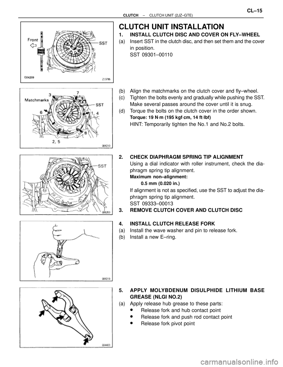
CLUTCH UNIT INSTALLATION
1. INSTALL CLUTCH DISC AND COVER ON FLY±WHEEL
(a) Insert SST in the clutch disc, and then set them and the cover
in position.
SST 09301±00110
(b) Align the matchmarks on the clutch cover and fly±wheel.
(c) Tighten the bolts evenly and gradually while pushing the SST.
Make several passes around the cover until it is snug.
(d) Torque the bolts on the clutch cover in the order shown.
Torque: 19 NVm (195 kgfVcm, 14 ftVlbf)
HINT: Temporarily tighten the No.1 and No.2 bolts.
2. CHECK DIAPHRAGM SPRING TIP ALIGNMENT
Using a dial indicator with roller instrument, check the dia-
phragm spring tip alignment.
Maximum non±alignment:
0.5 mm (0.020 in.)
If alignment is not as specified, use the SST to adjust the dia-
phragm spring tip alignment.
SST 09333±00013
3. REMOVE CLUTCH COVER AND CLUTCH DISC
4. INSTALL CLUTCH RELEASE FORK
(a) Install the wave washer and pin to release fork.
(b) Install a new E±ring.
5. APPLY MOLYBDENUM DISULPHIDE LITHIUM BASE
GREASE (NLGI NO.2)
(a) Apply release hub grease to these parts:
wRelease fork and hub contact point
wRelease fork and push rod contact point
wRelease fork pivot point
± CLUTCHCLUTCH UNIT (2JZ±GTE)CL±15
Page 1076 of 2543
4. INSPECT PILOT BEARING
Turn the bearing by hand while applying force in the axial
direction.
If the bearing sticks or has much resistance, replace the pilot
bearing.
5. IF NECESSARY, REPLACE PILOT BEARING
(a) Remove the 2 bolts at diametrically opposite points.
(b) Using SST, remove the pilot bearing.
SST 09303±35011
(c) Using SST and a hammer, drive in a new pilot bearing.
SST 09304±30012
(d) Install 2 new bolts.
(e) First, torque the 2 bolts uniformly a little at a time.
Torque: 49 NVm (500 kgfVcm, 36 ftVlbf)
(f) Then tighten the 2 bolts an additional 80±100°.
± CLUTCHCLUTCH UNIT (2JZ±GE)CL±19