Page 878 of 2543
TRAC CONTROL SYSTEM BLEEDING
HINT: When repairing the brake master cylinder or TRAC sys-
tem, bleed the air out of the TRAC system.
1. INSPECT BATTERY POSITIVE VOLTAGE
Battery positive voltage:
10±14 V
2. BLEED TRACTION CONTROL SYSTEM
(a) Disconnect the connector from the TRAC pump.
(b) Connect SST to the TRAC pump.
SST 09990±00330
(c) Connect a vinyl tube to the bleeder plug of the TRAC
actuator, then loosen the bleeder plug.
(d) Start the engine.
(e) Connect the SST to the battery. Then wait at least 60
seconds before tightening the bleeder plug with the TRAC
pump still operating.
Torque: 8.3 NVm (85 kgfVcm, 74 in.Vlbf)
(f) After tightening the bleeder plug, keep the TRAC pump
operating for approximately 30 seconds.
(g) Install the cap.
3. CHECK FLUID LEVEL IN RESERVOIR
Fluid:
SAE J1703 or FMVSS NO. 116 DOT3
4. CLEAR DIAGNOSTIC TROUBLE CODES
(See page BR±127)
± BRAKE SYSTEMCHECK AND ADJUSTMENTBR±9
Page 879 of 2543
PARKING BRAKE CHECK AND
ADJUSTMENT
1. CHECK PARKING BRAKE LEVER TRAVEL
Pull the parking brake lever all the way up, and count the
number of clicks.
Parking brake lever travel at 196 N (20 kgf, 44.1 lbf):
5±8 clicks
If incorrect, adjust the parking brake.
2. IF NECESSARY, ADJUST PARKING BRAKE
HINT: Before adjusting the parking brake, make sure that the
rear brake shoe clearance has been adjusted.
For shoe clearance adjustment, see page BR±39.
(a) Remove the upper console panel.
(b) Remove the screw and parking brake hole cover.
(c) Using a socket driver and spanner wrench, remove the
adjusting lock nut.
(d) Turn the adjusting nut until the lever travel is correct.
(e) Install the adjusting lock nut.
(f) Using a socket driver and spanner wrench, tighten the
adjusting lock nut.
Torque: 5.4 NVm (55 kgfVcm, 48 in.Vlbf)
(g) Install the parking brake hole cover with the screw.
(h) Install the upper console panel. BR±10
± BRAKE SYSTEMCHECK AND ADJUSTMENT
Page 882 of 2543
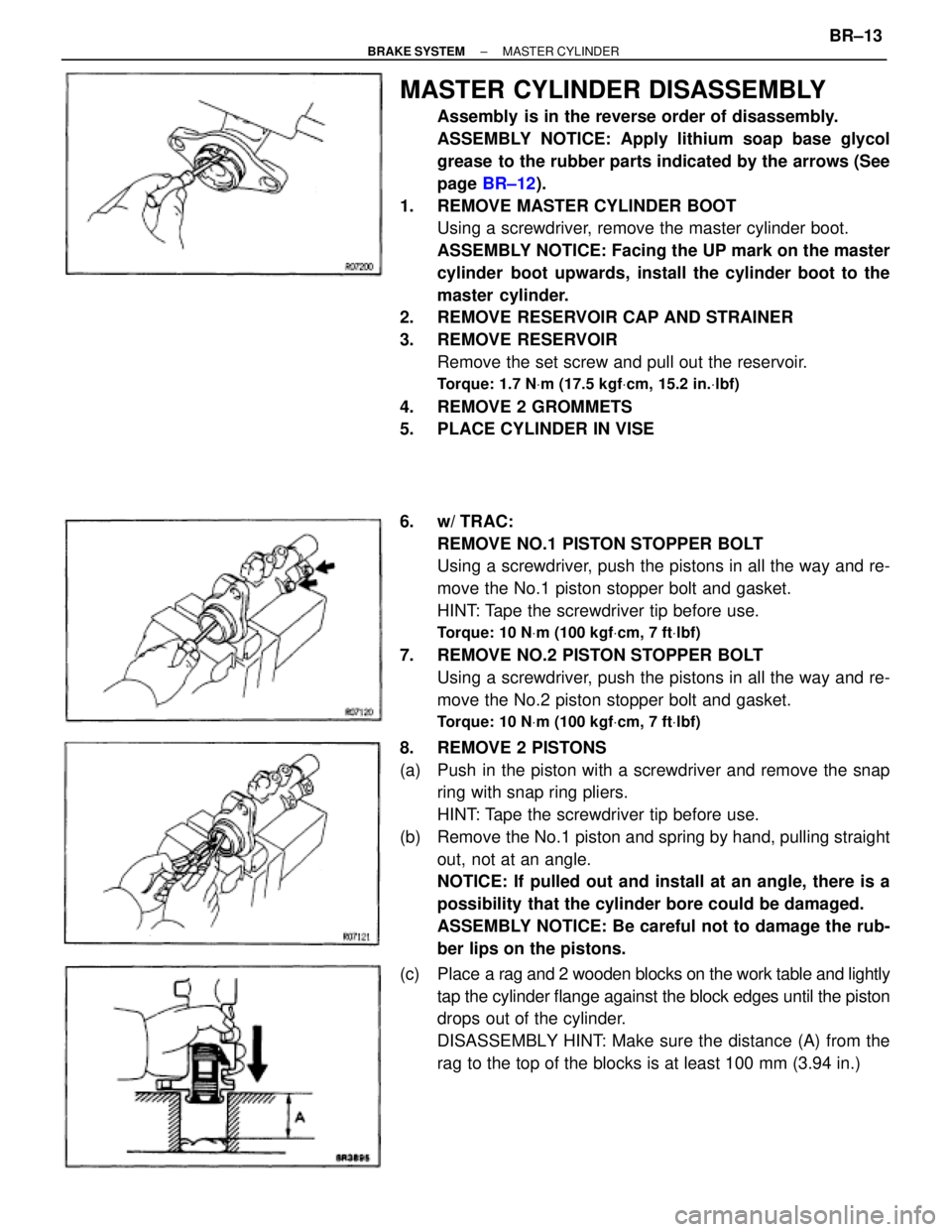
MASTER CYLINDER DISASSEMBLY
Assembly is in the reverse order of disassembly.
ASSEMBLY NOTICE: Apply lithium soap base glycol
grease to the rubber parts indicated by the arrows (See
page BR±12).
1. REMOVE MASTER CYLINDER BOOT
Using a screwdriver, remove the master cylinder boot.
ASSEMBLY NOTICE: Facing the UP mark on the master
cylinder boot upwards, install the cylinder boot to the
master cylinder.
2. REMOVE RESERVOIR CAP AND STRAINER
3. REMOVE RESERVOIR
Remove the set screw and pull out the reservoir.
Torque: 1.7 NVm (17.5 kgfVcm, 15.2 in.Vlbf)
4. REMOVE 2 GROMMETS
5. PLACE CYLINDER IN VISE
6. w/ TRAC:
REMOVE NO.1 PISTON STOPPER BOLT
Using a screwdriver, push the pistons in all the way and re-
move the No.1 piston stopper bolt and gasket.
HINT: Tape the screwdriver tip before use.
Torque: 10 NVm (100 kgfVcm, 7 ftVlbf)
7. REMOVE NO.2 PISTON STOPPER BOLT
Using a screwdriver, push the pistons in all the way and re-
move the No.2 piston stopper bolt and gasket.
Torque: 10 NVm (100 kgfVcm, 7 ftVlbf)
8. REMOVE 2 PISTONS
(a) Push in the piston with a screwdriver and remove the snap
ring with snap ring pliers.
HINT: Tape the screwdriver tip before use.
(b) Remove the No.1 piston and spring by hand, pulling straight
out, not at an angle.
NOTICE: If pulled out and install at an angle, there is a
possibility that the cylinder bore could be damaged.
ASSEMBLY NOTICE: Be careful not to damage the rub-
ber lips on the pistons.
(c) Place a rag and 2 wooden blocks on the work table and lightly
tap the cylinder flange against the block edges until the piston
drops out of the cylinder.
DISASSEMBLY HINT: Make sure the distance (A) from the
rag to the top of the blocks is at least 100 mm (3.94 in.)
± BRAKE SYSTEMMASTER CYLINDERBR±13
Page 883 of 2543
MASTER CYLINDER COMPONENTS
INSPECTION
HINT: Clean the disassembled parts with compressed air.
1. INSPECT CYLINDER BORE FOR RUST OR SCORING
2. INSPECT CYLINDER FOR WEAR OR DAMAGE
If necessary, clean or replace the cylinder.
MASTER CYLINDER INSTALLATION
1. ADJUST LENGTH OF BRAKE BOOSTER PUSH ROD
BEFORE INSTALLING MASTER CYLINDER
(See page BR±16)
2. INSTALL MASTER CYLINDER
Install the master cylinder and a new gasket on the brake
booster with the 2 nuts.
Torque: 13 NVm (130 kgfVcm, 9 ftVlbf)
3. CONNECT BRAKE LINES
Using SST, connect the brake 2 lines to the master cylinder.
Torque the union nuts.
SST 09751±36011
Torque: 15 NVm (155 kgfVcm, 11 ftVlbf)
4. CONNECT LEVEL WARNING SWITCH CONNECTOR
5. FILL BRAKE RESERVOIR WITH BRAKE FLUID AND
BLEED BRAKE SYSTEM
(See page BR±7)
6. w/ TRAC:
BLEED TRAC SYSTEM
(See page BR±9)
7. CHECK FOR FLUID LEAKAGE
8. CHECK AND ADJUST BRAKE PEDAL
(See page BR±6) BR±14
± BRAKE SYSTEMMASTER CYLINDER
Page 885 of 2543
BRAKE BOOSTER INSTALLATION
1. INSTALL BRAKE BOOSTER
(a) Install the booster and a new gasket.
(b) Install and torque the booster installation nuts.
Torque: 12 NVm (125 kgfVcm, 9 ftVlbf)
(c) Insert the clevis pin into the clevis and brake pedal, and install
the clip to the clevis pin.
(d) Install the pedal return spring.
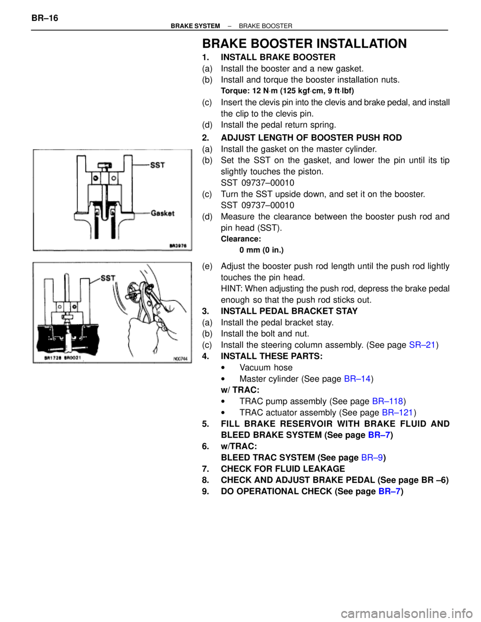
2. ADJUST LENGTH OF BOOSTER PUSH ROD
(a) Install the gasket on the master cylinder.
(b) Set the SST on the gasket, and lower the pin until its tip
slightly touches the piston.
SST 09737±00010
(c) Turn the SST upside down, and set it on the booster.
SST 09737±00010
(d) Measure the clearance between the booster push rod and
pin head (SST).
Clearance:
0 mm (0 in.)
(e) Adjust the booster push rod length until the push rod lightly
touches the pin head.
HINT: When adjusting the push rod, depress the brake pedal
enough so that the push rod sticks out.
3. INSTALL PEDAL BRACKET STAY
(a) Install the pedal bracket stay.
(b) Install the bolt and nut.
(c) Install the steering column assembly. (See page SR±21)
4. INSTALL THESE PARTS:
wVacuum hose
wMaster cylinder (See page BR±14)
w/ TRAC:
wTRAC pump assembly (See page BR±118)
wTRAC actuator assembly (See page BR±121)
5. FILL BRAKE RESERVOIR WITH BRAKE FLUID AND
BLEED BRAKE SYSTEM (See page BR±7)
6. w/TRAC:
BLEED TRAC SYSTEM (See page BR±9)
7. CHECK FOR FLUID LEAKAGE
8. CHECK AND ADJUST BRAKE PEDAL (See page BR ±6)
9. DO OPERATIONAL CHECK (See page BR±7) BR±16
± BRAKE SYSTEMBRAKE BOOSTER
Page 887 of 2543
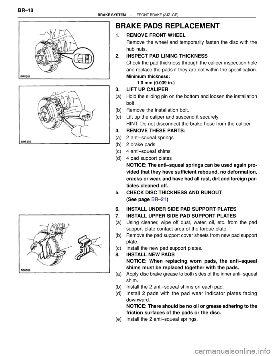
BRAKE PADS REPLACEMENT
1. REMOVE FRONT WHEEL
Remove the wheel and temporarily fasten the disc with the
hub nuts.
2. INSPECT PAD LINING THICKNESS
Check the pad thickness through the caliper inspection hole
and replace the pads if they are not within the specification.
Minimum thickness:
1.0 mm (0.039 in.)
3. LIFT UP CALIPER
(a) Hold the sliding pin on the bottom and loosen the installation
bolt.
(b) Remove the installation bolt.
(c) Lift up the caliper and suspend it securely.
HINT: Do not disconnect the brake hose from the caliper.
4. REMOVE THESE PARTS:
(a) 2 anti±squeal springs
(b) 2 brake pads
(c) 4 anti±squeal shims
(d) 4 pad support plates
NOTICE: The anti±squeal springs can be used again pro-
vided that they have sufficient rebound, no deformation,
cracks or wear, and have had all rust, dirt and foreign par-
ticles cleaned off.
5. CHECK DISC THICKNESS AND RUNOUT
(See page BR±21)
6. INSTALL UNDER SIDE PAD SUPPORT PLATES
7. INSTALL UPPER SIDE PAD SUPPORT PLATES
(a) Using cleaner, wipe off dust, water, oil, etc. from the pad
support plate contact area of the torque plate.
(b) Remove the pad support cover sheets from new pad support
plate.
(c) Install the new pad support plates.
8. INSTALL NEW PADS
NOTICE: When replacing worn pads, the anti±squeal
shims must be replaced together with the pads.
(a) Apply disc brake grease to both sides of the inner anti±squeal
shim.
(b) Install the 2 anti±squeal shims on each pad.
(d) Install 2 pads with the pad wear indicator plates facing
downward.
NOTICE: There should be no oil or grease adhering to the
friction surfaces of the pads or the disc.
(e) Install the 2 anti±squeal springs. BR±18
± BRAKE SYSTEMFRONT BRAKE (2JZ±GE)
Page 888 of 2543
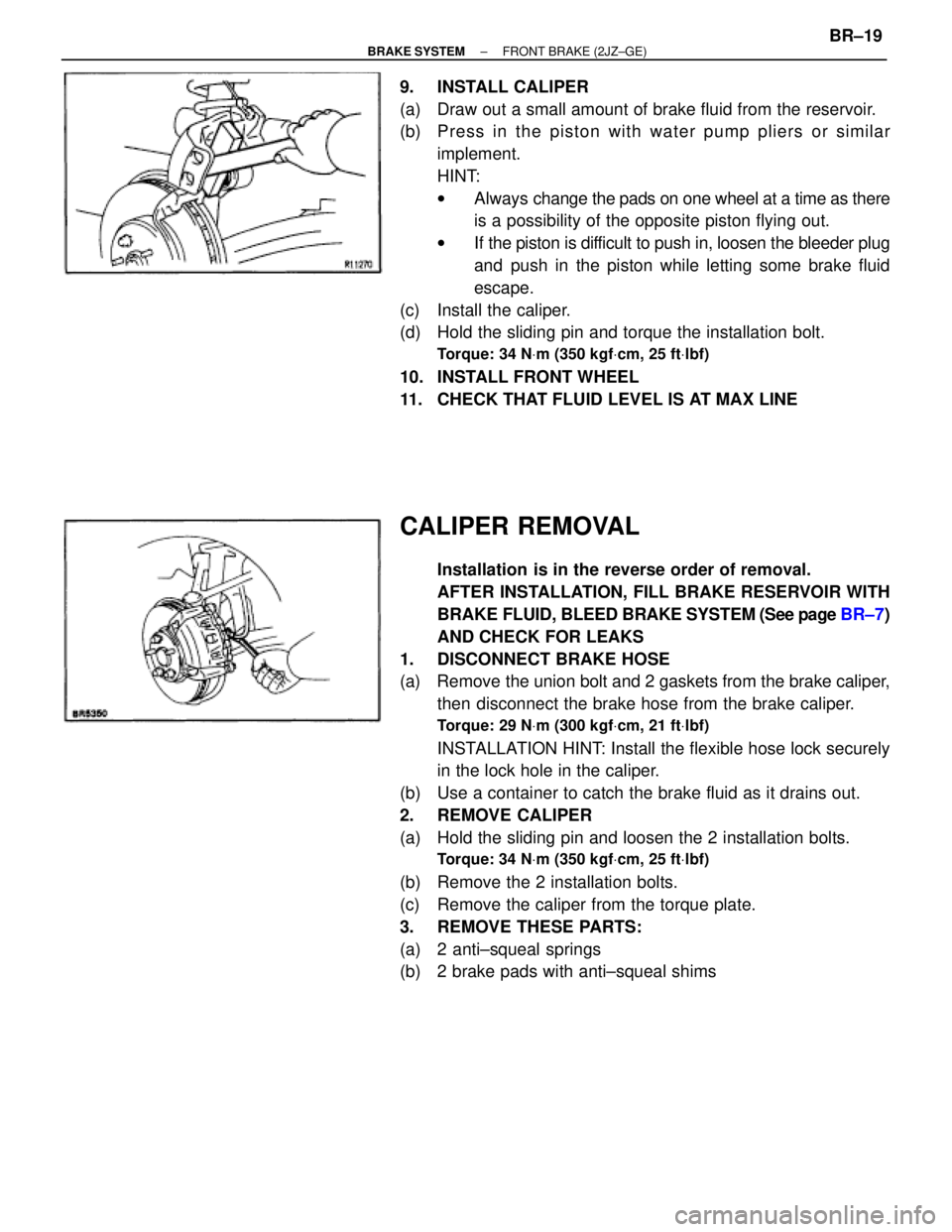
9. INSTALL CALIPER
(a) Draw out a small amount of brake fluid from the reservoir.
(b) P re ss in th e pisto n with wa te r pu mp plie rs or simila r
implement.
HINT:
wAlways change the pads on one wheel at a time as there
is a possibility of the opposite piston flying out.
wIf the piston is difficult to push in, loosen the bleeder plug
and push in the piston while letting some brake fluid
escape.
(c) Install the caliper.
(d) Hold the sliding pin and torque the installation bolt.
Torque: 34 NVm (350 kgfVcm, 25 ftVlbf)
10. INSTALL FRONT WHEEL
11. CHECK THAT FLUID LEVEL IS AT MAX LINE
CALIPER REMOVAL
Installation is in the reverse order of removal.
AFTER INSTALLATION, FILL BRAKE RESERVOIR WITH
BRAKE FLUID, BLEED BRAKE SYSTEM (See page BR±7)
AND CHECK FOR LEAKS
1. DISCONNECT BRAKE HOSE
(a) Remove the union bolt and 2 gaskets from the brake caliper,
then disconnect the brake hose from the brake caliper.
Torque: 29 NVm (300 kgfVcm, 21 ftVlbf)
INSTALLATION HINT: Install the flexible hose lock securely
in the lock hole in the caliper.
(b) Use a container to catch the brake fluid as it drains out.
2. REMOVE CALIPER
(a) Hold the sliding pin and loosen the 2 installation bolts.
Torque: 34 NVm (350 kgfVcm, 25 ftVlbf)
(b) Remove the 2 installation bolts.
(c) Remove the caliper from the torque plate.
3. REMOVE THESE PARTS:
(a) 2 anti±squeal springs
(b) 2 brake pads with anti±squeal shims
± BRAKE SYSTEMFRONT BRAKE (2JZ±GE)BR±19
Page 889 of 2543
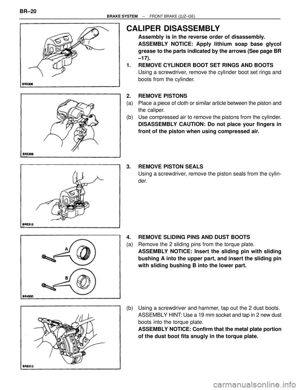
CALIPER DISASSEMBLY
Assembly is in the reverse order of disassembly.
ASSEMBLY NOTICE: Apply lithium soap base glycol
grease to the parts indicated by the arrows (See page BR
±17).
1. REMOVE CYLINDER BOOT SET RINGS AND BOOTS
Using a screwdriver, remove the cylinder boot set rings and
boots from the cylinder.
2. REMOVE PISTONS
(a) Place a piece of cloth or similar article between the piston and
the caliper.
(b) Use compressed air to remove the pistons from the cylinder.
DISASSEMBLY CAUTION: Do not place your fingers in
front of the piston when using compressed air.
3. REMOVE PISTON SEALS
Using a screwdriver, remove the piston seals from the cylin-
der.
4. REMOVE SLIDING PINS AND DUST BOOTS
(a) Remove the 2 sliding pins from the torque plate.
ASSEMBLY NOTICE: Insert the sliding pin with sliding
bushing A into the upper part, and insert the sliding pin
with sliding bushing B into the lower part.
(b) Using a screwdriver and hammer, tap out the 2 dust boots.
ASSEMBLY HINT: Use a 19 mm socket and tap in 2 new dust
boots into the torque plate.
ASSEMBLY NOTICE: Confirm that the metal plate portion
of the dust boot fits snugly in the torque plate. BR±20
± BRAKE SYSTEMFRONT BRAKE (2JZ±GE)