Page 1036 of 2543

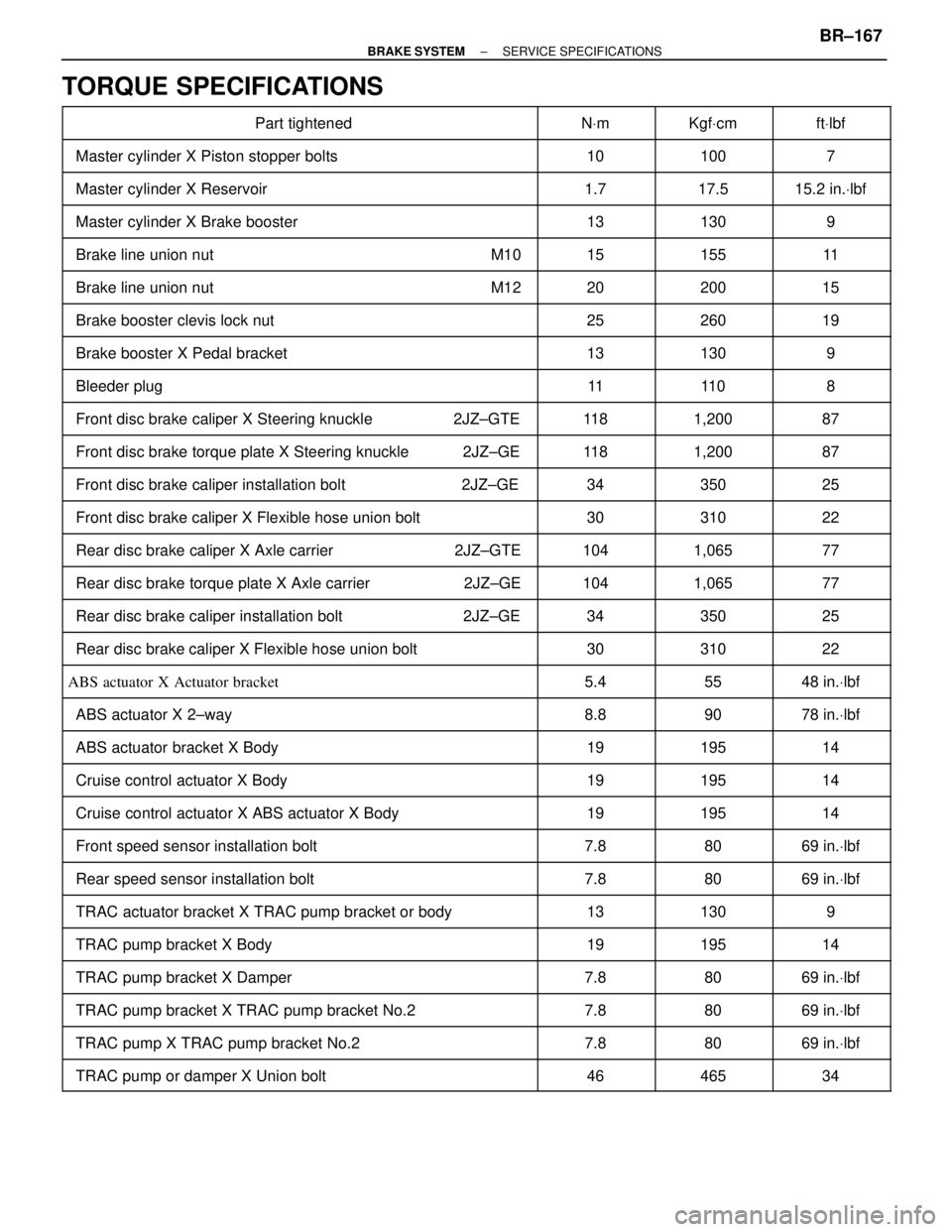
TORQUE SPECIFICATIONS
��������������������� ���������������������Part tightened������ ������NVm������ ������KgfVcm������ ������ftVlbf��������������������� �
�������������������� ���������������������Master cylinder X Piston stopper bolts
������ �
����� ������10
������ �
����� ������100
������ �
����� ������7
��������������������� ���������������������Master cylinder X Reservoir������ ������1.7������ ������17.5������ ������15.2 in.Vlbf
��������������������� ���������������������Master cylinder X Brake booster������ ������13������ ������130������ ������9��������������������� �
�������������������� ���������������������Brake line union nut M10
������ �
����� ������15
������ �
����� ������155
������ �
����� ������11
��������������������� ���������������������Brake line union nut M12������ ������20������ ������200������ ������15
��������������������� �
�������������������� ���������������������Brake booster clevis lock nut������ �
����� ������25������ �
����� ������260������ �
����� ������19
��������������������� ���������������������Brake booster X Pedal bracket������ ������13������ ������130������ ������9
��������������������� ���������������������Bleeder plug������ ������11������ ������11 0������ ������8��������������������� �
�������������������� ���������������������Front disc brake caliper X Steering knuckle 2JZ±GTE
������ �
����� ������11 8
������ �
����� ������1,200
������ �
����� ������87
��������������������� ���������������������Front disc brake torque plate X Steering knuckle 2JZ±GE������ ������11 8������ ������1,200������ ������87
��������������������� ���������������������Front disc brake caliper installation bolt 2JZ±GE������ ������34������ ������350������ ������25��������������������� �
�������������������� ���������������������Front disc brake caliper X Flexible hose union bolt
������ �
����� ������30
������ �
����� ������310
������ �
����� ������22
��������������������� ���������������������Rear disc brake caliper X Axle carrier 2JZ±GTE������ ������104������ ������1,065������ ������77
��������������������� �
�������������������� ���������������������Rear disc brake torque plate X Axle carrier 2JZ±GE������ �
����� ������104������ �
����� ������1,065������ �
����� ������77
��������������������� ���������������������Rear disc brake caliper installation bolt 2JZ±GE������ ������34������ ������350������ ������25
��������������������� ���������������������Rear disc brake caliper X Flexible hose union bolt������ ������30������ ������310������ ������22��������������������� �
�������������������� ���������������������ABS actuator X Actuator bracket
������ �
����� ������5.4
������ �
����� ������55
������ �
����� ������48 in.Vlbf
��������������������� ���������������������ABS actuator X 2±way������ ������8.8������ ������90������ ������78 in.Vlbf
��������������������� ���������������������ABS actuator bracket X Body������ ������19������ ������195������ ������14��������������������� �
�������������������� ���������������������Cruise control actuator X Body
������ �
����� ������19
������ �
����� ������195
������ �
����� ������14
��������������������� ���������������������Cruise control actuator X ABS actuator X Body������ ������19������ ������195������ ������14
��������������������� �
�������������������� ���������������������Front speed sensor installation bolt������ �
����� ������7.8������ �
����� ������80������ �
����� ������69 in.Vlbf
��������������������� ���������������������Rear speed sensor installation bolt������ ������7.8������ ������80������ ������69 in.Vlbf
��������������������� ���������������������TRAC actuator bracket X TRAC pump bracket or body������ ������13������ ������130������ ������9��������������������� �
�������������������� ���������������������TRAC pump bracket X Body
������ �
����� ������19
������ �
����� ������195
������ �
����� ������14
��������������������� ���������������������TRAC pump bracket X Damper������ ������7.8������ ������80������ ������69 in.Vlbf
��������������������� ���������������������TRAC pump bracket X TRAC pump bracket No.2������ ������7.8������ ������80������ ������69 in.Vlbf��������������������� �
�������������������� ���������������������TRAC pump X TRAC pump bracket No.2
������ �
����� ������7.8
������ �
����� ������80
������ �
����� ������69 in.Vlbf
��������������������� ���������������������TRAC pump or damper X Union bolt������ ������46������ ������465������ ������34
± BRAKE SYSTEMSERVICE SPECIFICATIONSBR±167
Page 1039 of 2543

EQUIPMENT
������������������ ������������������Battery specific gravity gauge������������������� �������������������Except maintenance±free battery
������������������ ������������������Torque wrench������������������� �������������������
������������������ ������������������Vernier calipers������������������� �������������������Rotor (Slip ring)
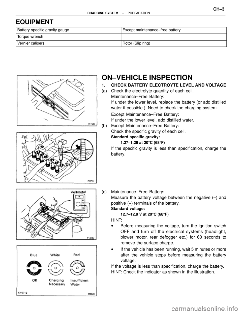
ON±VEHICLE INSPECTION
1. CHECK BATTERY ELECTROYTE LEVEL AND VOLTAGE
(a) Check the electrolyte quantity of each cell.
Maintenance±Free Battery:
If under the lower level, replace the battery (or add distilled
water if possible.). Need to check the charging system.
Except Maintenance±Free Battery:
If under the lower level, add distilled water.
(b) Except Maintenance±Free Battery:
Check the specific gravity of each cell.
Standard specific gravity:
1.27±1.29 at 205C (685F)
If the specific gravity is less than specification, charge the
battery.
(c) Maintenance±Free Battery:
Measure the battery voltage between the negative (±) and
positive (+) terminals of the battery.
Standard voltage:
12.7±12.9 V at 205C (685F)
HINT:
wBefore measuring the voltage, turn the ignition switch
OFF and turn off the electrical systems (headlight,
blower motor, rear defogger etc.) for 60 seconds to
remove the surface charge.
wIf the vehicle has been running, wait 5 minutes or more
after the vehicle stops before measuring the battery
voltage.
If the voltage is less than specification, charge the battery.
HINT: Check the indicator as shown in the illustration.
± CHARGING SYSTEMPREPARATIONCH±3
Page 1040 of 2543

EQUIPMENT
������������������ ������������������Battery specific gravity gauge������������������� �������������������Except maintenance±free battery
������������������ ������������������Torque wrench������������������� �������������������
������������������ ������������������Vernier calipers������������������� �������������������Rotor (Slip ring)
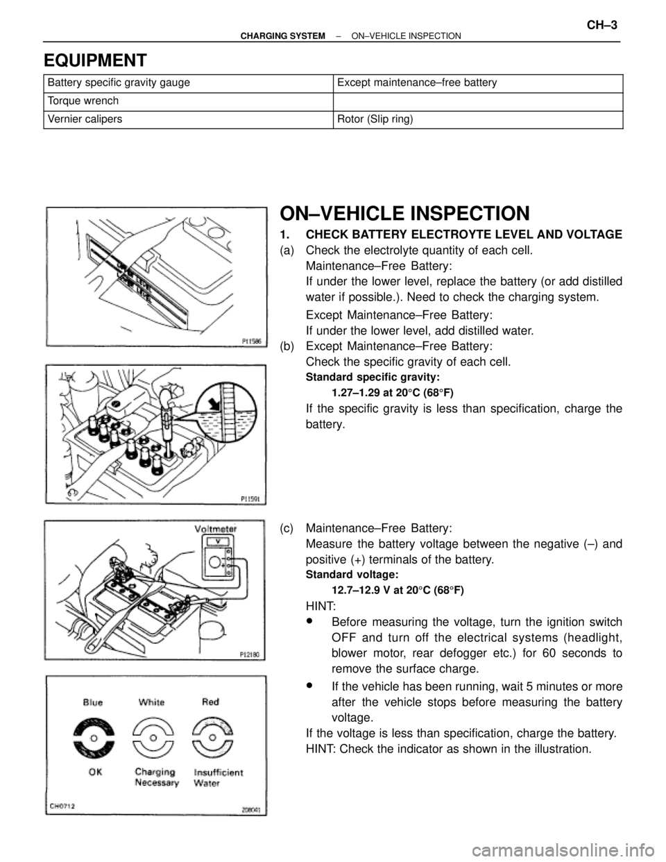
ON±VEHICLE INSPECTION
1. CHECK BATTERY ELECTROYTE LEVEL AND VOLTAGE
(a) Check the electrolyte quantity of each cell.
Maintenance±Free Battery:
If under the lower level, replace the battery (or add distilled
water if possible.). Need to check the charging system.
Except Maintenance±Free Battery:
If under the lower level, add distilled water.
(b) Except Maintenance±Free Battery:
Check the specific gravity of each cell.
Standard specific gravity:
1.27±1.29 at 205C (685F)
If the specific gravity is less than specification, charge the
battery.
(c) Maintenance±Free Battery:
Measure the battery voltage between the negative (±) and
positive (+) terminals of the battery.
Standard voltage:
12.7±12.9 V at 205C (685F)
HINT:
wBefore measuring the voltage, turn the ignition switch
OFF and turn off the electrical systems (headlight,
blower motor, rear defogger etc.) for 60 seconds to
remove the surface charge.
wIf the vehicle has been running, wait 5 minutes or more
after the vehicle stops before measuring the battery
voltage.
If the voltage is less than specification, charge the battery.
HINT: Check the indicator as shown in the illustration.
± CHARGING SYSTEMON±VEHICLE INSPECTIONCH±3
Page 1045 of 2543
GENERATOR REMOVAL
Installation is in the reverse order of removal.
1. REMOVE ENGINE UNDER COVER
2. 2JZ±GTE:
REMOVE NO.2 AIR TUBE FOR CAC
3. REMOVE NO.2 FAN SHROUD
4. 2JZ±GTE M/T:
REMOVE DRIVE BELT TENSIONER DAMPER
Torque: 20 NVm (200 kgfVcm, 14 ftVlbf)
5. REMOVE DRIVE BELT
6. REMOVE GENERATOR
(a) Disconnect the generator connector.
(b) Re mo ve th e rubber cap and nut, and disconnect the
generator wire.
(c) Disconnect the generator wire clamp from the wire clip on the
generator.
(d) A/T:
Remove the bolt and pipe clamp, and disconnect the 2 oil
cooler pipes from the generator.
(e) Remove the bolt, nut, pipe bracket and generator.
Torque: 37 NVm (380 kgfVcm, 27 ftVlbf)
CH±8± CHARGING SYSTEMGENERATOR
Page 1048 of 2543
3. REMOVE WIRE CLIP
Remove the nut and wire clip.
4. REMOVE RECTIFIER HOLDER
(a) Remove the 4 screws and rectifier holder.
(b) Remove the 4 rubber insulators.
5. REMOVE PULLEY
(a) Hold SST (A) with a torque wrench, and tighten SST (B)
clockwise to the specified torque.
SST 09820±63010
Torque: 39 NVm (400 kgfVcm, 29 ftVlbf)
(b) Check that SST (A) is secured to the rotor shaft.
(c) Mount SST (C) in a vise.
(D) Insert SST (B) into SST (C), and attach the pulley nut to SST
(C).
± CHARGING SYSTEMGENERATORCH±11
Page 1054 of 2543
(b) Using a 29 mm socket wrench and press, slowly press in the
rectifier end frame.
(c) Install the 3 nuts.
Torque: 4.5 NVm (46 kgfVcm, 40 in.Vlbf)
4. INSTALL PULLEY
(a) Install the pulley to the rotor shaft by tightening the pulley nut
by hand.
(b) Hold SST (A) with a torque wrench, and tighten SST (b)
clockwise to the specified torque.
SST 09820±63010
Torque: 39 NVm (400 kgfVcm, 29 ftVlbf)
(c) Check that SST (A) is secured to the pulley shaft.
(d) Mount SST (C) in a vise.
(e) Insert SST (B) into SST (C), and attach the pulley nut to SST
(C).
(f) To torque the pulley nut, turn SST (A) in the direction shown
in the illustration.
Torque: 110 NVm (1,125 kgfVcm, 81 ftVlbf)
(g) Remove the generator from SST (C). CH±17
± CHARGING SYSTEMGENERATOR
Page 1055 of 2543
(h) Turn SST (B), and remove SST (A and B).
5. INSTALL RECTIFIER HOLDER
(a) Install the 4 rubber insulators on the lead wires.
(b) Install the rectifier holder while pushing it with the 4 screws.
Torque: 2.0 NVm (20 kgfVcm, 17 in.Vlbf)
6. INSTALL WIRE CLIP
Install the wire clip with the nut.
Torque: 4.5 NVm (46 kgfVcm, 40 in.Vlbf)
7. INSTALL VOLTAGE REGULATOR AND BRUSH HOLDER
(a) Place the seal plate on the rectifier end frame.
± CHARGING SYSTEMGENERATORCH±18
Page 1056 of 2543
(b) Place the voltage regulator and brush holder on the rectifier
end frame.
NOTICE: Be careful of the holder installation direction.
(c) Install the 5 screws until there is a clearance of approx. 1 mm
(0.04 in.) between the brush Holder and voltage regulator.
(d) Place the brush holder cover on the brush holder.
8. INSTALL REAR END COVER
(a) Install the end cover and plate terminal with the bolt and 3
nuts.
Torque:
Nut
4.5 NVm (46 kgfVcm, 40 in.Vlbf)
Bolt
3.9 NVm (40 kgfVcm, 35 in.Vlbf)
(b) Install the terminal insulator with the nut.
Torque: 6.5 NVm (66 kgfVcm, 58 in.Vlbf)
9. CHECK THAT ROTOR ROTATES SMOOTHLY CH±19
± CHARGING SYSTEMGENERATOR