Page 902 of 2543
3. REMOVE CALIPER
Remove the 2 mounting bolts and caliper.
Torque: 104 NVm (1,065 kgfVcm, 77 ftVlbf)
4. REMOVE THESE PARTS:
(a) Clip
(b) 2 pins
(c) Anti±rattle spring
(d) 2 pads
(e) 4 anti±squeal shims
CALIPER DISASSEMBLY
Assembly is in the reverse order of disassembly.
ASSEMBLY NOTICE: Apply lithium soap base glycol
grease to the parts indicated by the arrows (See page BR
±31)
1. REMOVE CYLINDER BOOT SET RINGS AND BOOTS
Using a screwdriver, remove the 2 cylinder boot set rings and
2 boots.
2. REMOVE PISTONS FROM CYLINDER
(a) Prepare a wooden plate to hold the pistons.
(b) Place the plate between the pistons and insert a pad on one
side.
(c) Use compressed air to remove the pistons alternately from
the caliper.
DISASSEMBLY CAUTION: Do not place your fingers in
front of the pistons when using compressed air.
3. REMOVE PISTON SEALS
Using a screwdriver, remove the 2 seals from the cylinder.
± BRAKE SYSTEMREAR BRAKE (2JZ±GTE)BR±33
Page 903 of 2543

REAR BRAKE COMPONENTS
INSPECTION AND REPAIR
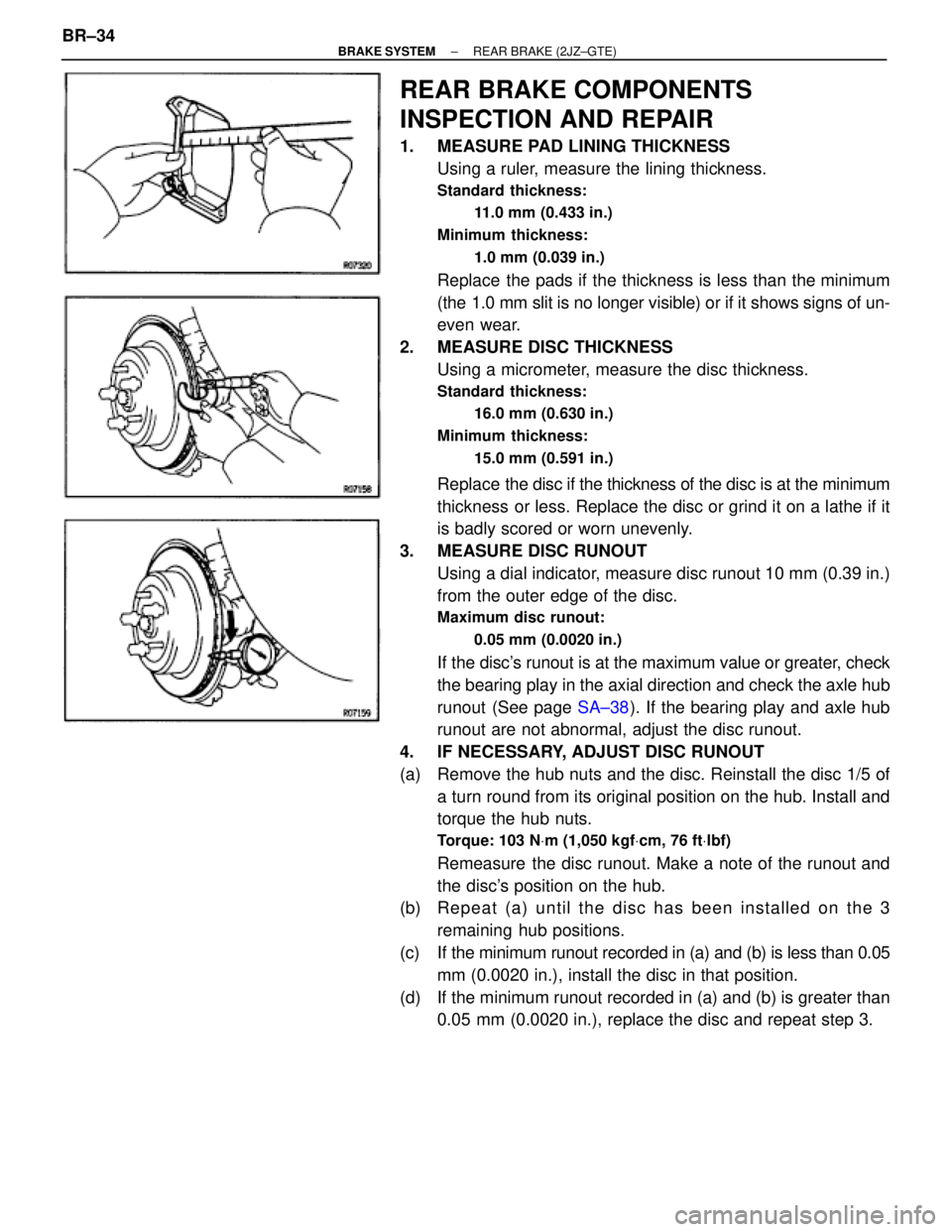
1. MEASURE PAD LINING THICKNESS
Using a ruler, measure the lining thickness.
Standard thickness:
11.0 mm (0.433 in.)
Minimum thickness:
1.0 mm (0.039 in.)
Replace the pads if the thickness is less than the minimum
(the 1.0 mm slit is no longer visible) or if it shows signs of un-
even wear.
2. MEASURE DISC THICKNESS
Using a micrometer, measure the disc thickness.
Standard thickness:
16.0 mm (0.630 in.)
Minimum thickness:
15.0 mm (0.591 in.)
Replace the disc if the thickness of the disc is at the minimum
thickness or less. Replace the disc or grind it on a lathe if it
is badly scored or worn unevenly.
3. MEASURE DISC RUNOUT
Using a dial indicator, measure disc runout 10 mm (0.39 in.)
from the outer edge of the disc.
Maximum disc runout:
0.05 mm (0.0020 in.)
If the disc's runout is at the maximum value or greater, check
the bearing play in the axial direction and check the axle hub
runout (See page SA±38). If the bearing play and axle hub
runout are not abnormal, adjust the disc runout.
4. IF NECESSARY, ADJUST DISC RUNOUT
(a) Remove the hub nuts and the disc. Reinstall the disc 1/5 of
a turn round from its original position on the hub. Install and
torque the hub nuts.
Torque: 103 NVm (1,050 kgfVcm, 76 ftVlbf)
Remeasure the disc runout. Make a note of the runout and
the disc's position on the hub.
(b) Repeat (a) until the disc has been installed on the 3
remaining hub positions.
(c) If the minimum runout recorded in (a) and (b) is less than 0.05
mm (0.0020 in.), install the disc in that position.
(d) If the minimum runout recorded in (a) and (b) is greater than
0.05 mm (0.0020 in.), replace the disc and repeat step 3. BR±34
± BRAKE SYSTEMREAR BRAKE (2JZ±GTE)
Page 908 of 2543

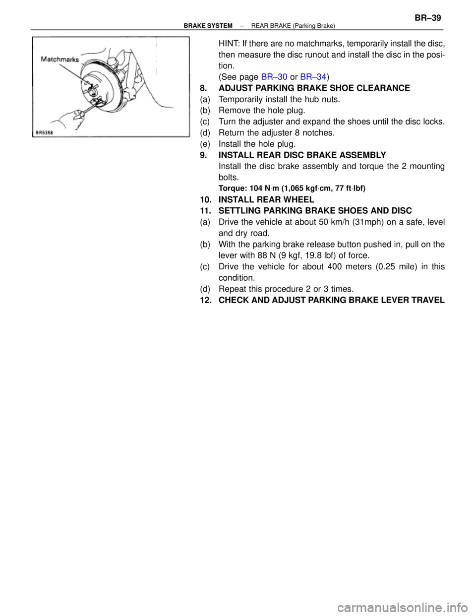
HINT: If there are no matchmarks, temporarily install the disc,
then measure the disc runout and install the disc in the posi-
tion.
(See page BR±30 or BR±34)
8. ADJUST PARKING BRAKE SHOE CLEARANCE
(a) Temporarily install the hub nuts.
(b) Remove the hole plug.
(c) Turn the adjuster and expand the shoes until the disc locks.
(d) Return the adjuster 8 notches.
(e) Install the hole plug.
9. INSTALL REAR DISC BRAKE ASSEMBLY
Install the disc brake assembly and torque the 2 mounting
bolts.
Torque: 104 NVm (1,065 kgfVcm, 77 ftVlbf)
10. INSTALL REAR WHEEL
11. SETTLING PARKING BRAKE SHOES AND DISC
(a) Drive the vehicle at about 50 km/h (31mph) on a safe, level
and dry road.
(b) With the parking brake release button pushed in, pull on the
lever with 88 N (9 kgf, 19.8 lbf) of force.
(c) Drive the vehicle for about 400 meters (0.25 mile) in this
condition.
(d) Repeat this procedure 2 or 3 times.
12. CHECK AND ADJUST PARKING BRAKE LEVER TRAVEL
± BRAKE SYSTEMREAR BRAKE (Parking Brake)BR±39
Page 913 of 2543

ABS ACTUATOR REMOVAL
Installation is in the reverse order of removal.
AFTER INSTALLATION, BLEED BRAKE SYSTEM (See
page BR±7) AND BLEED TRAC SYSTEM (See page BR±9)
1. REMOVE CRUISE CONTROL ACTUATOR
Remove the 3 bolts and cruise control actuator.
Torque:
Cruise control actuator X Body
13 NVm (130 kgfVcm, 9 ftVlbf)
Cruise control actuator X ABS actuator X Body
19 NVm (195 kgfVcm, 14 ftVlbf)
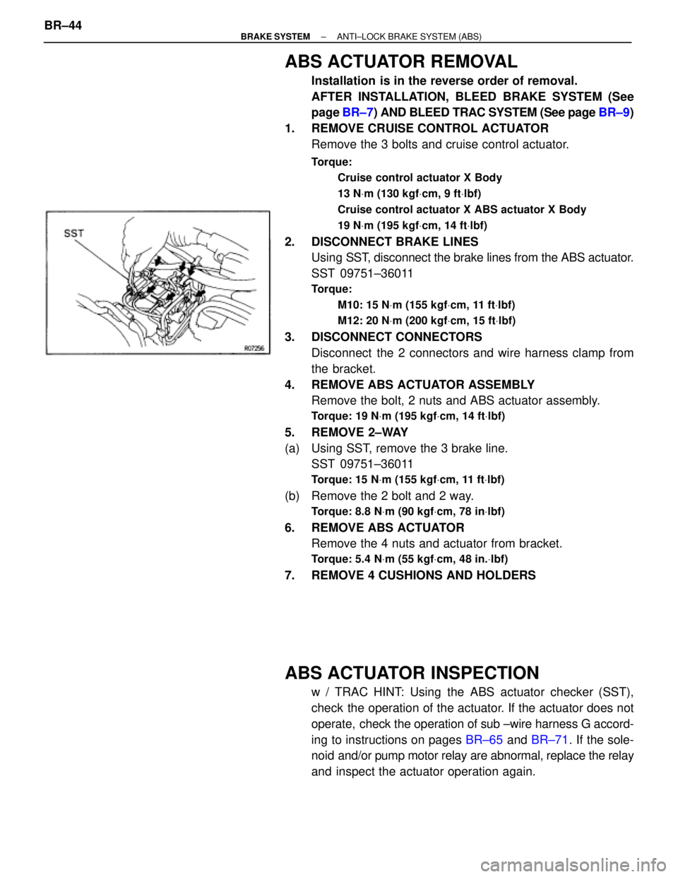
2. DISCONNECT BRAKE LINES
Using SST, disconnect the brake lines from the ABS actuator.
SST 09751±36011
Torque:
M10: 15 NVm (155 kgfVcm, 11 ftVlbf)
M12: 20 NVm (200 kgfVcm, 15 ftVlbf)
3. DISCONNECT CONNECTORS
Disconnect the 2 connectors and wire harness clamp from
the bracket.
4. REMOVE ABS ACTUATOR ASSEMBLY
Remove the bolt, 2 nuts and ABS actuator assembly.
Torque: 19 NVm (195 kgfVcm, 14 ftVlbf)
5. REMOVE 2±WAY
(a) Using SST, remove the 3 brake line.
SST 09751±36011
Torque: 15 NVm (155 kgfVcm, 11 ftVlbf)
(b) Remove the 2 bolt and 2 way.
Torque: 8.8 NVm (90 kgfVcm, 78 inVlbf)
6. REMOVE ABS ACTUATOR
Remove the 4 nuts and actuator from bracket.
Torque: 5.4 NVm (55 kgfVcm, 48 in.Vlbf)
7. REMOVE 4 CUSHIONS AND HOLDERS
ABS ACTUATOR INSPECTION
w / TRAC HINT: Using the ABS actuator checker (SST),
check the operation of the actuator. If the actuator does not
operate, check the operation of sub ±wire harness G accord-
ing to instructions on pages BR±65 and BR±71. If the sole-
noid and/or pump motor relay are abnormal, replace the relay
and inspect the actuator operation again. BR±44
± BRAKE SYSTEMANTI±LOCK BRAKE SYSTEM (ABS)
Page 917 of 2543
FRONT SPEED SENSOR
COMPONENTS
FRONT SPEED SENSOR REMOVAL
Installation is in the reverse order of removal.
AFTER INSTALLATION, CHECK SPEED SENSOR SIG-
NAL (See page BR±62)
1. DISCONNECT CONNECTOR
(a) Remove the front fender splash shield.
(b) Disconnect the speed sensor connector.
2. REMOVE SPEED SENSOR
(a) Remove the 3 clamp bolts holding the sensor harness to the
body and upper suspension arm.
Torque: 5.4 NVm (55 kgfVcm, 48 in.Vlbf)
(b) Remove the speed sensor from the steering knuckle.
Torque: 7.8 NVm (80 kgfVcm, 69 in.Vlbf)
(c) Remove the O±ring from the speed sensor. BR±48
± BRAKE SYSTEMANTI±LOCK BRAKE SYSTEM (ABS)
Page 918 of 2543
REAR SPEED SENSOR
COMPONENTS
REAR SPEED SENSOR REMOVAL
Installation is in the reverse order of removal.
AFTER INSTALLATION, CHECK SPEED SENSOR SIG-
NAL (See page BR±62)
1. DISCONNECT SPEED SENSOR CONNECTOR
(a) Remove the rear seat cushion and seat back.
(b) Remove the quarter trim panel.
(c) Disconnect the speed sensor connector, and pull out the
sensor wire harness with the grommet.
2. REMOVE SPEED SENSOR
(a) Remove the 2 clamp bolts holding the sensor wire harness
to the body and upper arm.
Torque: 5.4 NVm (55 kgfVcm, 48 in.Vlbf)
(b) Remove the speed sensor from the axle carrier.
Torque: 7.8 NVm (80 kgfVcm, 69 in.Vlbf)
± BRAKE SYSTEMANTI±LOCK BRAKE SYSTEM (ABS)BR±49
Page 987 of 2543

TRAC PUMP REMOVAL
Installation is in the reverse order of removal.
AFTER INSTALLATION, BLEED BRAKE SYSTEM
(See page BR±7) AND BLEED TRAC SYSTEM (See page
BR±9)
1. REMOVE TRAC ACTUATOR
(See page BR±121)
2. REMOVE BRAKE MASTER CYLINDER
(See page BR±11)
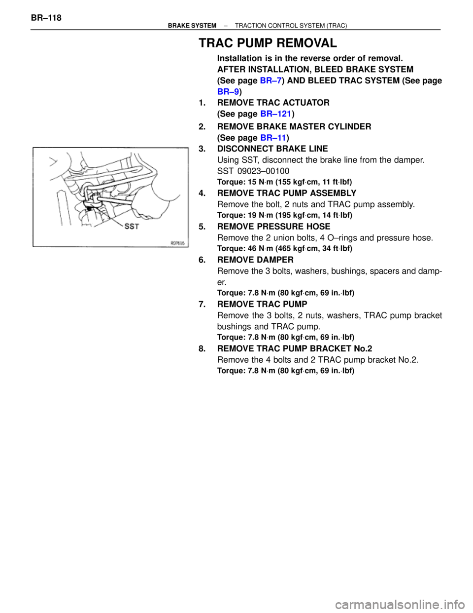
3. DISCONNECT BRAKE LINE
Using SST, disconnect the brake line from the damper.
SST 09023±00100
Torque: 15 NVm (155 kgfVcm, 11 ftVlbf)
4. REMOVE TRAC PUMP ASSEMBLY
Remove the bolt, 2 nuts and TRAC pump assembly.
Torque: 19 NVm (195 kgfVcm, 14 ftVlbf)
5. REMOVE PRESSURE HOSE
Remove the 2 union bolts, 4 O±rings and pressure hose.
Torque: 46 NVm (465 kgfVcm, 34 ftVlbf)
6. REMOVE DAMPER
Remove the 3 bolts, washers, bushings, spacers and damp-
er.
Torque: 7.8 NVm (80 kgfVcm, 69 in.Vlbf)
7. REMOVE TRAC PUMP
Remove the 3 bolts, 2 nuts, washers, TRAC pump bracket
bushings and TRAC pump.
Torque: 7.8 NVm (80 kgfVcm, 69 in.Vlbf)
8. REMOVE TRAC PUMP BRACKET No.2
Remove the 4 bolts and 2 TRAC pump bracket No.2.
Torque: 7.8 NVm (80 kgfVcm, 69 in.Vlbf)
BR±118± BRAKE SYSTEMTRACTION CONTROL SYSTEM (TRAC)
Page 990 of 2543
TRAC ACTUATOR REMOVAL
Installation is in the reverse order of removal.
AFTER INSTALLATION, BLEED BRAKE SYSTEM (See
page BR±7) AND BLEED TRAC SYSTEM (See page BR±9)
1. DISCONNECT BRAKE LINES
Using SST, disconnect the brake lines from the TRAC actua-
tor.
SST 09751±36011
Torque: 15 NVm (155 kgfVcm, 11 ftVlbf)
2. REMOVE TRAC ACTUATOR ASSEMBLY
Remove the 2 bolts, nut and TRAC actuator assembly.
Torque: 13 NVm (130 kgfVcm, 9 ftVlbf)
3. REMOVE TRAC ACTUATOR
Remove the 3 bolts and actuator from the bracket.
Torque: 13 NVm (130 kgfVcm, 9 ftVlbf)
4. SEPARATE TRAC ACTUATOR BRACKET
Remove the 2 bolts and separate the bracket.
Torque: 13 NVm (130 kgfVcm, 9 ftVlbf)
± BRAKE SYSTEMTRACTION CONTROL SYSTEM (TRAC)BR±121