Page 1252 of 2543
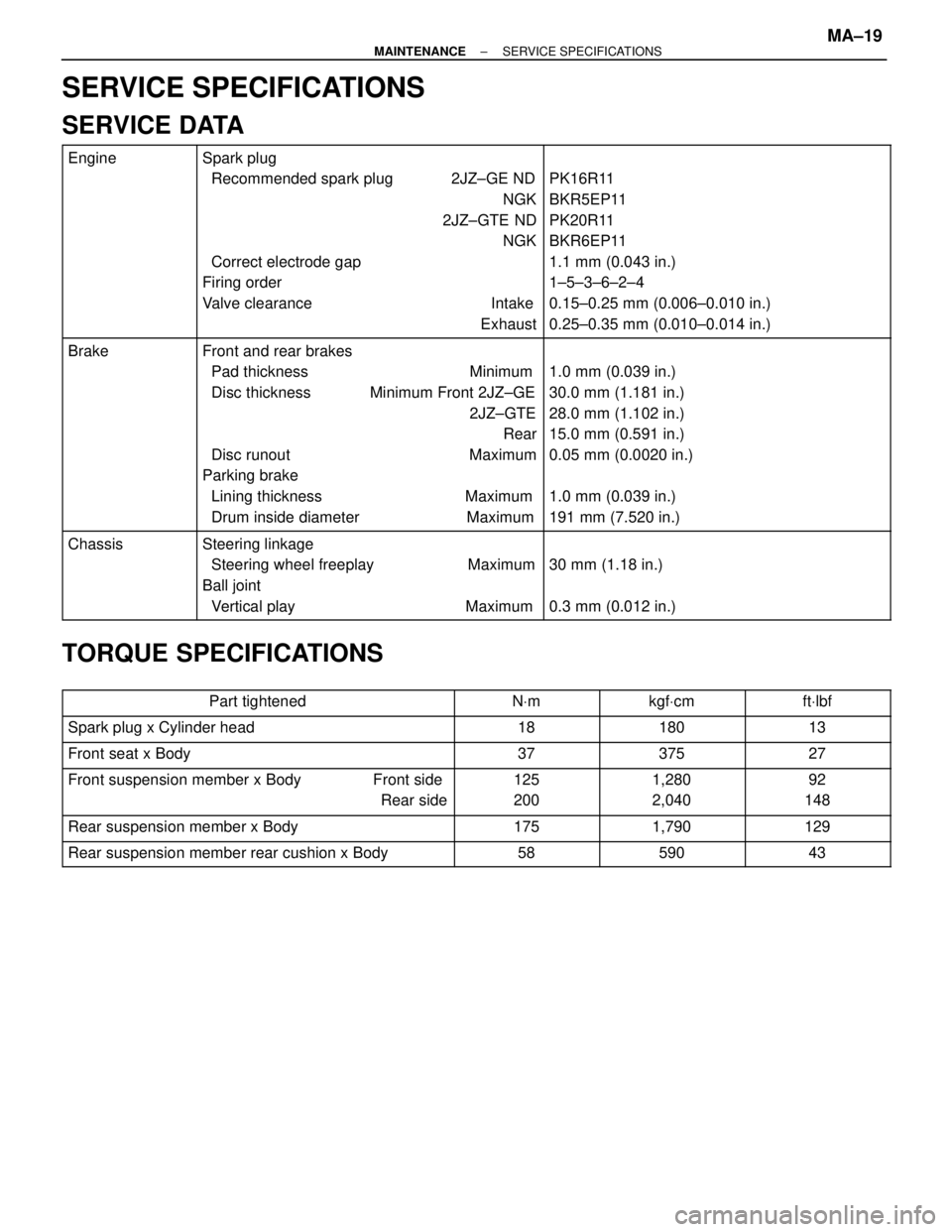
SERVICE SPECIFICATIONS
SERVICE DATA
������� �
������ �
������ �
������ �
������ �
������ �
������ �
������ �������
Engine��������������� �
�������������� �
�������������� �
�������������� �
�������������� �
�������������� �
�������������� �
�������������� ���������������
Spark plug
Recommended spark plug 2JZ±GE ND
NGK
2JZ±GTE ND
NGK
Correct electrode gap
Firing order
Valve clearance Intake
Exhaust���������������� �
��������������� �
��������������� �
��������������� �
��������������� �
��������������� �
��������������� �
��������������� ����������������
PK16R11
BKR5EP11
PK20R11
BKR6EP11
1.1 mm (0.043 in.)
1±5±3±6±2±4
0.15±0.25 mm (0.006±0.010 in.)
0.25±0.35 mm (0.010±0.014 in.)
������� �
������ �
������ �
������ �
������ �
������ �
������ �
������ �������
Brake��������������� �
�������������� �
�������������� �
�������������� �
�������������� �
�������������� �
�������������� �
�������������� ���������������
Front and rear brakes
Pad thickness Minimum
Disc thickness Minimum Front 2JZ±GE
2JZ±GTE
Rear
Disc runout Maximum
Parking brake
Lining thickness Maximum
Drum inside diameter Maximum���������������� �
��������������� �
��������������� �
��������������� �
��������������� �
��������������� �
��������������� �
��������������� ����������������
1.0 mm (0.039 in.)
30.0 mm (1.181 in.)
28.0 mm (1.102 in.)
15.0 mm (0.591 in.)
0.05 mm (0.0020 in.)
1.0 mm (0.039 in.)
191 mm (7.520 in.)
������� �
������ �
������ �������
Chassis��������������� �
�������������� �
�������������� ���������������
Steering linkage
Steering wheel freeplay Maximum
Ball joint
Vertical play Maximum���������������� �
��������������� �
��������������� ����������������
30 mm (1.18 in.)
0.3 mm (0.012 in.)
TORQUE SPECIFICATIONS
����������������� �����������������Part tightened������� �������NVm������� �������kgfVcm������� �������ftVlbf����������������� �
����������������
�����������������
Spark plug x Cylinder head
�������
������� �������18
������� �
������ �������180
������� �
������ �������13
����������������� �����������������Front seat x Body������� �������37������� �������375������� �������27
����������������� �
����������������
�����������������
Front suspension member x Body Front side
Rear side�������
������� �������
125
200������� �
������ �������
1,280
2,040������� �
������ �������
92
148
����������������� �����������������Rear suspension member x Body������� �������175������� �������1,790������� �������129
����������������� �����������������Rear suspension member rear cushion x Body������� �������58������� �������590������� �������43
± MAINTENANCESERVICE SPECIFICATIONSMA±19
Page 1254 of 2543
09308±10010
09308±14010
09309±14040
09330±00021
09950±30010
(09951±03010)
(09953±03010)
(09955±03030)
(09956±03030)
(09954±03010)
Adaptor 20
Lower Plate 130
Arm
Center Bolt
Upper Plate
Puller A Set
Companion Flange Holding Tool
Remover & Replacer D
Replacer Pipe A
Oil Seal Puller
PREPARATION
SST (SPECIAL SERVICE TOOLS)
EQUIPMENT
��������������������� �
�������������������� ���������������������Calipers���������������� �
��������������� ����������������
��������������������� ���������������������Torque wrench���������������� ����������������
LUBRICANT
����������� �����������Item������������� �������������Capacity�������������� ��������������Oil type
����������� �
���������� �����������Manual transmission oil������������� �
������������ �������������1.8 liters (1.9 US qts, 1.6 lmp.qts)�������������� �
������������� ��������������
TOYOTA GEAR OIL V160 or
ESSO ATF DEXRON[D 21065
MT2±2± V160 MANUAL TRANSMISSIONPREPARATION
Page 1258 of 2543
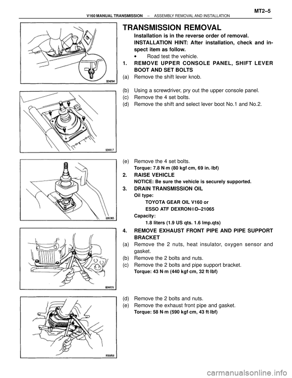
TRANSMISSION REMOVAL
Installation is in the reverse order of removal.
INSTALLATION HINT: After installation, check and in-
spect item as follow.
w Road test the vehicle.
1. REMOVE UPPER CONSOLE PANEL, SHIFT LEVER
BOOT AND SET BOLTS
(a) Remove the shift lever knob.
(b) Using a screwdriver, pry out the upper console panel.
(c) Remove the 4 set bolts.
(d) Remove the shift and select lever boot No.1 and No.2.
(e) Remove the 4 set bolts.
Torque: 7.8 NVm (80 kgfVcm, 69 in.Vlbf)
2. RAISE VEHICLE
NOTICE: Be sure the vehicle is securely supported.
3. DRAIN TRANSMISSION OIL
Oil type:
TOYOTA GEAR OIL V160 or
ESSO ATF DEXRON[D±21065
Capacity:
1.8 liters (1.9 US qts. 1.6 lmp.qts)
4. REMOVE EXHAUST FRONT PIPE AND PIPE SUPPORT
BRACKET
(a) Remove the 2 nuts, heat insulator, oxygen sensor and
gasket.
(b) Remove the 2 bolts and nuts.
(c) Remove the 2 bolts and pipe support bracket.
Torque: 43 NVm (440 kgfVcm, 32 ftVlbf)
(d) Remove the 2 bolts and nuts.
(e) Remove the exhaust front pipe and gasket.
Torque: 58 NVm (590 kgfVcm, 43 ftVlbf)
± V160 MANUAL TRANSMISSIONASSEMBLY REMOVAL AND INSTALLATIONMT2±5
Page 1259 of 2543
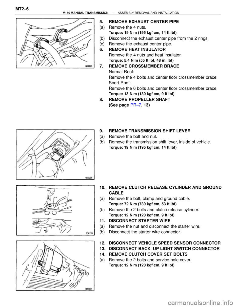
5. REMOVE EXHAUST CENTER PIPE
(a) Remove the 4 nuts.
Torque: 19 NVm (195 kgfVcm, 14 ftVlbf)
(b) Disconnect the exhaust center pipe from the 2 rings.
(c) Remove the exhaust center pipe.
6. REMOVE HEAT INSULATOR
Remove the 4 nuts and heat insulator.
Torque: 5.4 NVm (55 ftVlbf, 48 in.Vlbf)
7. REMOVE CROSSMEMBER BRACE
Normal Roof:
Remove the 4 bolts and center floor crossmember brace.
Sport Roof:
Remove the 6 bolts and center floor crossmember brace.
Torque: 13 NVm (130 kgfVcm, 9 ftVlbf)
8. REMOVE PROPELLER SHAFT
(See page PR±7, 13)
9. REMOVE TRANSMISSION SHIFT LEVER
(a) Remove the bolt and nut.
(b) Remove the transmission shift lever, inside of vehicle.
Torque: 19 NVm (195 kgfVcm, 14 ftVlbf)
10. REMOVE CLUTCH RELEASE CYLINDER AND GROUND
CABLE
(a) Remove the bolt, clamp and ground cable.
Torque: 72 NVm (730 kgfVcm, 53 ftVlbf)
(b) Remove the 2 bolts and clutch release cylinder.
Torque: 12 NVm (120 kgfVcm, 9 ftVlbf)
11. DISCONNECT STARTER WIRE
(a) Remove the nut and disconnect the starter wire.
(b) Disconnect the starter wire connector.
12. DISCONNECT VEHICLE SPEED SENSOR CONNECTOR
13. DISCONNECT BACK±UP LIGHT SWITCH CONNECTOR
14. REMOVE CLUTCH COVER SET BOLTS
(a) Remove the 2 bolts and service hole cover.
Torque: 12 NVm (120 kgfVcm, 9 ftVlbf)
MT2±6± V160 MANUAL TRANSMISSIONASSEMBLY REMOVAL AND INSTALLATION
Page 1260 of 2543
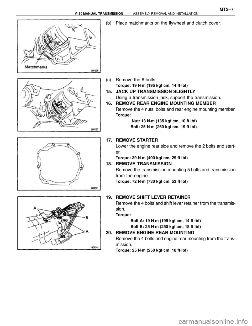
(b) Place matchmarks on the flywheel and clutch cover.
(c) Remove the 6 bolts.
Torque: 19 NVm (195 kgfVcm, 14 ftVlbf)
15. JACK UP TRANSMISSION SLIGHTLY
Using a transmission jack, support the transmission.
16. REMOVE REAR ENGINE MOUNTING MEMBER
Remove the 4 nuts, bolts and rear engine mounting member.
Torque:
VNut: 13 NVm (135 kgfVcm, 10 ftVlbf)
Bolt: 25 NVm (260 kgfVcm, 19 ftVlbf)
17. REMOVE STARTER
Lower the engine rear side and remove the 2 bolts and start-
er.
Torque: 39 NVm (400 kgfVcm, 29 ftVlbf)
18. REMOVE TRANSMISSION
Remove the transmission mounting 5 bolts and transmission
from the engine.
Torque: 72 NVm (730 kgfVcm, 53 ftVlbf)
19. REMOVE SHIFT LEVER RETAINER
Remove the 4 bolts and shift lever retainer from the transmis-
sion.
Torque:
Bolt A: 19 NVm (195 kgfVcm, 14 ftVlbf)
Bolt B: 25 NVm (250 kgfVcm, 18 ftVlbf)
20. REMOVE ENGINE REAR MOUNTING
Remove the 4 bolts and engine rear mounting from the trans-
mission.
Torque: 25 NVm (250 kgfVcm, 18 ftVlbf)
± V160 MANUAL TRANSMISSIONASSEMBLY REMOVAL AND INSTALLATIONMT2±7
Page 1262 of 2543
(e) Using SST, remove the companion flange.
SST 09950±30010 (09951±03010, 09953±03010,
09954±03010, 09955±03030, 09956±03030)
(f) Using SST, remove the oil seal.
SST 09308±10010
(g) Using SST and a hammer, install a new oil seal.
SST 09308±14010, 09309±14040
(h) Heat the companion flange in an oven.
80±90°C (176±194°F)
(i) Apply gear oil to the output shaft and install the companion
flange.
(j) Using SST, install the companion flange to the output shaft.
SST 09950±30010 (09951±03010, 09953±03010,
09954±03010, 09955±03030, 09956±03030)
(k) Using SST to hold the flange, install and torque the lock nut.
SST 09330±00021
Torque: 190 NVm (1,940 kgfVcm, 140 ftVlbf)
± V160 MANUAL TRANSMISSIONOIL SEALSMT2±9
Page 1263 of 2543
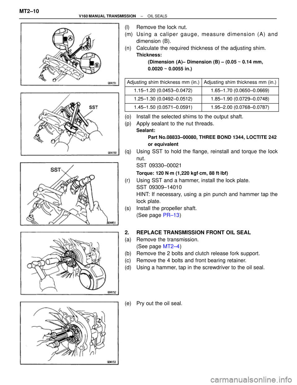
(l) Remove the lock nut.
(m) Using a caliper gauge, measure dimension (A) and
dimension (B).
(n) Calculate the required thickness of the adjusting shim.
Thickness:
(Dimension (A)± Dimension (B) ± (0.05 ~ 0.14 mm,
0.0020 ~ 0.0055 in.)
������������ ������������Adjusting shim thickness mm (in.)����������� �����������Adjusting shim thickness mm (in.)
������������ ������������1 15±1 20 (0 0453±0 0472)1 65±1 70 (0 0650±0 0669)
������������
1.15±1.20 (0.0453±0.0472)1.65±1.70 (0.0650±0.0669)
������������ ������������1 25±1 30 (0 0492±0 0512)1 85±1 90 (0 0729±0 0748)������������1.25±1.30 (0.0492±0.0512)1.85±1.90 (0.0729±0.0748)������������ ������������1 45±1 50 (0 0571±0 0591)1 95±2 00 (0 0768±0 0787)������������1.45±1.50 (0.0571±0.0591)1.95±2.00 (0.0768±0.0787)
(o) Install the selected shims to the output shaft.
(p) Apply sealant to the nut threads.
Sealant:
Part No.08833±00080, THREE BOND 1344, LOCTITE 242
or equivalent
(q) Using SST to hold the flange, reinstall and torque the lock
nut.
SST 09330±00021
Torque: 120 NVm (1,220 kgfVcm, 88 ftVlbf)
(r) Using SST and a hammer, install the lock plate.
SST 09309±14010
HINT: If necessary, using a pin punch and hammer tap the
lock plate.
(s) Install the propeller shaft.
(See page PR±13)
2. REPLACE TRANSMISSION FRONT OIL SEAL
(a) Remove the transmission.
(See page MT2±4)
(b) Remove the 2 bolts and clutch release fork support.
(c) Remove the 4 bolts and front bearing retainer.
(d) Using a hammer, tap in the screwdriver to the oil seal.
(e) Pry out the oil seal. MT2±10
± V160 MANUAL TRANSMISSIONOIL SEALS
Page 1264 of 2543
(f) Using SST and a hammer, install a new oil seal.
SST 09308±14010, 09309±14040
(g) Install the transmission.
(See page MT2±4)
(h) Install the front bearing retainer with the 4 bolts.
Torque: 10 NVm (100 kgfVcm, 7 ftVlbf)
(i) Install the clutch release fork support with the 2 bolts.
Torque: 26 NVm (260 kgfVcm, 19 ftVlbf)
O±RING REPLACEMENT
REPLACE VEHICLE SPEED SENSOR OIL SEAL
(a) Remove the transmission.
(See page MT2±4)
(b) Remove the set bolt and driven gear.
(c) Remove the O±ring from the driven gear.
(d) Install a new O±ring to the driven gear.
(e) Apply sealant to the bolt threads.
Sealant:
Part No.08833±00080, THREE BOND 1344, LOCTITE 242
or equivalent
(f) Install the driven gear with a bolt.
Torque: 11 NVm (110 kgfVcm, 8 ftVlbf)
± V160 MANUAL TRANSMISSIONOIL SEALSMT2±11