Page 1332 of 2543
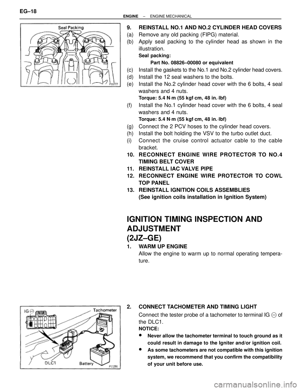
9. REINSTALL NO.1 AND NO.2 CYLINDER HEAD COVERS
(a) Remove any old packing (FIPG) material.
(b) Apply seal packing to the cylinder head as shown in the
illustration.
Seal packing:
Part No. 08826±00080 or equivalent
(c) Install the gaskets to the No.1 and No.2 cylinder head covers.
(d) Install the 12 seal washers to the bolts.
(e) Install the No.2 cylinder head cover with the 6 bolts, 4 seal
washers and 4 nuts.
Torque: 5.4 NVm (55 kgfVcm, 48 in.Vlbf)
(f) Install the No.1 cylinder head cover with the 6 bolts, 4 seal
washers and 4 nuts.
Torque: 5.4 NVm (55 kgfVcm, 48 in.Vlbf)
(g) Connect the 2 PCV hoses to the cylinder head covers.
(h) Install the bolt holding the VSV to the turbo outlet duct.
(i) Connect the cruise control actuator cable to the cable
bracket.
10. RECONNECT ENGINE WIRE PROTECTOR TO NO.4
TIMING BELT COVER
11. REINSTALL IAC VALVE PIPE
12. RECONNECT ENGINE WIRE PROTECTOR TO COWL
TOP PANEL
13. REINSTALL IGNITION COILS ASSEMBLIES
(See ignition coils installation in Ignition System)
IGNITION TIMING INSPECTION AND
ADJUSTMENT
(2JZ±GE)
1. WARM UP ENGINE
Allow the engine to warm up to normal operating tempera-
ture.
2. CONNECT TACHOMETER AND TIMING LIGHT
Connect the tester probe of a tachometer to terminal IG � of
the DLC1.
NOTICE:
wNever allow the tachometer terminal to touch ground as it
could result in damage to the Igniter and/or ignition coil.
wAs some tachometers are not compatible with this ignition
system, we recommend that you confirm the compatibility
of your unit before use.
EG±18± ENGINEENGINE MECHANICAL
Page 1333 of 2543
3. CHECK IDLE SPEED
(a) Race the engine speed at 2,500 rpm for approx. 90 seconds.
(b) Check the idle speed.
Idle speed:
700 + 50 rpm
4. ADJUST IGNITION TIMING
(a) Using SST, connect terminals TE1 and E1 of the DLC 1.
SST 09843±18020
(b) Using a timing light, check the ignition timing.
Ignition timing:
10 + 2° BTDC @ idle
(Transmission in neutral position)
(c) Loosen the nut, and adjust by turning the distributor.
Ignition timing:
10° BTDC @ idle
(Transmission in neutral position)
(d) Tighten the nut, and recheck the ignition timing.
Torque: 19 NVm (195 kgfVcm, 14 ftVlbf)
(e) Remove the SST from the DLC1.
SST 09843±18020
5. FURTHER CHECK IGNITION TIMING
Ignition timing:
7±19° BTDC @ idle
(Transmission in neutral position)
HINT: The timing mark moves in a range between 75 and 195.
6. DISCONNECT TACHOMETER AND TIMING LIGHT
± ENGINEENGINE MECHANICALEG±19
Page 1344 of 2543
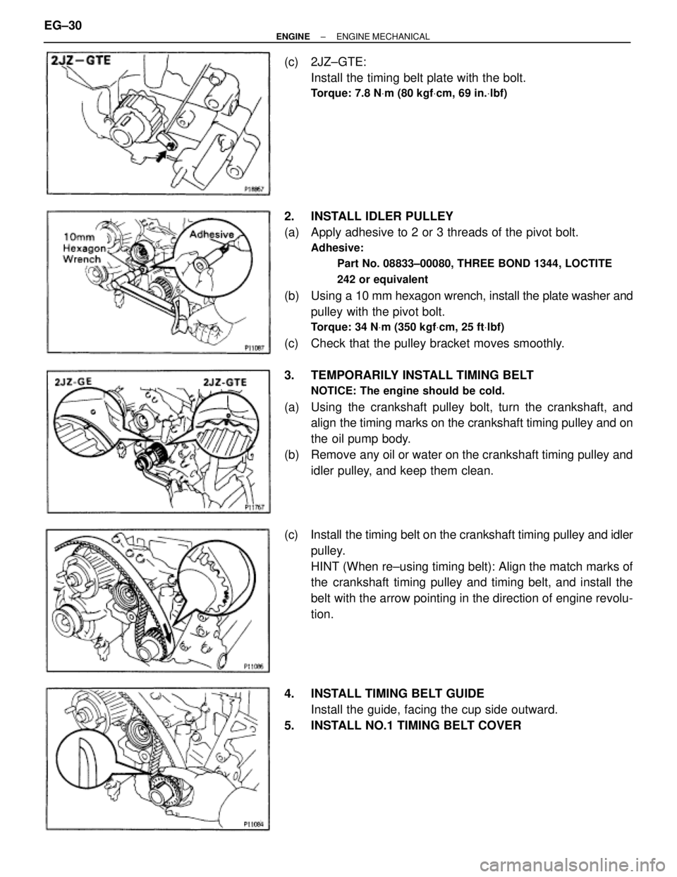
(c) 2JZ±GTE:
Install the timing belt plate with the bolt.
Torque: 7.8 NVm (80 kgfVcm, 69 in.Vlbf)
2. INSTALL IDLER PULLEY
(a) Apply adhesive to 2 or 3 threads of the pivot bolt.
Adhesive:
Part No. 08833±00080, THREE BOND 1344, LOCTITE
242 or equivalent
(b) Using a 10 mm hexagon wrench, install the plate washer and
pulley with the pivot bolt.
Torque: 34 NVm (350 kgfVcm, 25 ftVlbf)
(c) Check that the pulley bracket moves smoothly.
3. TEMPORARILY INSTALL TIMING BELT
NOTICE: The engine should be cold.
(a) Using the crankshaft pulley bolt, turn the crankshaft, and
align the timing marks on the crankshaft timing pulley and on
the oil pump body.
(b) Remove any oil or water on the crankshaft timing pulley and
idler pulley, and keep them clean.
(c) Install the timing belt on the crankshaft timing pulley and idler
pulley.
HINT (When re±using timing belt): Align the match marks of
the crankshaft timing pulley and timing belt, and install the
belt with the arrow pointing in the direction of engine revolu-
tion.
4. INSTALL TIMING BELT GUIDE
Install the guide, facing the cup side outward.
5. INSTALL NO.1 TIMING BELT COVER EG±30
± ENGINEENGINE MECHANICAL
Page 1345 of 2543
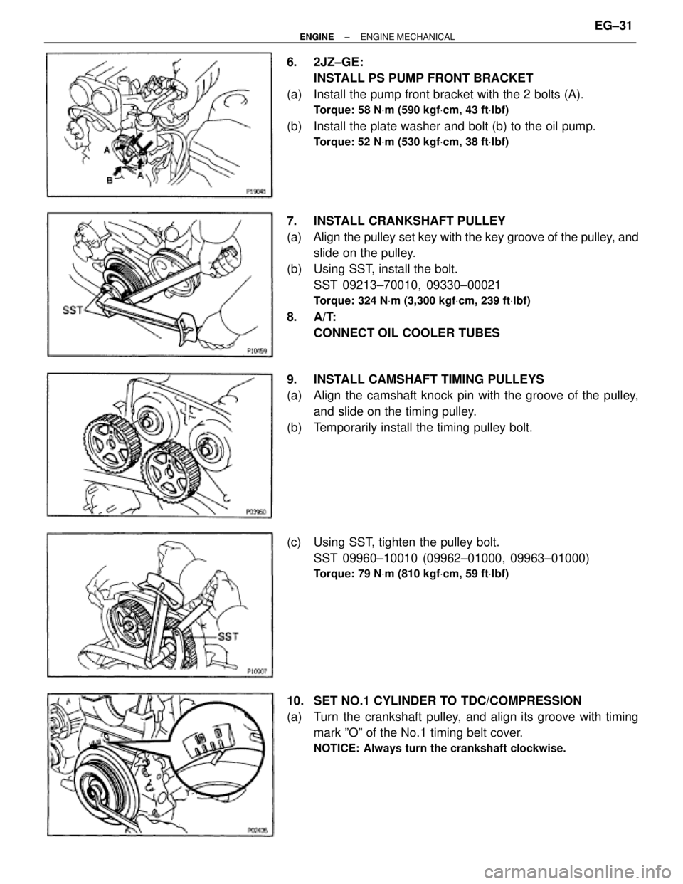
6. 2JZ±GE:
INSTALL PS PUMP FRONT BRACKET
(a) Install the pump front bracket with the 2 bolts (A).
Torque: 58 NVm (590 kgfVcm, 43 ftVlbf)
(b) Install the plate washer and bolt (b) to the oil pump.
Torque: 52 NVm (530 kgfVcm, 38 ftVlbf)
7. INSTALL CRANKSHAFT PULLEY
(a) Align the pulley set key with the key groove of the pulley, and
slide on the pulley.
(b) Using SST, install the bolt.
SST 09213±70010, 09330±00021
Torque: 324 NVm (3,300 kgfVcm, 239 ftVlbf)
8. A/T:
CONNECT OIL COOLER TUBES
9. INSTALL CAMSHAFT TIMING PULLEYS
(a) Align the camshaft knock pin with the groove of the pulley,
and slide on the timing pulley.
(b) Temporarily install the timing pulley bolt.
(c) Using SST, tighten the pulley bolt.
SST 09960±10010 (09962±01000, 09963±01000)
Torque: 79 NVm (810 kgfVcm, 59 ftVlbf)
10. SET NO.1 CYLINDER TO TDC/COMPRESSION
(a) Turn the crankshaft pulley, and align its groove with timing
mark ºOº of the No.1 timing belt cover.
NOTICE: Always turn the crankshaft clockwise.
± ENGINEENGINE MECHANICALEG±31
Page 1346 of 2543
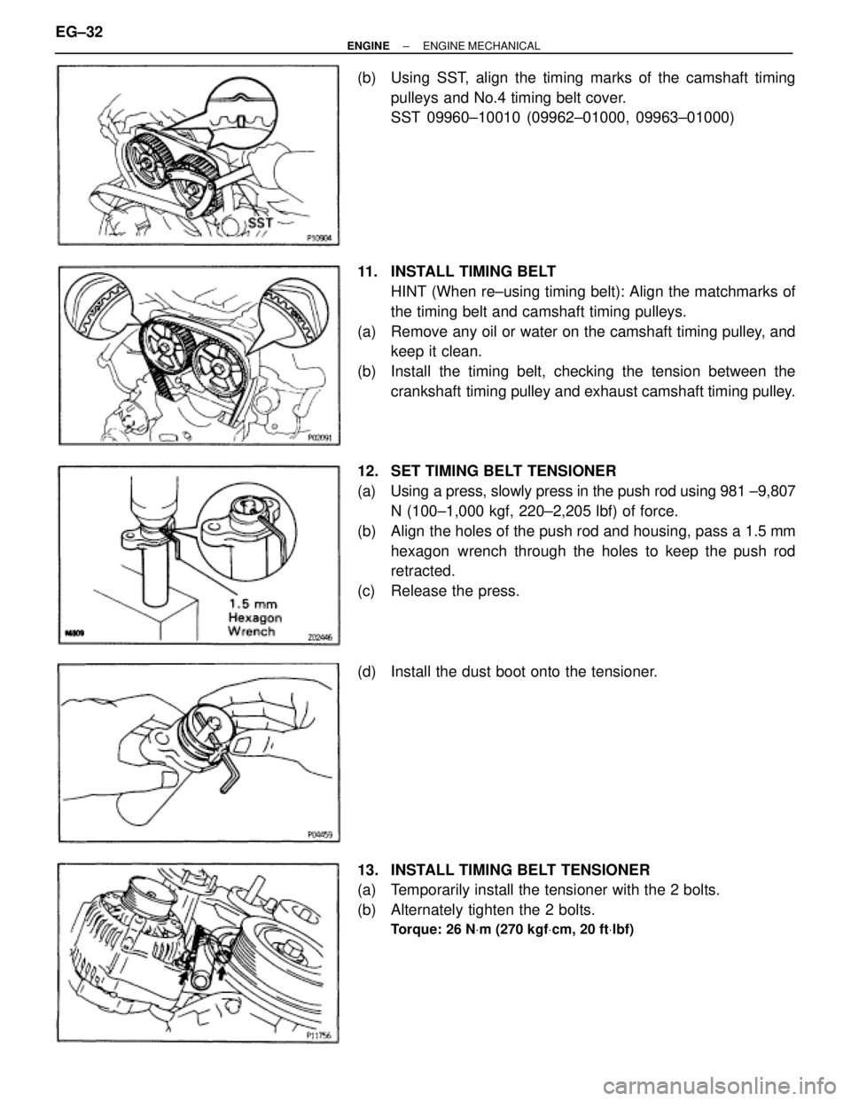
(b) Using SST, align the timing marks of the camshaft timing
pulleys and No.4 timing belt cover.
SST 09960±10010 (09962±01000, 09963±01000)
11. INSTALL TIMING BELT
HINT (When re±using timing belt): Align the matchmarks of
the timing belt and camshaft timing pulleys.
(a) Remove any oil or water on the camshaft timing pulley, and
keep it clean.
(b) Install the timing belt, checking the tension between the
crankshaft timing pulley and exhaust camshaft timing pulley.
12. SET TIMING BELT TENSIONER
(a) Using a press, slowly press in the push rod using 981 ±9,807
N (100±1,000 kgf, 220±2,205 lbf) of force.
(b) Align the holes of the push rod and housing, pass a 1.5 mm
hexagon wrench through the holes to keep the push rod
retracted.
(c) Release the press.
(d) Install the dust boot onto the tensioner.
13. INSTALL TIMING BELT TENSIONER
(a) Temporarily install the tensioner with the 2 bolts.
(b) Alternately tighten the 2 bolts.
Torque: 26 NVm (270 kgfVcm, 20 ftVlbf)
EG±32± ENGINEENGINE MECHANICAL
Page 1347 of 2543
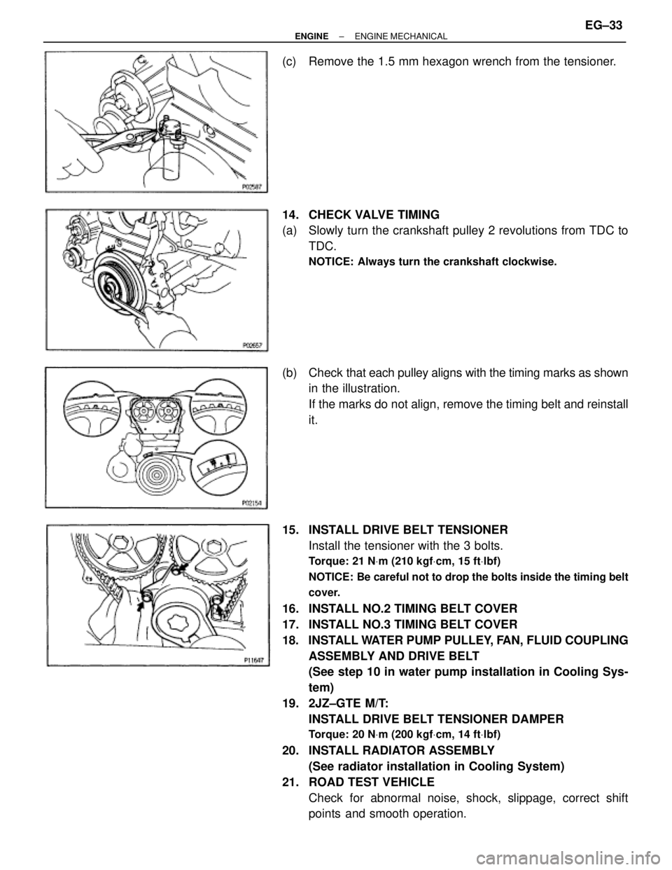
(c) Remove the 1.5 mm hexagon wrench from the tensioner.
14. CHECK VALVE TIMING
(a) Slowly turn the crankshaft pulley 2 revolutions from TDC to
TDC.
NOTICE: Always turn the crankshaft clockwise.
(b) Check that each pulley aligns with the timing marks as shown
in the illustration.
If the marks do not align, remove the timing belt and reinstall
it.
15. INSTALL DRIVE BELT TENSIONER
Install the tensioner with the 3 bolts.
Torque: 21 NVm (210 kgfVcm, 15 ftVlbf)
NOTICE: Be careful not to drop the bolts inside the timing belt
cover.
16. INSTALL NO.2 TIMING BELT COVER
17. INSTALL NO.3 TIMING BELT COVER
18. INSTALL WATER PUMP PULLEY, FAN, FLUID COUPLING
ASSEMBLY AND DRIVE BELT
(See step 10 in water pump installation in Cooling Sys-
tem)
19. 2JZ±GTE M/T:
INSTALL DRIVE BELT TENSIONER DAMPER
Torque: 20 NVm (200 kgfVcm, 14 ftVlbf)
20. INSTALL RADIATOR ASSEMBLY
(See radiator installation in Cooling System)
21. ROAD TEST VEHICLE
Check for abnormal noise, shock, slippage, correct shift
points and smooth operation.
± ENGINEENGINE MECHANICALEG±33
Page 1372 of 2543
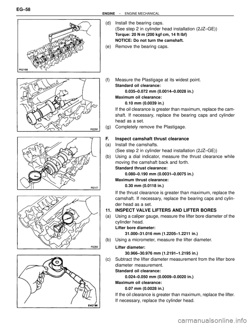
(d) Install the bearing caps.
(See step 2 in cylinder head installation (2JZ±GE))
Torque: 20 NVm (200 kgfVcm, 14 ftVlbf)
NOTICE: Do not turn the camshaft.
(e) Remove the bearing caps.
(f) Measure the Plastigage at its widest point.
Standard oil clearance:
0.035±0.072 mm (0.0014±0.0028 in.)
Maximum oil clearance:
0.10 mm (0.0039 in.)
If the oil clearance is greater than maximum, replace the cam-
shaft. If necessary, replace the bearing caps and cylinder
head as a set.
(g) Completely remove the Plastigage.
F. Inspect camshaft thrust clearance
(a) Install the camshafts.
(See step 2 in cylinder head installation (2JZ±GE))
(b) Using a dial indicator, measure the thrust clearance while
moving the camshaft back and forth.
Standard thrust clearance:
0.080±0.190 mm (0.0031±0.0075 in.)
Maximum thrust clearance:
0.30 mm (0.0118 in.)
If the thrust clearance is greater than maximum, replace the
camshaft. If necessary, replace the bearing caps and cylin-
der head as a set.
11. INSPECT VALVE LIFTERS AND LIFTER BORES
(a) Using a caliper gauge, measure the lifter bore diameter of the
cylinder head.
Lifter bore diameter:
31.000±31.016 mm (1.2205±1.2211 in.)
(b) Using a micrometer, measure the lifter diameter.
Lifter diameter:
30.966±30.976 mm (1.2191±1.2195 in.)
(c) Subtract the lifter diameter measurement from the lifter bore
diameter measurement.
Standard oil clearance:
0.024±0.050 mm (0.0009±0.0020 in.)
Maximum oil clearance:
0.07 mm (0.0028 in.)
If the oil clearance is greater than maximum, replace the lifter.
If necessary, replace the cylinder head. EG±58
± ENGINEENGINE MECHANICAL
Page 1375 of 2543
(b) Install these parts:
(1) Valve
(2) Spring seat
(3) Valve spring
(4) Spring retainer
HINT: Install the valve spring, facing the painted mark up-
ward.
(c) Using SST, compress the valve spring and place the 2
keepers around the valve stem.
SST 09202±70010
(d) Using a plastic±faced hammer, lightly tap the valve stem tip
to ensure a proper fit.
3. INSTALL VALVE LIFTERS AND SHIMS
(a) Install the valve lifter and shim.
(b) Check that the valve lifter rotates smoothly by hand.
4. INSTALL EGR COOLER
Install a new gasket and the EGR cooler with the 8 bolts.
Torque: 8.8 NVm (90 kgfVcm, 78 in.Vlbf)
5. 2JZ±GE:
INSTALL ECT SENSOR AND SENDER GAUGE
Torque: 20 NVm (200 kgfVcm, 14 ftVlbf)
6. 2JZ±GE:
INSTALL GROUND STRAP AND THROTTLE CABLE
BRACKET
7. 2JZ±GE:
INSTALL ENGINE HANGERS
Torque: 39 NVm (400 kgfVcm, 29 ftVlbf)
± ENGINEENGINE MECHANICALEG±61