1993 DODGE TRUCK oil filter
[x] Cancel search: oil filterPage 940 of 1502
•
FUEL
SYSTEM
14 - 121
Fig.
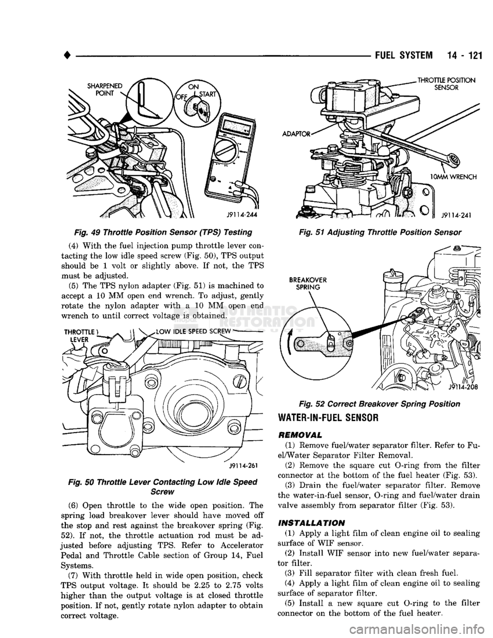
49
Throttle
Position
Sensor
(TPS) Testing (4) With the fuel injection pump throttle lever con
tacting the low idle speed screw (Fig. 50), TPS output should be 1 volt or slightly above. If not, the TPS
must be adjusted.
(5) The TPS nylon adapter (Fig. 51) is machined to
accept a 10 MM open end wrench. To adjust, gently
rotate the nylon adapter with a 10 MM open end
wrench to until correct voltage is obtained.
J9114-261
Fig.
50
Throttle
Lever
Contacting Low Idle
Speed Screw
(6)
Open throttle to the wide open position. The
spring load breakover lever should have moved off
the stop and rest against the breakover spring (Fig.
52).
If not, the throttle actuation rod must be ad
justed before adjusting TPS. Refer to Accelerator Pedal and Throttle Cable section of Group 14, Fuel Systems.
(7) With throttle held in wide open position, check
TPS output voltage. It should be 2.25 to 2.75 volts
higher than the output voltage is at closed throttle position. If not, gently rotate nylon adapter to obtain
correct voltage.
Fig.
51 Adjusting
Throttle
Position
Sensor
Fig.
52 Correct Breakover
Spring
Position
WATER-IN-FUEL
SENSOR
REMOVAL
(1) Remove fuel/water separator filter. Refer to Fu
el/Water Separator Filter Removal.
(2) Remove the square cut O-ring from the filter
connector at the bottom of the fuel heater (Fig. 53). (3) Drain the fuel/water separator filter. Remove
the water-in-fuel sensor, O-ring and fuel/water drain
valve assembly from separator filter (Fig. 53).
INSTALLATION
(1) Apply a light film of clean engine oil to sealing
surface of WIF sensor. (2) Install WIF sensor into new fuel/water separa
tor filter.
(3) Fill separator filter with clean fresh fuel.
(4) Apply a light film of clean engine oil to sealing
surface of separator filter.
(5) Install a new square cut O-ring to the filter
connector on the bottom of the fuel heater.
Page 1091 of 1502
21 - 90
AUTOMATIC
TRANSMISSION—32RH/36RH/37RH/42RH/46RH
• (4) Note pressure with engine at curb idle speed
and rear wheels stopped. Pressure should be zero to 1-1/2 psi maximum. If pressure exceeds this figure,
governor valve or weights are sticking open.
(5) Slowly increase engine rpm and observe speed
ometer and pressure test gauge. Governor pressure should increase in proportion to indicated vehicle
speed (or approximately 1 psi for every 1 mph).
(6) Pressure rise should be smooth and drop back
to 0 to 1-1/2 psi when wheels are braked to a stop and engine returns to curb idle speed.
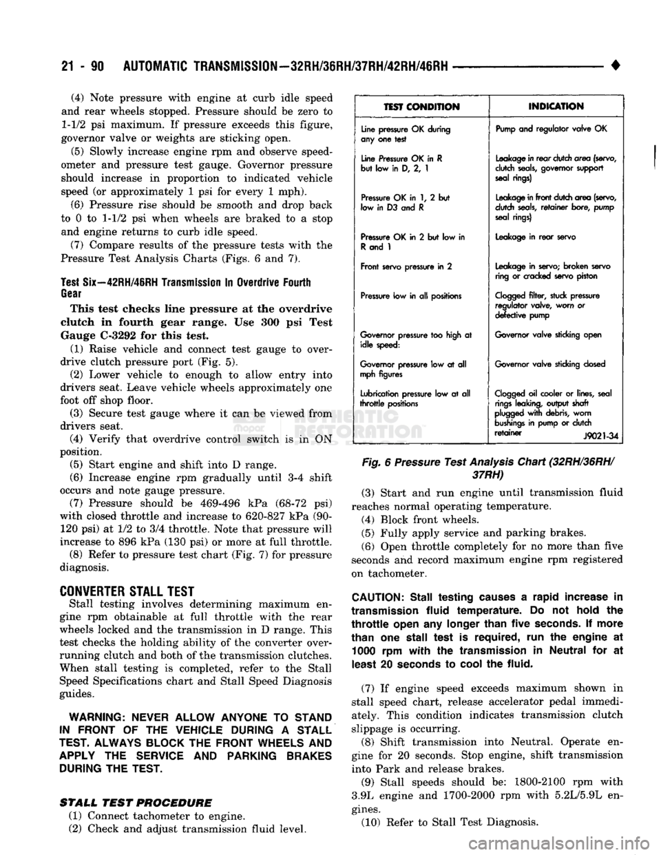
(7) Compare results of the pressure tests with the
Pressure Test Analysis Charts (Figs. 6 and 7).
Test
Six—42RH/46RH
Transmission
In Overdrive Fourth
Gear
This test checks line pressure at the overdrive
clutch in fourth gear range. Use 300 psi Test
Gauge C-3292 for this test.
(1) Raise vehicle and connect test gauge to over
drive clutch pressure port (Fig. 5). (2) Lower vehicle to enough to allow entry into
drivers seat. Leave vehicle wheels approximately one
foot off shop floor.
(3) Secure test gauge where it can be viewed from
drivers seat.
(4) Verify that overdrive control switch is in ON
position. (5) Start engine and shift into D range.
(6) Increase engine rpm gradually until 3-4 shift
occurs and note gauge pressure. (7) Pressure should be 469-496 kPa (68-72 psi)
with closed throttle and increase to 620-827 kPa (90- 120 psi) at 1/2 to 3/4 throttle. Note that pressure will
increase to 896 kPa (130 psi) or more at full throttle. (8) Refer to pressure test chart (Fig. 7) for pressure
diagnosis.
CONVERTER
STALL
TEST
Stall testing involves determining maximum en
gine rpm obtainable at full throttle with the rear
wheels locked and the transmission in D range. This
test checks the holding ability of the converter over
running clutch and both of the transmission clutches. When stall testing is completed, refer to the Stall
Speed Specifications chart and Stall Speed Diagnosis
guides.
WARNING:
NEVER
ALLOW
ANYONE
TO
STAND
IN
FRONT
OF THE
VEHICLE
DURING
A
STALL
TEST.
ALWAYS
BLOCK
THE
FRONT
WHEELS
AND
APPLY
THE
SERVICE
AND
PARKING
BRAKES
DURING
THE
TEST.
STALL
TEST
PROCEDURE
(1) Connect tachometer to engine.
(2) Check and adjust transmission fluid level.
1EST
CONDITION
INDICATION
Line
pressure
OK during
any
one test
Pump
and regulator valve OK
Line
Pressure
OK in R
but low in D, 2, 1
Leakage
in
rear
dutch area
(servo,
dutch
seals,
governor
support
seal
rings)
Pressure
OK in 1, 2 but
low
in D3 and R
Leakage
in
front
dutch area
(servo,
dutch
seals,
retainer
bore,
pump
seal
rings)
Pressure
OK in 2 but low in
R
and 1
Leakage
in
rear
servo
Front
servo
pressure
in 2
Leakage
in
servo;
broken
servo
ring
or
cracked
servo
piston
Pressure
low in all
positions
Cogged
filter,
stuck
pressure
regulator valve, worn or
defective
pump
Governor
pressure
too
high
at idle
speed:
Governor
valve
sticking
open
Governor
pressure
low at all
mph
figures
Governor
valve
sticking
dosed
Lubrication
pressure
low at all
throttle
positions
Clogged
oil cooler or
lines,
seal
rings
leaking,
output shaft
plugged
with
debris,
worn
bushings
in
pump
or dutch
retainer
J9021-34
Fig.
6
Pressure
Test
Analysis
Chart (32RH/36RH/
37RH)
(3) Start and run engine until transmission fluid
reaches normal operating temperature. (4) Block front wheels.
(5) Fully apply service and parking brakes.
(6) Open throttle completely for no more than five
seconds and record maximum engine rpm registered
on tachometer.
CAUTION:
Stall testing
causes
a rapid increase in
transmission
fluid
temperature. Do not
hold
the
throttle
open
any
longer
than
five
seconds.
If more
than one stall test is required, run the engine at 1000 rpm
with
the
transmission
in Neutral for at
least
20
seconds
to
cool
the fluid.
(7) If engine speed exceeds maximum shown in
stall speed chart, release accelerator pedal immedi
ately. This condition indicates transmission clutch
slippage is occurring.
(8) Shift transmission into Neutral. Operate en
gine for 20 seconds. Stop engine, shift transmission
into Park and release brakes.
(9) Stall speeds should be: 1800-2100 rpm with
3.9L engine and 1700-2000 rpm with 5.2L/5.9L en
gines.
(10) Refer to Stall Test Diagnosis.
Page 1092 of 1502
AUTOMATIC
TRANSMISSION—32RH/36RH/37RH/42RH/46RH
21 - 91
TEST
CONDITION
Line pressure OK during
any one test
Line Pressure OK in
R
but low in D, 2, 1
Pressure Low in D
Fourth Gear Range
Pressure OK in 1, 2 but
low
in
D3
and
R
Pressure OK in 2 but low in
R
and 1
Front servo pressure low
in 2
Pressure low in all positions
Governor pressure too high
at idle speed
Governor pressure low
at all mph figures Lubrication pressure low at
all throttle positions
INDICATION
Pump and regulator valve OK
Leakage in rear clutch area (servo,
clutch seals, governor support seal rings)
Overdrive clutch piston seal, or
check ball problem
Leakage in front clutch area (servo,
clutch seals, retainer bore, pump seal rings)
Leakage in rear servo
Leakage in servo; broken servo
ring or cracked servo piston
Clogged filter, stuck regulator
valve, worn or faulty pump, plugged fluid cooler
Governor valve sticking open
Governor valve sticking closed
Clogged oil cooler or lines, seal rings leaking, output shaft plugged
with debris, worn bushings in pump or clutch retainer
J9321-165
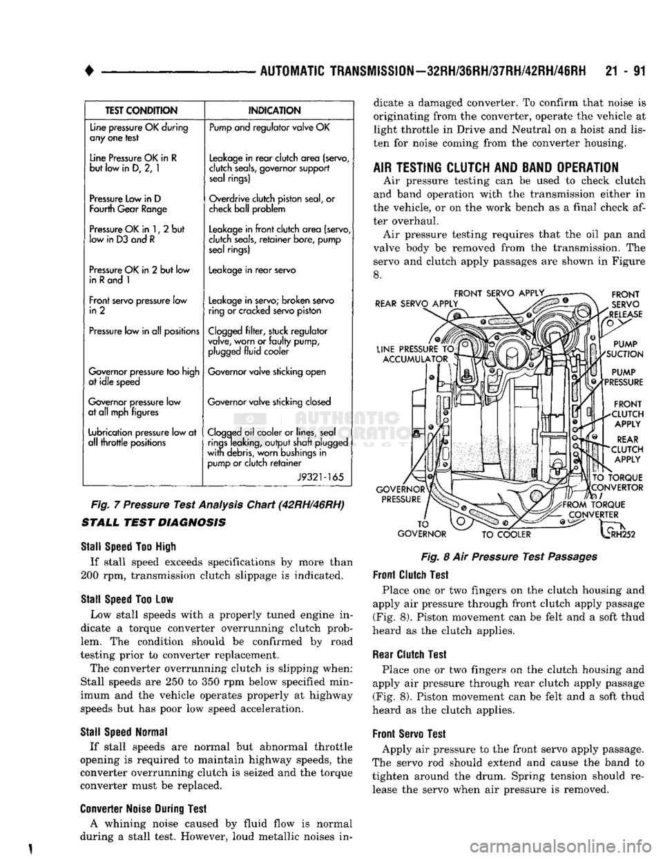
Fig.
7
Pressure
Test
Analysis
Chart (42RH/46RH)
STALL
TEST
DIAGNOSIS
Stall
Speed
Too
High
If stall speed exceeds specifications by more than
200 rpm, transmission clutch slippage is indicated.
Stall
Speed
Too Low Low stall speeds with a properly tuned engine in
dicate a torque converter overrunning clutch prob
lem. The condition should be confirmed by road
testing prior to converter replacement. The converter overrunning clutch is slipping when:
Stall speeds are 250 to 350 rpm below specified min
imum and the vehicle operates properly at highway
speeds but has poor low speed acceleration.
Stall
Speed
Normal
If stall speeds are normal but abnormal throttle
opening is required to maintain highway speeds, the
converter overrunning clutch is seized and the torque
converter must be replaced.
Converter
Noise
During
Test
A whining noise caused by fluid flow is normal
during a stall test. However, loud metallic noises in dicate a damaged converter. To confirm that noise is
originating from the converter, operate the vehicle at
light throttle in Drive and Neutral on a hoist and
lis
ten for noise coming from the converter housing.
AIR
TESTING
CLUTCH
AND
BAND
OPERATION
Air pressure testing can be used to check clutch
and band operation with the transmission either in
the vehicle, or on the work bench as a final check af
ter overhaul. Air pressure testing requires that the oil pan and
valve body be removed from the transmission. The servo and clutch apply passages are shown in Figure
8.
FRONT
SERVO
APPLY^
REAR
SERVO
APPLY
LINE
PRESSURE
TO
ACCUMULATOR
GOVERNOR
PRESSURE
FRONT
SERVO
RELEASE
PUMP
SUCTION
PUMP
PRESSURE
FRONT
CLUTCH
APPLY
REAR
CLUTCH
APPLY
TO
TORQUE
CONVERTOR
I
FROM
TORQUE
CONVERTER
TO
GOVERNOR
TO
COOLER
^H252
Fig.
8 Air
Pressure
Test
Passages
Front
Clutch
Test
Place one or two fingers on the clutch housing and
apply air pressure through front clutch apply passage (Fig. 8). Piston movement can be felt and a soft thud
heard as the clutch applies.
Rear
Clutch
Test
Place one or two fingers on the clutch housing and
apply air pressure through rear clutch apply passage
(Fig. 8). Piston movement can be felt and a soft thud
heard as the clutch applies.
Front
Servo
Test
Apply air pressure to the front servo apply passage.
The servo rod should extend and cause the band to
tighten around the drum. Spring tension should re lease the servo when air pressure is removed.
Page 1097 of 1502
21 - 96
AUTOMATIC
TRANSMISSION—32RH/36RH/37RH/42RH/46RH
• Condition
Possible
Cause
Correction
HARSH
ENGAGEMENT
(FROM
NEUTRAL
TO
DRIVE
OR
REVERSE)
Note: The shift from
neutral
to
reverse is normally
quite
firm. Hydraulic pressure at the
rear
servo can approach 300 psi in
reverse gear. Do not confuse a
firm
engagement
with
a
truly
harsh engagement
1.
Engine
idle
speed too high
2. Driver "riding" accelerator pedal during shift
3.
Throttle
cable or linkage misadjusted
4. Band adjustment needed
5.
Loose
mounting bolts
6 Worn or damaged
U-joints
7.
Loose
axle
pinion nut
8. Hydraulic pressure is incorrect
9. Accumulator piston spring, or seal worn or damaged
10. Faulty converter clutch (if equipped)
11.
Clutch, band, or
planetary
component
is
damaged 1. Check/adjust
idle
speed
2. Advise owner/operator
3. Adjust cable or linkage; setting is
either
too long or too short
4. Adjust
front/rear
bands
5. Check engine, transmission,
propeller
shaft, crossmember, and
axle
bolt torque;
tighten
loose
bolts and replace
missing
bolts
6. Remove
propeller
shaft and replace
U-joints
7. Replace nut and check pinion threads
before
installing new nut; replace pinion gear if
threads are damaged
8. Check pressures; remove, overhaul, or adjust valve body as needed;
repair
oil pump if
necessary
9. Remove valve body and replace piston,
seal,
or spring as needed
10. Replace converter and flush cooler and lines
before
installing new converter
11.
Remove, disassemble, and
repair
transmission
as necessary
DELAYED
ENGAGEMENT
(FROM
NEUTRAL
TO
DRIVE
OR
REVERSE)
1.
Engine
idle
speed too low
2. Low
fluid
level
3. Gearshift linkage but of adjustment
4. Rear band out of adjustment
5.
Valve body
filter
plugged
6. Oil pump gears worn or damaged or pump body or seal is damaged, allowing pump to
take
in air, causing
fluid
aeration
7. Reaction shaft seal rings worn or broken
8. Governor valve stuck or valve shaft is loose or damaged
9. Low hydraulic pressure
10. Clutch, band, or servo damage
1.
Adjust
idle
speed
2. Correct
level
and check for leaks
3. Adjust cable or linkage and
repair
linkage if worn or damaged
4. Adjust band
5. Replace
fluid
and
filter.
If oil pan and old
fluid
were
full
of clutch
disc
material
and/or
metal
particles, overhaul
will
be necessary
6. Remove transmission and replace oil pump
7. Remove transmission, remove oil pump, and replace seal rings
8. Remove and inspect governor components; replace worn or damaged parts
9. Perform pressure test, remove transmission, and
repair
as needed
10. Remove and disassemble transmission and
repair
as necessary
J9321-255
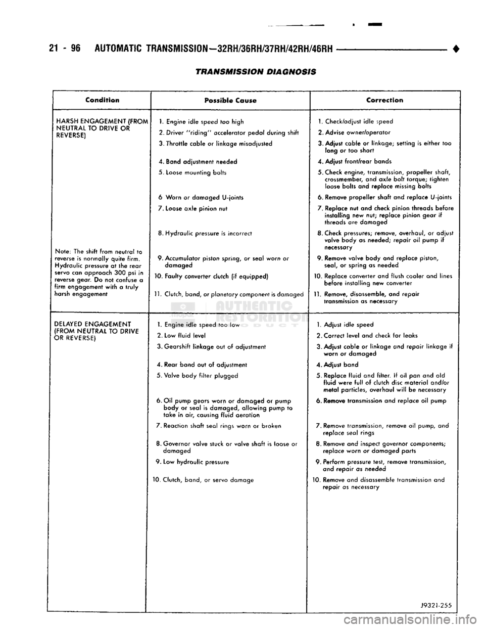
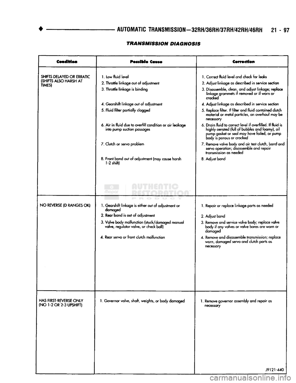
TRANSMISSION DIAGNOSIS
Page 1098 of 1502
•
AUTOMATIC
TRANSMISSION—32RH/36RH/37RH/42RH/46RH
21 - 97
Cenoltfeie
Possible
Caws®
Cowscilon
SHIFTS
DELAYED
OR
ERRATIC
(SHIFTS
ALSO
HARSH
AT
TIMES)
1.
Low
fluid
level
2.
Throttle
linkage out
of
adjustment
3.
Throttle
linkage
is
binding
4.
Gearshift linkage out
of
adjustment
5. Fluid
filter
partially
clogged
6. Air in
fluid
due to
overfill
condition or
air
leakage
into
pump suction
passages
7.
Clutch
or
servo problem
8. Front band out of adjustment (may
cause
harsh
1-2
shift)
1.
Correct
fluid
level
and check
for
leaks
2. Adjust linkage
as
described in service section
3.
Disassemble,
clean, and adjust linkage; replace linkage grommets
if
removed
or if
worn or
cracked
4.
Adjust linkage
as
described in service section
5. Replace
filter. If filter
and
fluid
contained clutch
material
or
metal
particles, an overhaul may
be
necessary
6. Drain
fluid
to correct
level
if
overfilled.
If
fluid
is
highly
aerated
(full
of
bubbles
and foamy),
oil
pump
gasket
or seal may have failed,
or
pump
body
is
porous
or cracked
7.
Remove valve body and
air
test clutch, band and
servo
operation;
disassemble
and
repair
transmission
as needed
8. Adjust band
NO
REVERSE
(D
RANGES
OK)
1.
Gearshift linkage is
either
out of adjustment or
damaged
2. Rear band
is
out
of
adjustment
3. Valve body malfunction (stuck/damaged manual valve, regulator valve,
or
check ball)
4.
Rear servo or
front
clutch malfunction
1.
Repair or replace linkage parts as needed
2. Adjust band
3. Remove and service valve body; replace valve body
if
any valves or valve bores are worn
or
damaged
4.
Remove and
disassemble
transmission;
replace worn, damaged servo and clutch parts as
necessary
HAS
FIRST-REVERSE
ONLY
(NO
1-2
OR
2-3
UPSHIFT)
1.
Governor valve, shaft, weights, or body damaged
1.
Remove governor
assembly
and
repair
as
necessary
J9121-440
TRANSMISSION DIAGNOSIS
Page 1103 of 1502
21-102
AUTOMATIC
TRANSMISSION—32RH/36RH/37RH/42RH/46RH
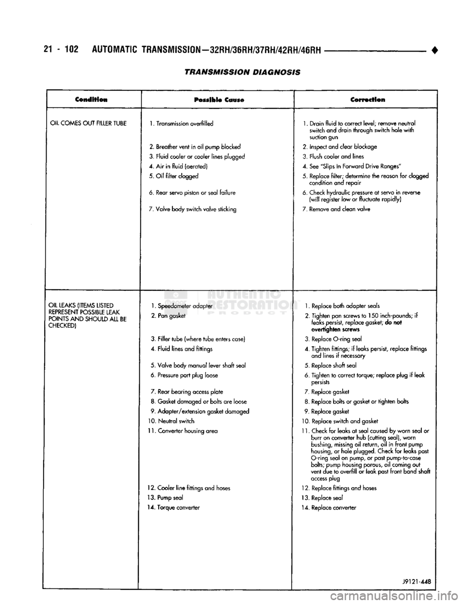
TRANSMISSION
DIAGNOSIS
•
Condition
Possible
Cause Correction
OIL
COMES
OUT
FILLER
TUBE
1.
Transmission
overfilled
1.
Drain
fluid
to
correct
level;
remove
neutral
switch
and drain
through
switch
hole
with
suction
gun
2.
Breather
vent
in
oil
pump
blocked
2.
Inspect
and
clear
blockage
3,
Fly id
cooler
or cooler
lines
plugged
3.
Flush
cooler and lines
4. Air in
fluid
(aerated)
4.
See
"Slips
In
Forward
Drive
Ranges"
5.
Oil
filter
clogged
5.
Replace
filter;
determine
the reason for clogged
condition and
repair
6.
tear
servo
piston
or
seal
failure
6.
Check hydraulic pressure at servo
in
reverse
(will
register
low or
fluctuate
rapidly)
7.
Valve body
switch
valve
sticking
7.
Remove
and
clean
valve
OIL
LEAKS
(ITEMS
LISTED
REPRESENT
POSSIBLE
LEAK
POINTS
AND
SHOULD
ALL
BE
CHECKED)
1.
Speedometer
adapter
2.
Pan
gasket
3.
Filler
tube
(where
tube
enters
case)
4.
Fluid
lines
and
fittings
5.
Valve body
manual
lever
shaft
seal
6.
Pressure
port
plug
loose 7. Rear
bearing
access
plate
8. Gasket damaged or
bolts
are loose
9.
Adapter/extension
gasket damaged
10.
Neutral
switch
11.
Converter
housing area
12. Cooler
line
fittings and hoses
13. Pump seal
14. Torque converter
1.
Replace both adapter seals
2. Tighten pan screws to 150 inch-pounds; if
leaks
persist,
replace
gasket;
do not
overtighten screws
3. Replace O-ring seal
4. Tighten fittings; if leaks persist, replace fittings and lines if necessary
5. Replace shaft seal
6. Tighten to correct torque; replace plug if leak
persists
7. Replace gasket
8. Replace bolts or gasket or tighten bolts
9. Replace gasket
10. Replace switch and gasket
11. Check for leaks at seal caused by worn seal or burr on converter hub (cutting seal), worn
bushing,
missing
oil
return,
oil in
front
pump
housing,
or hole plugged. Check for leaks past
O-ring seal on pump, or past pump-to-case
bolts;
pump housing porous, oil coming out
vent due to
overfill
or leak past
front
band shaft
access
plug
12. Replace fittings and hoses
13. Replace seal 14. Replace converter
J9121-448
Page 1104 of 1502
•
AUTOMATIC
TRANSMISSION—32RH/36RH/37RH/42RH/46RH
21-103
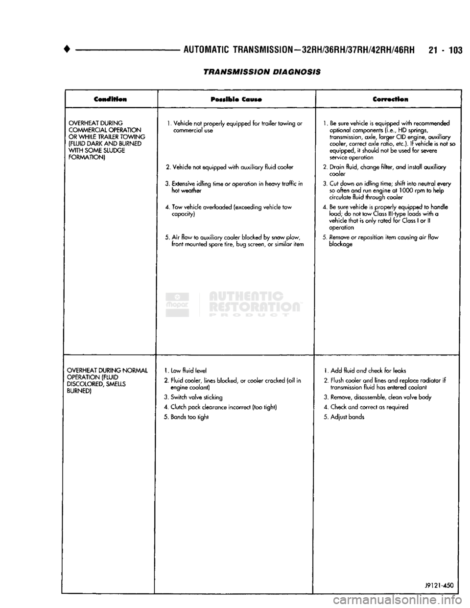
TRANSMISSION DIAGNOSIS
Condition
Possible
Couso
Correction
OVERHEAT
DURING
COMMERCIAL
OPERATION
OR
WHILE
TRAILER
TOWING
(FLUID
DARK
AND
BURNED
WITH
SOME
SLUDGE
FORMATION)
1.
Vehicle not properly equipped for
trailer
towing or
commercial use
2. Vehicle not equipped
with
auxiliary fluid cooler
3.
Extensive idling
time
or operation in heavy
traffic
in hot weather
4. Tow vehicle overloaded (exceeding vehicle tow capacity)
5. Air flow to auxiliary cooler blocked by snow plow,
front
mounted spare
tire,
bug screen, or similar
item
1.
Be sure vehicle is equipped
with
recommended
optional components
(i.e.,
HD
springs,
transmission,
axle, larger CID engine, auxiliary cooler, correct axle ratio, etc.). If vehicle is not so
equipped, it should not be used for severe
service operation
2. Drain fluid, change
filter,
and install auxiliary cooler
3.
Cut down on idling time; shift into
neutral
every
so
often and run engine at 1000 rpm to help
circulate fluid through cooler
4. Be sure vehicle is properly equipped to handle
load;
do not tow
Class
Ill-type loads
with
a
vehicle
that
is only
rated
for
Class
1
or II operation
5.
Remove or reposition
item
causing
air flow
blockage
OVERHEAT
DURING
NORMAL
OPERATION
(FLUID
DISCOLORED,
SMELLS
BURNED)
1.
Low
fluid
level
2. Fluid cooler, lines blocked, or cooler cracked (oil in engine coolant)
3.
Switch valve sticking
4. Clutch pack clearance incorrect (too tight)
5.
Bands
too tight 1. Add
fluid
and check for leaks
2. Flush cooler and lines and replace radiator if
transmission
fluid has
entered
coolant
3.
Remove,
disassemble,
clean valve body
4. Check and correct as required
5. Adjust bands
J9121-450
Page 1114 of 1502
GOVERNOR VALVE
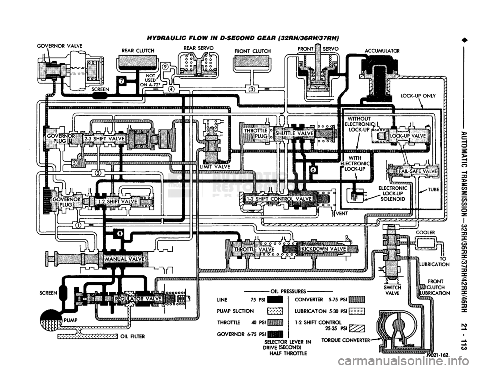
HYDRAULIC FLOW IN DSEGOND GEAR (32RH/36RH/37RH)
FRONT
M
SERVO REAR SERVO
FRONT
CLUTCH
ACCUMULATOR
3 OIL
FILTER
LINE
75
PSI
PUMP
SUCTION
\y>>>
THROTTLE
40
PSI
WMM
GOVERNOR
6-75 PSI
CONVERTER
5-75
PSI
LUBRICATION
5-30
PSI
WMM (j
1-2
SHIFT CONTROL
M
25-35
PSI
^ (i
SELECTOR
LEVER
IN
TORQUE CONVERTER-**!
DRIVE
(SECOND)
(|
HALF THROTTLE TO
LUBRICATION
FRONT
^CLUTCH
LUBRICATION
J9021-162