1993 DODGE TRUCK oil filter
[x] Cancel search: oil filterPage 611 of 1502

9
- 6
ENGINES
•
SERVICE DIAGNOSIS (GASOLINE ENGINES)
•
PERFORMANCE (CONT.)
1
CONDITION
POSSIBLE
CAUSES
^
CORRECTION
1
ENGINE
LOSS
OF
POWER
1.
Incorrect ignition timing.
2. Worn or burned distributor
rotor.
3. Worn distributor shaft.
4.
Dirty
or
incorrectly
gapped
spark
plugs.
5.
Dirt
or
water
in
fuel
system.
6.
Faulty
fuel
pump.
7.
Incorrect valve timing.
8.
Blown
cylinder head
gasket.
9.
Low
compression.
10.
Burned,
warped or
pitted
valves.
11.
Plugged
or
restricted
exhaust
system.
12. Faulty ignition
cables.
13. Faulty coil.
1.
Refer
to
Group
8D, Ignition
System.
2. install new distributor
rotor.
3.
Remove
and
repair
distributor
(refer
to
Group
8D, Ignition
System).
4.
Clean
plugs
and
set gap
(refer
to
Group
8D, Ignition
System).
5. Clean
system
and replace
fuel
filter.
6. Install new
fuel
pump.
7.
Correct
valve
timing.
8. Install new cylinder head
gasket.
9.
Test
compression
of
each
cylinder.
10.
Install new
valves.
11.
Install new
parts,
as
necessary.
12.
Replace
any cracked or
shorted
cables.
13.
Test
and
replace,
as
necessary
(refer
to
Group
8D, Ignition
System).
ENGINE
MISSES
ON
ACCELERATION
1.
Dirty
or
gap set
too
wide
in spark
plug.
2. Incorrect ignition timing.
3.
Dirt
in
fuel
system.
4.
Burned,
warped or
pitted
valves.
5. Faulty coil.
1.
Clean spark
plugs
and set gap
(refer
to
Group
8D, Ignition
System).
2. Refer to
Group
8D, Ignition
System.
3. Clean
fuel
system.
4.
Install new
valves.
5.
Test
and
replace,
if
necessary,
(refer
to
Group
8D, Ignition
System).
ENGINE
MISSES
AT HIGH
SPEED
1.
Dirty
or
gap set too
wide
in spark
plug.
2. Worn distributor shaft.
3. Worn or burned distributor
rotor.
4. Faulty
coil.
5. Incorrect ignition timing.
6.
Dirty
injector
in
throttle
body.
7.
Dirt
or
water
in
fuel
system.
1.
Clean
spark
plugs
and
set gap
(refer
to
Group
8D, Ignition
System).
2.
Remove
and
repair
distributor
(refer
to
Group
8D,
Ignition
System).
3. Install new distributor
rotor.
4.
Test
and replace,
as
necessary
(refer
to
Group
8D, Ignition
System).
5.
Refer
to
Group
8D, Ignition
System.
6.
Clean
injector.
7.
Clean
system
and replace
fuel
filter.
J9309-106
Page 612 of 1502
•
ENGINES
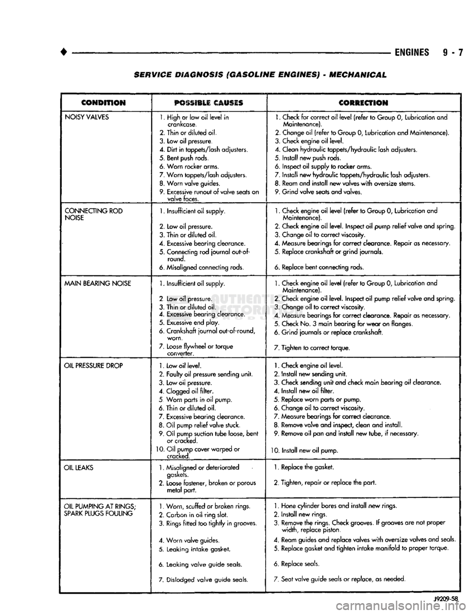
9 - 7 SERVICE DIAGNOSIS (GASOLINE ENGINES) - MECHANICAL
CONDITION
PSSSI1LI
CAUSIS
CORRECTION
NOISY
VALVES
1. High
or
low oil
level
in
crankcase.
2. Thin or
diluted
oil.
3.
Low
oil
pressure.
4.
Dirt
in
tappets/lash
adjusters.
5. Bent
push
rods.
6. Worn rocker arms.
7.
Worn
tappets/lash
adjusters.
8.
Worn
valve
guides.
9.
Excessive
runout
of
valve
seats
on
valve
faces.
1.
Check
for
correct oil
level
(refer
to
Group
0,
Lubrication and
Maintenance).
2. Change oil
(refer
to Group
0,
Lubrication and Maintenance).
3. Check engine oil level.
4. Clean hydraulic tappets/hydraulic lash adjusters.
5. Install new
push
rods.
6. Inspect oil supply to rocker arms.
7. Install new hydraulic tappets/hydraulic lash adjusters. 8. Ream and install new valves
with
oversize stems.
9. Grind valve seats and valves.
CONNECTING
ROD
NOISE
1.
Insufficient oil supply.
2.
Low oil
pressure.
3.
Thin
or
diluted
oil.
4.
Excessive
bearing
clearance.
5. Connecting rod
journal
out-of- round.
6. Misaligned connecting rods.
1.
Check engine oil
level
(refer
to Group
0,
Lubrication and
Maintenance).
2. Check engine oil level. Inspect oil pump
relief
valve and spring.
3. Change oil to correct
viscosity.
4. Measure bearings for correct clearance. Repair as necessary, 5. Replace crankshaft or grind journals.
6.
Replace
bent
connecting rods.
MAIN
BEARING
NOISE
1.
Insufficient oil supply.
2 Low
oil
pressure.
3. Thin or
diluted
oil.
4.
Excessive
bearing clearance. 5.
Excessive
end play.
6. Crankshaft
journal
out-of-round, worn,
7.
Loose
flywheel
or
torque
converter.
1.
Check engine oil
level
(refer
to Group
0,
Lubrication and
Maintenance).
2. Check engine oil level. Inspect oil pump
relief
valve and spring.
3. Change oil to correct
viscosity.
4. Measure bearings for correct clearance. Repair as necessary. 5. Check No.
3
main bearing for
wear
on flanges.
6. Grind journals
or
replace crankshaft.
7. Tighten to correct torque.
OIL
PRESSURE
DROP
1.
Low oil level.
2. Faulty oil pressure sending
unit.
3. Low
oil
pressure.
4.
Clogged
oil
filter.
5 Worn parts in
oil
pump.
6. Thin or
diluted
oil.
7.
Excessive
bearing clearance. 8.
Oil
pump
relief
valve stuck.
9. Oil pump suction
tube
loose,
bent
or cracked.
10.
Oil pump cover warped
or
cracked.
1.
Check engine oil level.
2. Install new sending
unit.
3. Check sending
unit
and check main bearing oil clearance.
4. Install new oil
filter.
5. Replace worn parts or pump. 6. Change oil to correct
viscosity.
7. Measure bearings for correct clearance.
8. Remove valve and inspect, clean and install. 9. Remove oil pan and install new tube,
if
necessary.
10. Install new oil pump.
OIL
LEAKS
1.
Misaligned or
deteriorated
gaskets.
2.
Loose
fastener, broken
or
porous
metal
part.
1. Replace the gasket.
2. Tighten,
repair
or replace the
part.
OIL
PUMPING
AT
RINGS;
SPARK
PLUGS
FOULING
1.
Worn, scuffed
or broken
rings.
2. Carbon in oil ring
slot.
3.
Rings
fitted
too
tightly
in grooves.
4. Worn valve guides.
5. Leaking
intake
gasket.
6. Leaking valve guide
seals.
7. Dislodged valve guide
seals.
1.
Hone cylinder bores and install new rings.
2. Install new rings.
3. Remove the rings. Check
grooves.
If
grooves
are not proper width, replace piston.
4. Ream guides and replace valves
with
oversize valves and
seals.
5. Replace gasket and tighten
intake
manifold
to
proper torque.
6. Replace
seals.
7. Seat
valve guide
seals
or
replace, as needed.
J9209-58
Page 615 of 1502
9
- 10
ENGINES
— _
•
CONDITION
possmu
CLOSES
CORRECTION
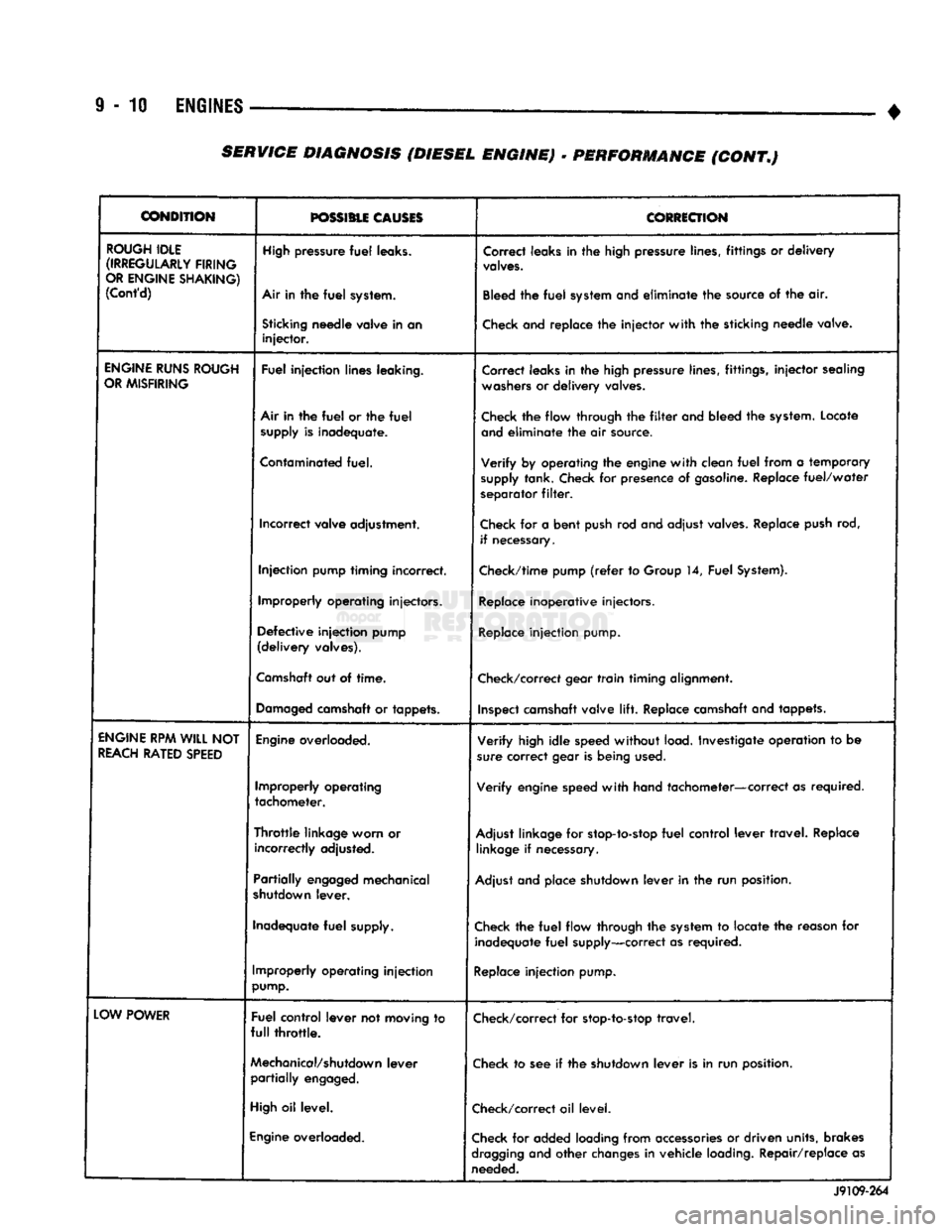
ROUGH
IDLE
(IRREGULARLY
FIRING
OR
ENGINE
SHAKING)
(Cont'd)
High
pressure
fuel
leaks.
Air In the
fuel
system.
Correct leaks in the high pressure lines, fittings or
delivery
valves.
Bleed the
fuel
system and
eliminate
the source of the air.
Sticking
needle
valve
in an
injector.
Check and replace the
injector
with
the sticking
needle
valve.
ENGINE
RUNS
ROUGH
OR
MISFIRING
Fuel
injection
lines
leaking.
Correct leaks in the high pressure lines, fittings,
injector
sealing
washers
or
delivery
valves.
Air in the
fuel
or the
fuel
supply
is
inadequate.
Check the flow through the
filter
and bleed the system. Locate
and
eliminate
the air source.
Contaminated
fuel.
Verify
by operating the engine
with
clean
fuel
from a temporary
supply
tank. Check for presence of gasoline. Replace
fuel/water
separator
filter.
Incorrect
valve
adjustment.
Check for a
bent
push rod and adjust valves. Replace push rod,
if necessary.
Injection
pump
timing
incorrect.
Check/time pump
(refer
to Group 14,
Fuel
System).
Improperly
operating
injectors.
Replace inoperative injectors.
Defective
injection
pump
(delivery
valves).
Replace
injection
pump.
Camshaft
out of
time.
Check/correct gear
train
timing alignment.
Damaged
camshaft or
tappets.
Inspect camshaft valve
lift.
Replace camshaft and tappets.
ENGINE
RPM WILL NOT
REACH
RATED
SPEED
Engine
overloaded.
Verify
high
idle
speed
without
load. Investigate operation to be
sure correct gear is being used.
Improperly
operating
tachometer.
Verify
engine speed
with
hand tachometer—correct as required.
Throttle
linkage
worn
or
incorrectly
adjusted.
Adjust linkage for stop-to-stop
fuel
control
lever
travel.
Replace
linkage if necessary.
Partially
engaged
mechanical
shutdown
lever.
Adjust and place shutdown
lever
in the run position.
Inadequate
fuel
supply. Check the
fuel
flow through the system to locate the reason for
inadequate
fuel
supply—correct as required.
Improperly
operating
injection
pump.
Replace
injection
pump.
LOW
POWER
Fuel
control
lever
not
moving
to
full
throttle.
Check/correct for stop-to-stop
travel.
Mechanical/shutdown
lever
partially
engaged.
Check to see if the shutdown
lever
is in run position.
High
oil
level.
Check/correct oil level.
Engine
overloaded.
Check for added loading from accessories or driven units, brakes
dragging
and
other
changes in vehicle loading. Repair/replace as
needed.
J9109-264
SERVICE
DIAGNOSIS (DIESEL ENGINE)
•
PERFORMANCE (CONT.)
Page 619 of 1502
9
- 14
ENGINES
— — — •
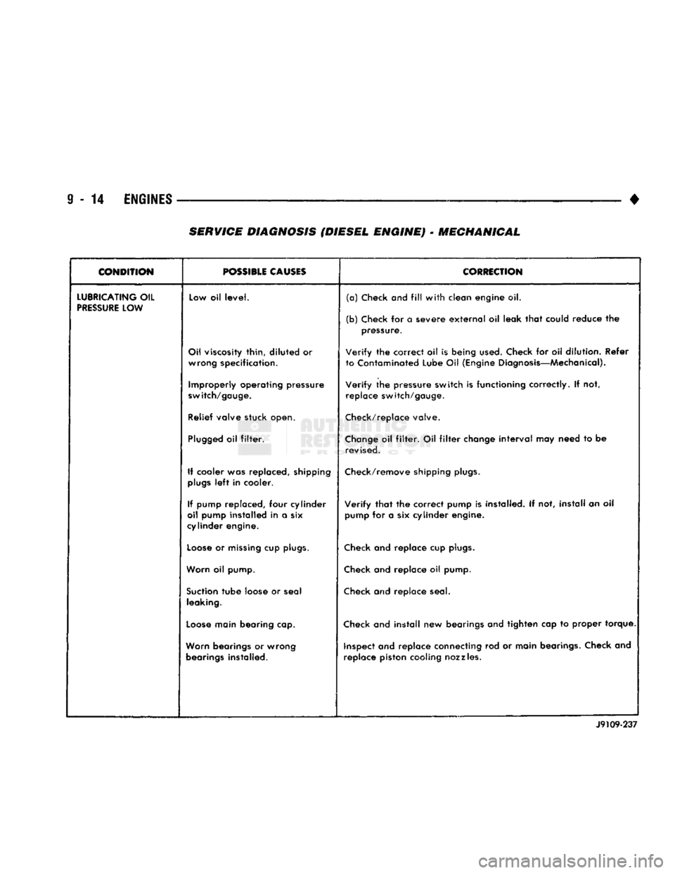
SERVICE
DIAGNOSIS (DIESEL ENGINE)
•
MECHANICAL
CONDITION
r— ———
POSSIBLE
CAUSES
CORRECTION
LUBRICATING
OIL
PRESSURE
LOW Low oil
level.
(a)
Check
and
fill
with
clean engine oil.
(b) Check for a severe
external
oil leak
that
could reduce the pressure.
Oil viscosity thin,
diluted
or wrong specification.
Verify
the correct oil is being
used.
Check for oil dilution. Refer
to Contaminated Lube Oil (Engine Diagnosis—Mechanical).
Improperly operating pressure
switch/gauge.
Verify
the pressure switch is functioning correctly. If not,
replace switch/gauge.
Relief valve stuck open. Check/replace valve.
Plugged
oil
filter.
Change
oil
filter.
Oil
filter
change
interval
may need to be
revised.
If cooler was replaced, shipping
plugs
left
in cooler. Check/remove shipping
plugs.
If pump replaced, four cylinder
oil pump installed in a six
cylinder engine.
Verify
that
the correct pump is installed. If not, install an oil
pump for a six cylinder engine.
Loose
or
missing
cup
plugs.
Check and replace cup
plugs.
Worn oil pump. Check and replace oil pump.
Suction
tube
loose or seal leaking. Check and replace seal.
Loose
main bearing cap. Check and
install
new bearings and tighten cap to proper torque.
Worn bearings or wrong bearings installed. inspect and replace connecting rod or main bearings. Check and
replace piston cooling nozzles.
J9109-237
Page 620 of 1502
•
• —
ENGINES
9 - 15
CONDITION
POSSIBLE CAUSES
CORRECTION
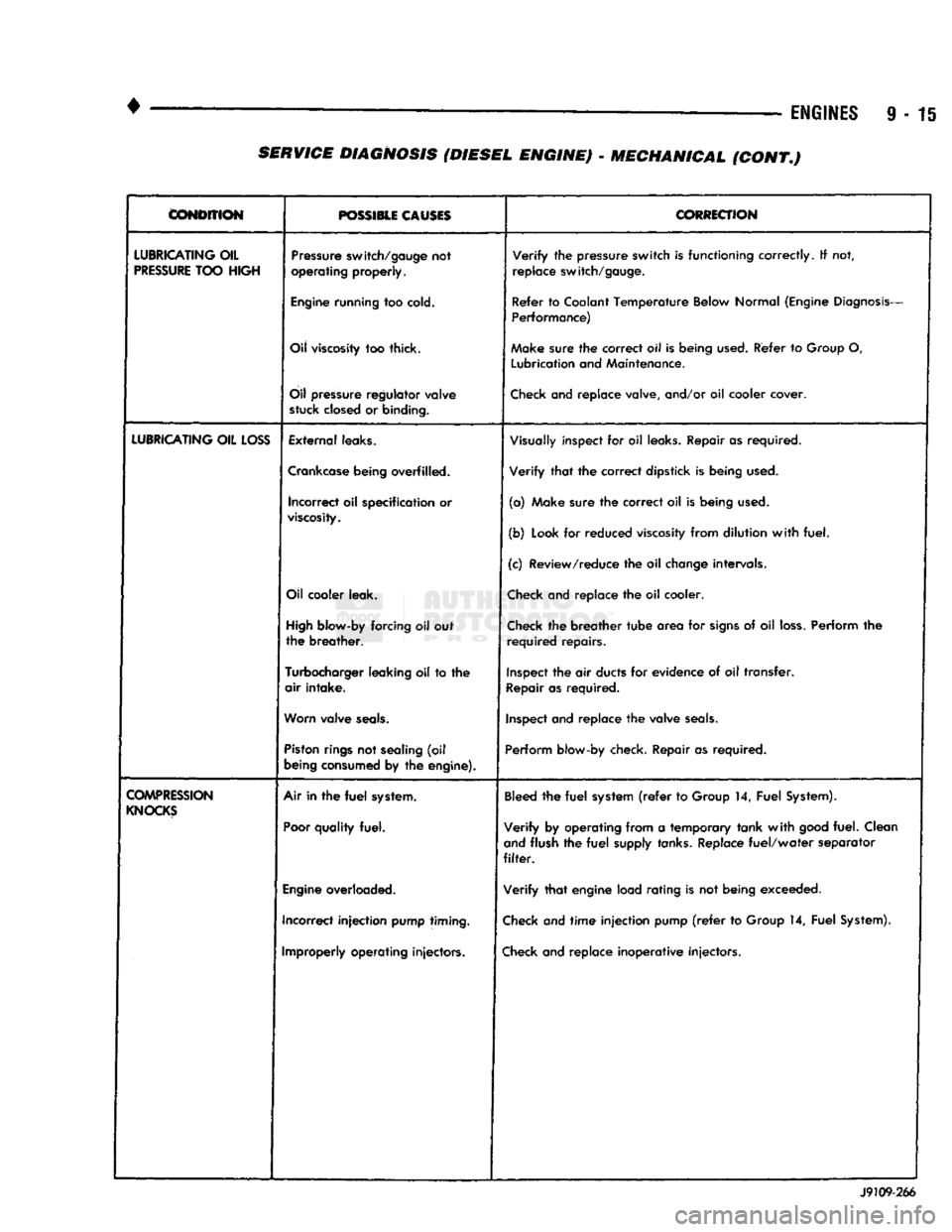
LUBRICATING
OIL
PRESSURE
TOO
HIGH
Pressure
switch/gauge
not
operating
properly.
Verify
the
pressure
switch
is
functioning
correctly.
If not,
replace
switch/gauge.
Engine
running
too
cold.
Refer
to
Coolant
Temperature
Below
Normal
(Engine
Diagnosis-
Performance)
Oil
viscosity
too thick. Make
sure
the
correct
oil Is
being
used.
Refer
to
Group
O,
Lubrication
and
Maintenance.
Oil
pressure
regulator
valve
stuck
closed
or
binding.
Check
and replace valve, and/or oil cooler cover.
LUBRICATING
OIL
LOSS
External
leaks.
Visually
inspect for oil
leaks.
Repair as required.
Crankcase
being
overfilled. Verify that the correct dipstick is being
used.
incorrect
oil specification or
viscosity.
(a) Make sure the correct oil is being
used.
(b)
Look
for reduced
viscosity
from dilution with fuel.
(c) Review/reduce the oil
change
intervals.
Oil
cooler
leak.
Check
and replace the oil cooler.
High
blow-by
forcing oil out
the breather.
Check
the breather tube area for
signs
of oil
loss.
Perform the
required repairs.
Turbocharger
leaking
oil to the
air intake.
Inspect
the air
ducts
for evidence of oil transfer.
Repair
as required.
Worn
valve
seals.
Inspect
and replace the valve
seals.
Piston
rings
not
sealing
(oil
being
consumed
by the
engine).
Perform
blow-by check. Repair as required.
COMPRESSION
KNOCKS
Air in the
fuel
system.
Poor
quality
fuel.
Bleed
the fuel
system
(refer
to
Group
14, Fuel
System).
Verify by operating from a temporary tank with
good
fuel. Clean
and
flush the fuel
supply
tanks.
Replace fuel/water separator
filter.
Engine
overloaded. Verify that engine load rating is not being exceeded.
Incorrect injection
pump
timing.
Check
and time injection pump
(refer
to
Group
14, Fuel
System).
Improperly
operating
injectors.
Check
and replace inoperative injectors. J9109-266 SERVICE DIAGNOSIS (DIESEL ENGINE) - MECHANICAL (CONT.)
Page 622 of 1502
•
3.9L ENGINE
9 - 17
3.9L
ENGINE SERVICE PROCEDURES
INDEX
page
Camshaft
31
Crankshaft
38
Crankshaft Main Bearings
39
Crankshaft Rear
Oil
Seals
. 40
Cylinder Block
41
Cylinder Head Cover
. , 21
Cylinder Heads
. 22
Distributor
33
Engine
Assembly .........................
20
Engine
Front Mounts
17
Engine
Rear Mount
18
Front Crankshaft
Oil
Seal Replacement ........
31
GENERAL INFORMATION
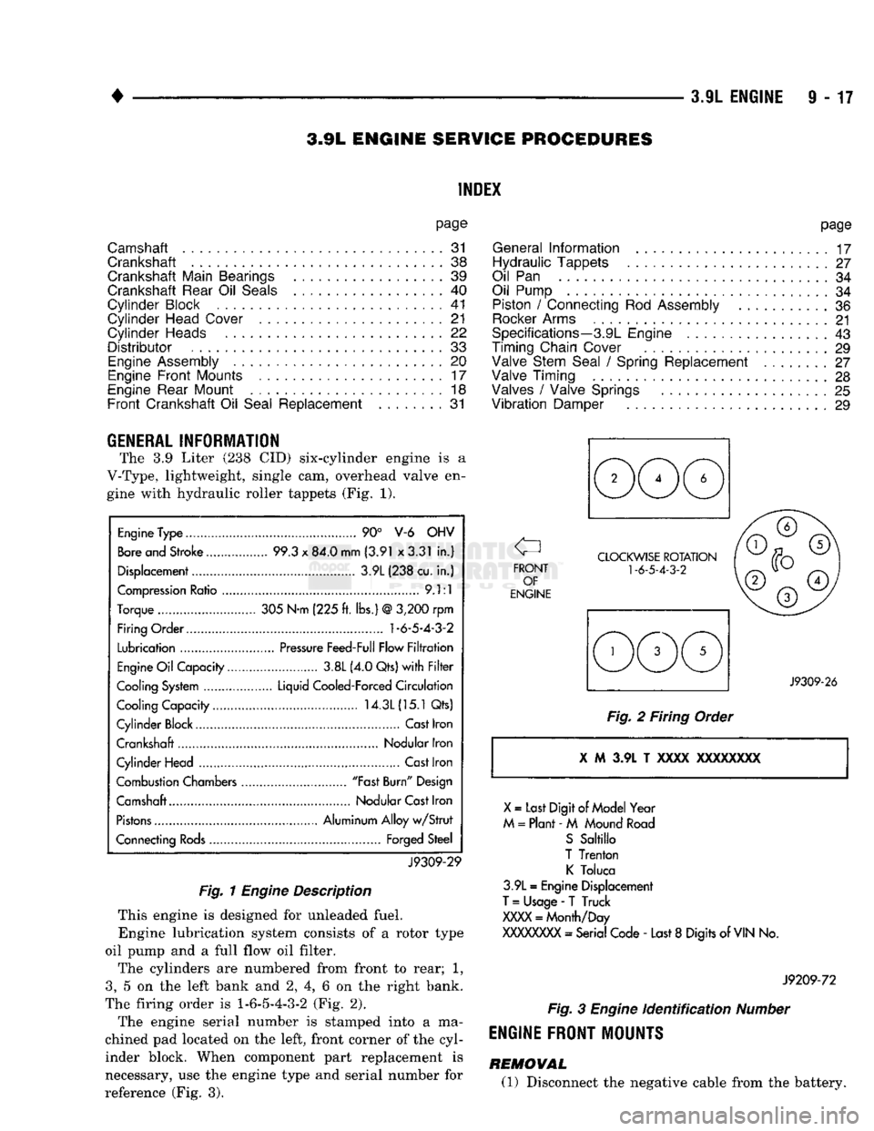
The 3.9 Liter (238 CID) six-cylinder engine is a
V-Type, lightweight, single cam, overhead valve en gine with hydraulic roller tappets (Fig. 1).
Engine
Type
90° V-6 OHV
Bore
and Stroke 99.3
x
84.0 mm (3.91 x3.31
in.)
Displacement 3.9L (238 cu.
in.)
Compression
Ratio
9.1:1
Torque 305 N-m (225
ft.
lbs.)
@
3,200
rpm
Firing Order.... 1-6-5-4-3-2
Lubrication
Pressure
Feed-Full Flow
Filtration
Engine
Oil
Capacity 3.8L (4.0 Qts)
with Filter
Cooling
System
Liquid Cooled-Forced
Circulation
Cooling Capacity 14.3L
(15.1
Qts)
Cylinder Block Cast Iron
Crankshaft Nodular Iron
Cylinder Head
Cast
Iron
Combustion Chambers "Fast
Burn"
Design
Camshaft Nodular
Cast
Iron
Pistons
Aluminum Alloy
w/Strut
Connecting
Rods
Forged Steel
J9309-29
Fig.
1
Engine
Description
This engine is designed for unleaded fuel. Engine lubrication system consists of a rotor type
oil pump and a full flow oil filter.
The cylinders are numbered from front to rear; 1,
3,
5 on the left bank and 2, 4, 6 on the right bank.
The firing order is
1-6-5-4-3-2
(Fig. 2).
The engine serial number is stamped into a ma
chined pad located on the left, front corner of the cyl
inder block. When component part replacement is
necessary, use the engine type and serial number for
reference (Fig. 3).
page
General
Information
17
Hydraulic Tappets
27
Oil
Pan 34
Oil Pump
34
Piston
/
Connecting
Rod
Assembly
36
Rocker
Arms
21
Specifications—3.9L Engine
43
Timing Chain Cover
29
Valve Stem Seal
/
Spring Replacement ........
27
Valve Timing
28
Valves
/
Valve Springs
25
Vibration
Damper
29
J9309-26
Fig.
2 Firing Order i M 3.9L T xxxx
XXXXXXXX
X
=
Last Digit
of
Model Year
M
=
Plant -
M
Mound
Road
S
Sabillo
T Trenton
K
Toluca
3.9L
=
Engine Displacement
T
=
Usage
-
T Truck
XXXX
=
Month/Day
XXXXXXXX
- Serial Code -
Last
8
Digits of
VIN
No.
J9209-72
Fig.
3
Engine
identification
Number
ENGINE FRONT MOUNTS
REMOVAL (1) Disconnect the negative cable from the battery.
Page 646 of 1502
•
3.9L ENGINE
9 - 41 (3) Remove the rear main bearing cap. Remove
and discard the old lower oil seal.
(4) Carefully remove and discard the old upper oil
seal.
(5) Lightly oil the new upper seal lips with engine
oil.
To allow ease of installation of the seal, loosen at
least the 2 main bearing caps forward of the rear
bearing cap.
(6) Rotate the new upper seal into the cylinder
block being careful not to shave or cut the outer sur face of the seal. To assure proper installation, use the installation tool provided with the kit. Install the
new seal with the yellow paint facing towards the
rear of the engine.
(7) Install the new lower rear bearing oil seal into
the bearing cap with the yellow paint facing towards
the rear of the engine.
(8) Apply 5 mm (0.20 in) drop of Loctite 515, or
equivalent, on each side of the rear main bearing cap (Fig. 16). Do not over apply sealant or allow the seal
ant to contact the rubber seal. Assemble bearing cap
to cylinder block immediately after sealant applica
tion. Be sure the yellow paint faces toward the rear of the engine.
(9) To align the bearing cap, use cap slot, align
ment dowel and cap bolts. Do not remove excess ma
terial after assembly. Do not strike rear cap more
than 2 times for proper engagement.
(10) Install the rear main bearing cap with cleaned
and oiled cap bolts. Alternately tighten ALL cap
bolts to 115 N-m (85 ft. lbs.) torque.
(11) Install oil pump.
(12) Apply Mopar Silicone Rubber Adhesive Seal
ant, or equivalent, at bearing cap to block joint to
provide cap to block and oil pan sealing (Fig. 17). Ap
ply enough sealant until a small amount is squeezed out. Withdraw nozzle and wipe excess sealant off the
oil pan seal groove.
(13) Immediately install the oil pan.
LOWER SEAL REPLACEMENT
(1) Remove the oil pan.
(2) Remove the oil pump from the rear main bear
ing cap.
(3) Remove the rear main bearing cap and discard
the old lower seal.
(4) Carefully install a new upper seal (refer to Up
per Seal Replacement - Crankshaft Installed proce dure above).
(5) Lightly oil the new lower seal lips with engine
oil.
(6) Install a new lower seal in bearing cap with
yellow paint facing the rear of engine. (7) Apply 5 mm (0.20 in) drop of Loctite 515, or
equivalent, on each side of the rear main bearing cap (Fig. 16). Do not over apply sealant or allow the seal ant to contact the rubber seal. Assemble bearing cap
to cylinder block immediately after sealant applica tion.
(8) To align the bearing cap, use cap slot, align
ment dowel and cap bolts. Do not remove excess ma
terial after assembly. Do not strike rear cap more
than 2 times for proper engagement.
(9) Install the rear main bearing cap with cleaned
and oiled cap bolts. Alternately tighten the cap bolts
to 115 Nnn (85 ft. lbs.) torque.
(10) Install oil pump.
(11) Apply Mopar Silicone Rubber Adhesive Seal
ant, or equivalent, at bearing cap to block joint to
provide cap to block and oil pan sealing (Fig. 17). Ap
ply enough sealant until a small amount is squeezed out. Withdraw nozzle and wipe excess sealant off the
oil pan seal groove.
(12) Immediately install the oil pan.
CYLINDER
BLOCK
Remove the engine assembly from the vehicle.
DISASSEMBLE
(1) Remove the cylinder head. (2) Remove the oil pan.
(3) Remove the piston/connecting rod assembly.
CLEANING
Clean cylinder block thoroughly and check all core
hole plugs for evidence of leaking.
INSPECTION
Examine block for cracks or fractures.
The cylinder walls should be checked for
out-of-
round and taper with Cylinder Bore Indicator Tool C-119. The cylinder block should be bored and honed
with new pistons and rings fitted if:
• The cylinder bores show more than 0.127 mm (0.005 inch) out-of-round.
• The cylinder bores show a taper of more than 0.254 mm (0.010 inch).
• The cylinder walls are badly scuffed or scored. Boring and honing operation should be closely co
ordinated with the fitting of pistons and rings so specified clearances may be maintained.
Refer to Standard Service Procedures in the begin
ning of this Group for the proper honing of cylinder
bores.
OIL LINE PLUG
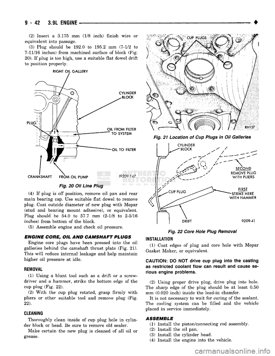
The oil line plug is located in the vertical passage
at the rear of the block between the Oil-To-Filter and
Oil-From-Filter passages (Fig. 20). Improper installa
tion or plug missing could cause erratic, low or no oil pressure.
(1) Remove oil pressure sending unit from back of
block.
Page 647 of 1502
(2) Insert a 3.175 mm (1/8 inch) finish wire or
equivalent into passage.
(3) Plug should be 192.0 to 195.2 mm (7-1/2 to
7-11/16 inches) from machined surface of block (Fig.
20).
If plug is too high, use a suitable flat dowel drift
to position properly.
RIGHT
OIL
GALLERY
CYLINDER
BLOCK
PLUG
OIL
FROM
FILTER
TO
SYSTEM
OIL
TO
FILTER
CRANKSHAFT
FROM
OIL
PUMP
J9209-147
Fig.
20 Oil
Line
Plug
(4) If plug is off position, remove oil pan and rear
main bearing cap. Use suitable flat dowel to remove
plug. Coat outside diameter of new plug with Mopar (stud and bearing mount adhesive), or equivalent.
Plug should be 54.0 to 57.7 mm (2-1/8 to 2-5/16 inches) from bottom of the block.
(5) Assemble engine and check oil pressure.
ENGINE
CORE,
OIL AND
CAMSHAFT
PLUGS
Engine core plugs have been pressed into the oil
galleries behind the camshaft thrust plate (Fig. 21).
This will reduce internal leakage and help maintain
higher oil pressure at idle.
REMOWAL
(1) Using a blunt tool such as a drift or a screw
driver and a hammer, strike the bottom edge of the
cup plug (Fig. 22).
(2) With the cup plug rotated, grasp firmly with
pliers or other suitable tool and remove plug (Fig.
22).
CLEANING
* Thoroughly clean inside of cup plug hole in cylin
der block or head. Be sure to remove old sealer.
Make certain the new plug is cleaned of all oil or
grease. RH157
Fig.
21 Location of Cup
Plugs
in Oil Galleries Jr
CYLINDER
^
BLOCK
/
SECOND
REMOVE
PLUG
WITH
PLIERS
FIRST
STRIKE
HERE
WITH
HAMMER
DRIFT
9209-41
Fig.
22
Core
Hole
Plug
Removal
INSTALLATION
(1) Coat edges of plug and core hole with Mopar
Gasket Maker, or equivalent.
CAUTION:
DO NOT drive cup
plug
into the
casting
as
restricted
coolant
flow can result and
cause
se
rious
engine
problems.
(2) Using proper drive plug, drive plug into hole.
The sharp edge of the plug should be at least 0.50 mm (0.020 inch) inside the lead-in chamfer. It is not necessary to wait for curing of the sealant.
The cooling system can be filled and the vehicle
placed in service immediately.
ASSEMBLE
(1) Install the piston/connecting rod assembly.
(2) Install the oil pan.
(3) Install the cylinder head.
(4) Install the engine into the vehicle.