1993 DODGE TRUCK oil filter
[x] Cancel search: oil filterPage 802 of 1502
FRAME
AND
BUMPERS
13 - 15
LEGEND
FOR FIG. 9
1.
Plastic
Washer
2. Locknut
3. Pressure Relief Valve
4.
Filler
Plug
5.
Cover
arid
Seal
6.
O-Rirtg Seal
7. Sleeve 8. Washer
9. Ram
10. Piston
11.
Packing Cup
12. Piston Follower
13. Locknut
14. Motor
15. Shaft Seat If. 'imp Housing
V/. pcppet
18. Spring
19. Guide
20. Retainer
21.
Setscrew
22. Aluminum Washer
23. Jamnut
24. Acorn N ut
25. Stud
26.
Brass
Washer
27. 2-Way Solenoid
28. 2-Way Coil
29. 2-Way Valve
30.
Ease
and Strainer
COVER
ASSEMBLY
TANK
RESERVOIR
CYLINDER
I
3
PISTON
LOCKNUT
I i
O-RING
RAM
S
PACKINC
WASHER
CUP
PISTON
FOLLOWER
RB531
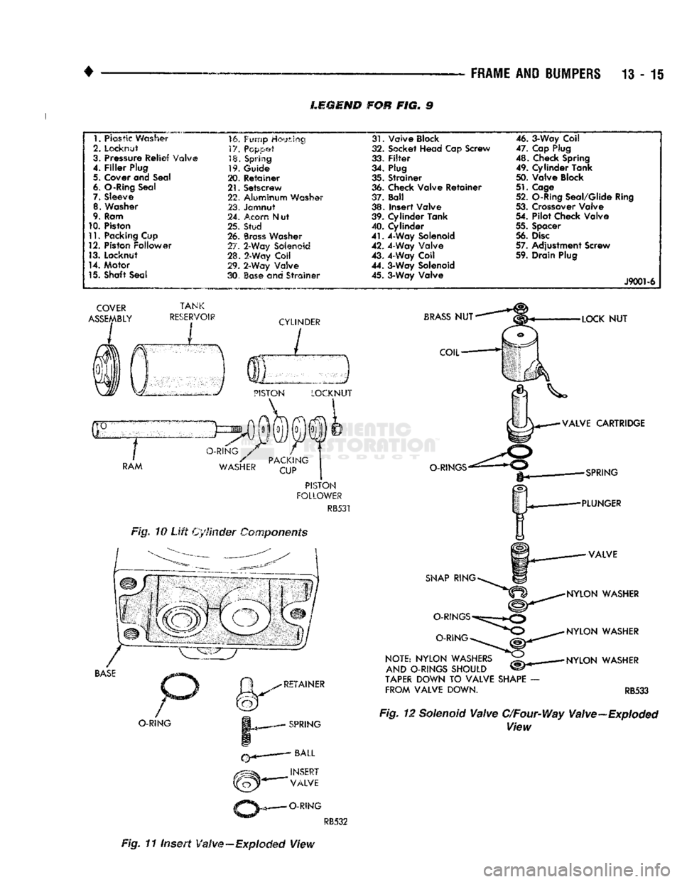
Fig. 10
Lift
Cylinder Components
BASE
O-RING
RETAINER
SPRING
NSERT
VALVE
O-RING
31.
Valve Block
32. Socket Head Cap Screw
33.
Filter
34. Plug
35. Strainer
36. Check Valve Retainer
37. Ball
38. Insert Valve
39. Cylinder Tank
40. Cylinder
41.
4-Way Solenoid
42. 4-Way Valve
43. 4-Way Coil
44. 3-Way Solenoid 45. 3-Way Valve 46. 3-Way Coil
47. Cap Plug
48. Check Spring
49. Cylinder Tank
50. Valve Block
51.
Cage
52. O-Ring Seal/Glide Ring
53. Crossover Valve
54. Pilot Check Valve
55. Spacer
56.
Disc
57. Adjustment Screw
59. Drain Plug
J9001-6
BRASS
NUT
COIL
O-RINGS
SNAP
RING
O-RINGS
O-RING
NOTE:
NYLON
WASHERS
AND
O-RINGS
SHOULD
TAPER
DOWN TO
VALVE
SHAPE
FROM
VALVE
DOWN.
LOCK
NUT
VALVE
CARTRIDGE
SPRING
PLUNGER
VALVE
NYLON
WASHER
NYLON
WASHER
NYLON
WASHER
RB533 Fig. 12 Solenoid
Valve
C/Four-Way Valve-Exploded
View
RB532
Fig. 11 Insert
Valve
—Exploded
View
Page 859 of 1502
14
- 40
FUEL
SYSTEM
• • Park/Neutral switch (gear indicator signal—auto,
trans,
only)
• Oxygen (02) sensor(s) Based on these inputs, the following occurs:
• Voltage is applied to the fuel injectors with the
PCM. The PCM will then adjust the injector pulse
width by turning the ground circuit to each individ
ual injector on and off.
• The PCM monitors the 02 sensor(s) input and ad
justs air-fuel ratio. It also adjusts engine idle speed through the idle air control (IAC) motor.
• The PCM adjusts ignition timing by turning the
ground path to the coil on and off.
• The PCM operates the A/C compressor clutch
through the clutch relay. This happens if A/C has
been selected by the vehicle operator and requested
by the A/C thermostat.
ACCELERATION MODE
This is an Open Loop mode. The powertrain control
module (PCM) recognizes an abrupt increase in
throttle position or MAP pressure as a demand for
increased engine output and vehicle acceleration.
The PCM increases injector pulse width in response
to increased throttle opening.
DECELERATION MODE
When the engine is at operating temperature, this
is an Open Loop mode. During hard deceleration, the
powertrain control module (PCM) receives the follow ing inputs.
• Air conditioning select signal (if equipped)
• Air conditioning request signal (if equipped)
• Battery voltage
• Engine coolant temperature sensor
• Crankshaft position sensor
• Intake manifold charge air temperature sensor
• Manifold absolute pressure (MAP) sensor
• Throttle position sensor (TPS)
• Camshaft position sensor signal (in the distributor)
• Park/Neutral switch (gear indicator signal —auto,
trans,
only)
If the vehicle is under hard deceleration with the
proper rpm and closed throttle conditions, the PCM
will ignore the oxygen sensor input signal. The PCM
will enter a fuel cut-off strategy in which it will not supply battery voltage to the injectors. If a hard de
celeration does not exist, the PCM will determine the
proper injector pulse width and continue injection.
Based on the above inputs, the PCM will adjust en
gine idle speed through the idle air control (IAC) mo
tor. The PCM adjusts ignition timing by turning the
ground path to the coil on and off.
The PCM opens the ground circuit to the A/C
clutch relay to disengage the A/C compressor clutch.
This is done until the vehicle is no longer under de
celeration (if the A/C system is operating).
WIDE OPEN
THROTTLE
MODE
This is an Open Loop mode. During wide open
throttle operation, the powertrain control module (PCM) receives the following inputs.
• Battery voltage
• Crankshaft position sensor
• Engine coolant temperature sensor
• Intake manifold charge air temperature sensor
• Manifold absolute pressure (MAP) sensor
• Throttle position sensor (TPS) • Camshaft position sensor signal (in the distributor) During wide open throttle conditions, the following
occurs:
• Voltage is applied to the fuel injectors with the
powertrain control module (PCM). The PCM will
then control the injection sequence and injector pulse
width by turning the ground circuit to each individ ual injector on and off. The PCM ignores the oxygen sensor input signal and provides a predetermined amount of additional fuel. This is done by adjusting
injector pulse width.
• The PCM adjusts ignition timing by turning the
ground path to the coil on and off.
• The PCM opens the ground circuit to the A/C
clutch relay to disengage the A/C compressor clutch.
This will be done for approximately 15 seconds (if the air conditioning system is operating).
If the vehicle has a manual transmission, the up
shift light is operated by the PCM.
IGNITION
SWITCH
OFF
MODE
When ignition switch is turned to OFF position,
the PCM stops operating the injectors, ignition coil,
ASD relay and fuel pump relay.
THROTTLE
BODY
Filtered air from the air cleaner enters the intake
manifold through the throttle body (Fig. 18). Fuel does not enter the intake manifold through the throt
tle body. Fuel is sprayed into the manifold by the fuel injectors. The throttle body is mounted on the
intake manifold. It contains an air control passage (Fig. 19) controlled by an idle air control (IAC) mo
tor. The air control passage is used to supply air for idle conditions. A throttle valve (plate) is used to supply air for above idle conditions. The throttle position sensor (TPS), idle air control
(IAC) motor and manifold absolute pressure sensor
(MAP) are attached to the throttle body. The acceler
ator pedal cable, speed control cable and transmis
sion control cable (when equipped) are connected to
the throttle arm. A (factory adjusted) set screw is used to mechani
cally limit the position of the throttle body throttle
plate. Never attempt to adjust the engine idle speed using this screw. All idle speed functions are
controlled by the PCM.
Page 878 of 1502
•
FUEL SYSTEM
14 - 59
fill
DHADn
HIAf5MflCTipQ
/f|Rn
The powertrain control module (PCM) has been
programmed to monitor many different circuits of the
fuel injection system. If a problem is sensed in a monitored circuit often enough to indicate an actual
problem, a diagnostic trouble code (DTC) is stored.
The DTC will be stored in the PCM memory for eventual display to the service technician. If the
problem is repaired or ceases to exist, the PCM can cels the DTC after 51 engine starts.
Certain criteria must be met for a diagnostic trou
ble code (DTC) to be entered into PCM memory. The criteria may be a specific range of engine rpm, en
gine temperature and/or input voltage to the PCM.
It is possible that a DTC for a monitored circuit
may not be entered into memory even though a mal
function has occurred. This may happen because one
of the DTC criteria for the circuit has not been met. Example: assume that one of the criteria for the
MAP sensor circuit is that the engine must be oper ating between 750 and 2000 rpm to be monitored for
a DTC. If the MAP sensor output circuit shorts to
ground when the engine rpm is above 2400 rpm, a 0
volt input will be seen by the PCM. A DTC will not
be entered into memory because the condition does not occur within the specified rpm range.
A DTC indicates that the powertrain control mod
ule (PCM) has recognized an abnormal signal in a
circuit or the system. A DTC may indicate the result
of a failure, but never identify the failed component
directly.
There are several operating conditions that the
PCM does not monitor and set a DTC for. Refer to
the following Monitored Circuits and Non-Monitored Circuits in this section.
MONITORED
CIRCUITS
The powertrain control module (PCM) can detect
certain problems in the fuel injection system.
Open or Shorted Circuit - The PCM can deter
mine if sensor output (which is the input to PCM) is
within proper range. It also determines if the circuit is open or shorted.
Output Device Current Flow - The PCM senses
whether the output devices are hooked up.
If there is a problem with the circuit, the PCM
senses whether the circuit is open, shorted to ground
(-), or shorted to
(
+
)
voltage.
Oxygen Sensor - The PCM can determine if the
oxygen sensor is switching between rich and lean.
This is, once the system has entered Closed Loop. Re fer to Open Loop/Closed Loop Modes Of Operation in
the Component Description/System Operation section
for an explanation of Closed (or Open) Loop opera tion.
NON-MONITORED CIRCUITS
The PCM does not monitor the following circuits,
systems or conditions that could have malfunctions
that result in driveability problems. A diagnostic trouble code (DTC) may not be displayed for these
conditions.
Fuel Pressure: Fuel pressure is controlled by the
vacuum assisted fuel pressure regulator. The PCM
cannot detect a clogged fuel pump inlet filter, clogged
in-line fuel filter, or a pinched fuel supply or return
line.
However, these could result in a rich or lean
condition causing an oxygen sensor DTC to be stored in the PCM.
Secondary Ignition Circuit: The PCM cannot de
tect an inoperative ignition coil, fouled or worn spark
plugs,
ignition cross firing, or open circuited spark
plug cables.
Engine Timing: The PCM cannot detect an incor
rectly indexed timing chain, camshaft sprocket or crankshaft sprocket. The PCM also cannot detect an
incorrectly indexed distributor. However, these could
result in a rich or lean condition causing an oxygen
sensor DTC to be stored in the PCM.
Cylinder Compression: The PCM cannot detect
uneven, low, or high engine cylinder compression.
Exhaust System: The PCM cannot detect
a
plugged, restricted or leaking exhaust system.
Fuel Injector Malfunctions: The PCM cannot de
termine if the fuel injector is clogged, or the wrong injector is installed. However, these could result in a
rich or lean condition causing an oxygen sensor DTC
to be stored in the PCM.
Excessive Oil Consumption: Although the PCM
monitors exhaust stream oxygen content through ox
ygen sensor (closed loop), it cannot determine exces sive oil consumption.
Throttle Body Air Flow: The PCM cannot detect
a clogged or restricted air cleaner inlet or air filter
element.
Evaporative System: The PCM will not detect a
restricted, plugged or loaded EVAP canister. Vacuum Assist: Leaks or restrictions in the vac
uum circuits of vacuum assisted engine control sys
tem devices are not monitored by the PCM. However, a vacuum leak at the MAP sensor will be monitored
and a diagnostic trouble code (DTC) will be gener
ated by the PCM.
Powertrain Control Module (PCM) System
Ground: The PCM cannot determine a poor system
ground. However, a DTC may be generated as a re
sult of this condition.
Powertrain Control Module (PCM) Connector
Engagement: The PCM cannot determine spread or
damaged connector pins. However, a DTC may be generated as a result of this condition.
Page 883 of 1502
MULTI-PORT
FUEL
INJECTION
(MPI)-COMPONENT
REMOVAL/INSTALLATION
—EXCEPT DIESEL
INDEX
page
Accelerator Pedal
and Throttle
Cable
. 64
Air Conditioning (A/C) Clutch Relay
64
Air
Filter/Filter
Housing
64
Automatic Shut Down (ASD) Relay
. 64
Brake
Switch
64
Camshaft
Position
Sensor
..................
64
Charge
Air
Temperature
Sensor
64
Crankshaft Position
Sensor
64
Engine
Coolant Temperature
Sensor
65
EVAP
Canister Purge Solenoid
65
Fuel
Filter
65
Fuel Filter/Fuel Pressure Regulator—5.9L Engine
. 65
Fuel Injector(S)
67
Fuel Pressure Regulator
67
Fuel Pump Module
68
Fuel Pump Relay
68
ACCELERATOR
PEDAL
AND THROTTLE
CABLE
Refer
to
the
Accelerator Pedal
and
Throttle Cable
section
of
this group
for
removal/installation proce
dures.
AIR
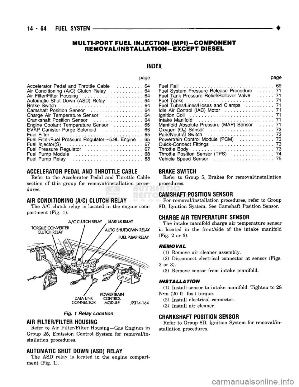
CONDITIONING (A/C) CLUTCH RELAY The A/C clutch relay
is
located
in
the
engine com
partment (Fig.
1).
A/C CLUTCH RELAY STARTER RELAY
DATA LINK CONTROL
CONNECTOR MODULE
J9314-164
Fig.
1 Relay Location
AIR
FILTER/FILTER
HOUSING
Refer
to
Air Filter/Filter Housing—Gas Engines
in
Group
25,
Emission Control System
for
removal/in
stallation procedures.
AUTOMATIC SHUT DOWN (ASD) RELAY The ASD relay
is
located
in
the
engine compart
ment (Fig.
1).
page
Fuel Rail
69
Fuel System Pressure Release Procedure
......
71
Fuel Tank Pressure Relief/Rollover Valve
71
Fuel Tanks
71
Fuel
Tubes/Lines/Hoses
and
Clamps
71
Idle
Air
Control (IAC) Motor
71
Ignition Coil
71
Intake Manifold
71
Manifold Absolute Pressure (MAP)
Sensor
71
Oxygen
(02)
Sensor
72
Park/Neutral Switch
. 73
Powertrain Control Module (PCM)
73
Quick-Connect
Fittings
73
Throttle
Body
73
Throttle
Position
Sensor
(TPS)
......
74
Vehicle
Speed
Sensor
75
BRAKE
SWITCH
Refer
to
Group
5,
Brakes
for
removal/installation
procedures.
CAMSHAFT
POSITION
SENSOR
For removal/installation procedures, refer
to
Group
8D,
Ignition System. See Camshaft Position Sensor.
CHARGE
AIR
TEMPERATURE SENSOR
The intake manifold charge
air
temperature sensor
is located
in the
front/side
of
the
intake manifold (Fig.
2
or
3).
REMOVAL
(1) Remove
air
cleaner assembly.
(2) Disconnect electrical connector
at
sensor (Figs.
2
or
3). (3) Remove sensor from intake manifold.
INSTALLATION
(1) Install sensor
to
intake manifold. Tighten
to 28
Nnn (20
ft.
lbs.) torque.
(2) Install electrical connector.
(3) Install
air
cleaner.
CRANKSHAFT
POSITION
SENSOR
Refer
to
Group 8D, Ignition System
for
removal/in
stallation procedures.
Page 885 of 1502
14
- 66
FUEL
SYSTEM
REMOVAL
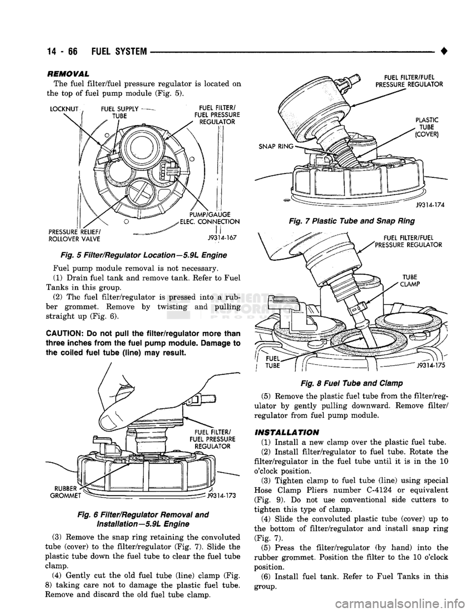
The fuel filter/fuel pressure regulator is located on
the top of fuel pump module (Fig. 5).
ROLLOVER
VALVE
J9314-167
Fig.
5 Filter/Regulator Location—5.9L
Engine
Fuel pump module removal is not necessary. (1) Drain fuel tank and remove tank. Refer to Fuel
Tanks in this group. (2) The fuel filter/regulator is pressed into a rub
ber grommet. Remove by twisting and pulling straight up (Fig. 6).
CAUTION;
Do not pull the
filter/regulator
more
than
three
inches
from
the
fuel
pump
module.
Damage
to
the
coiled
fuel
tube
(line)
may
result.
Fig.
6 Filter/Regulator
Removal
and Installation—5.9L
Engine
(3) Remove the snap ring retaining the convoluted
tube (cover) to the filter/regulator (Fig. 7). Slide the
plastic tube down the fuel tube to clear the fuel tube clamp.
(4) Gently cut the old fuel tube (line) clamp (Fig.
8) taking care not to damage the plastic fuel tube.
Remove and discard the old fuel tube clamp.
Fig.
7 Plastic Tube and
Snap
Ring
Fig.
8
Fuel
Tube and
Clamp
(5) Remove the plastic fuel tube from the filter/reg
ulator by gently pulling downward. Remove filter/
regulator from fuel pump module.
INSTALLATION
(1) Install a new clamp over the plastic fuel tube.
(2) Install filter/regulator to fuel tube. Rotate the
filter/regulator in the fuel tube until it is in the 10 o'clock position. (3) Tighten clamp to fuel tube (line) using special
Hose Clamp Pliers number C-4124 or equivalent (Fig. 9). Do not use conventional side cutters to
tighten this type of clamp.
(4) Slide the convoluted plastic tube (cover) up to
the bottom of filter/regulator and install snap ring (Fig. 7).
(5) Press the filter/regulator (by hand) into the
rubber grommet. Position the filter to the 10 o'clock
position.
(6) Install fuel tank. Refer to Fuel Tanks in this
group.
Page 890 of 1502
•
FUEL SYSTEM
14-71
FUEL SYSTEM PRESSURE RELEASE PROCEDURE
WARNING:
THE
FUEL
SYSTEM
IS
UNDER
A
CON
STANT
PRESSURE
(EVEN
WITH
THE
ENGINE
TURNED
OFF).
BEFORE
SERVICING
THE
FUEL
PUMP,
FUEL
LINES
(TUBES),
FUEL
FILTER,
OR
FUEL
INJECTOR(S),
THE
FUEL
SYSTEM
PRESSURE
MUST
BE
RELEASED.
To release fuel pressure, refer to the Fuel Delivery
System section of this group. See Fuel System Pres
sure Release Procedure.
FUEL TANKS
Refer to the Fuel Tank section of this group for re
moval/installation procedures.
FUEL TANK
PRESSURE
RELIEF/ROLLOVER VALVE
Refer to the Fuel Tank section of this group for re
moval/installation procedures.
FUEL
TUBES/LINES/HOSES
AND CLAMPS
Refer to Fuel Tubes/Lines/Hoses and Clamps in the
Fuel Delivery System section of this group for remov al/installation procedures. Also refer to Quick-Connect Fittings in the Fuel
Delivery System section of this group for removal/in
stallation procedures.
IDLE
AIR
CONTROL
(IAC)
MOTOR
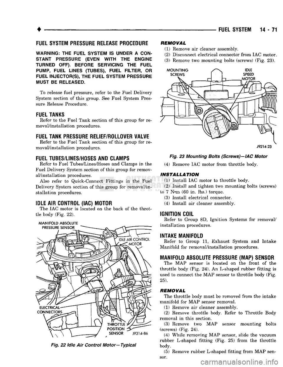
The IAC motor is located on the back of the throt
tle body (Fig. 22).
MANIFOLD ABSOLUTE
Fig.
22
idle
Air Control Motor—Typical
REMOVAL
(1) Remove air cleaner assembly.
(2) Disconnect electrical connector from IAC motor.
(3) Remove two mounting bolts (screws) (Fig. 23).
J9214-23
Fig.
23
Mounting
Bolts
(Screws)—IAC
Motor
(4) Remove IAC motor from throttle body.
INSTALLATION
(1) Install IAC motor to throttle body.
(2) Install and tighten two mounting bolts (screws)
to 7 N»m (60 in. lbs.) torque.
(3) Install electrical connector.
(4) Install air cleaner assembly.
IGNITION COIL
Refer to Group 8D, Ignition Systems for removal/
installation procedures.
INTAKE MANIFOLD
Refer to Group 11, Exhaust System and Intake
Manifold for removal/installation procedures.
MANIFOLD ABSOLUTE
PRESSURE
(MAP)
SENSOR
The MAP sensor is located on the front of the
throttle body (Fig. 24). An L-shaped rubber fitting is
used to connect the MAP sensor to throttle body (Fig.
25).
REMOVAL
The throttle body must be removed from the intake
manifold for MAP sensor removal.
(1) Remove air cleaner assembly.
(2) Remove throttle body. Refer to Throttle Body
removal in this section.
(3) Remove two MAP sensor mounting bolts
(screws) (Fig. 24). (4) While removing MAP sensor, slide the vacuum
rubber L-shaped fitting (Fig. 25) from the throttle
body.
(5) Remove rubber L-shaped fitting from MAP sen
sor.
Page 929 of 1502
14
- 110
FUEL SYSTEM
SENSOR
J9114-39
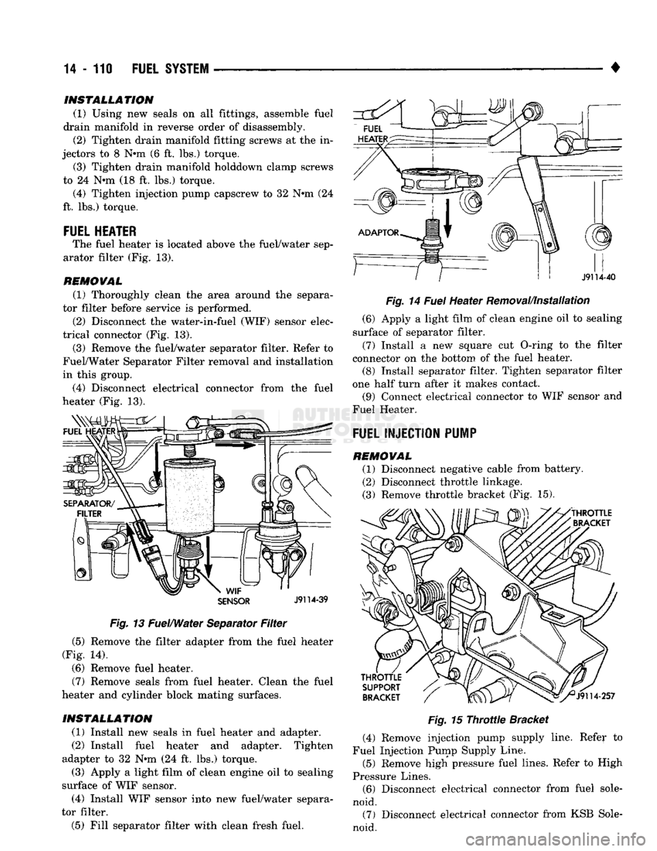
Fig.
13 Fuel/Water Separator
Filter
(5) Remove the filter adapter from the fuel heater
(Fig. 14).
(6) Remove fuel heater.
(7) Remove seals from fuel heater. Clean the fuel
heater and cylinder block mating surfaces.
INSTALLATION
(1) Install new seals in fuel heater and adapter.
(2) Install fuel heater and adapter. Tighten
adapter to 32 Nrn (24 ft. lbs.) torque. (3) Apply a light film of clean engine oil to sealing
surface of WIF sensor.
(4) Install WIF sensor into new fuel/water separa
tor filter.
(5) Fill separator filter with clean fresh fuel. •
Fig.
14
Fuel
Heater Removal/Installation (6) Apply a light film of clean engine oil to sealing
surface of separator filter.
(7) Install a new square cut O-ring to the filter
connector on the bottom of the fuel heater. (8) Install separator filter. Tighten separator filter
one half turn after it makes contact. (9) Connect electrical connector to WIF sensor and
Fuel Heater.
FUEL INJECTION PUMP
REMOVAL (1) Disconnect negative cable from battery.
(2) Disconnect throttle linkage.
(3) Remove throttle bracket (Fig. 15).
Fig.
15
Throttle
Bracket
(4) Remove injection pump supply line. Refer to
Fuel Injection Pump Supply Line.
(5) Remove high pressure fuel lines. Refer to High
Pressure Lines. (6) Disconnect electrical connector from fuel sole
noid. (7) Disconnect electrical connector from KSB Sole
noid.
INSTALLATION
(1) Using new seals on all fittings, assemble fuel
drain manifold in reverse order of disassembly. (2) Tighten drain manifold fitting screws at the in
jectors to 8 N#m (6 ft. lbs.) torque. (3) Tighten drain manifold holddown clamp screws
to 24 N*m (18 ft. lbs.) torque. (4) Tighten injection pump capscrew to 32 N#m (24
ft. lbs.) torque.
FUEL HEATER
The fuel heater is located above the fuel/water sep
arator filter (Fig. 13).
REMOVAL
(1) Thoroughly clean the area around the separa
tor filter before service is performed.
(2) Disconnect the water-in-fuel (WIF) sensor elec
trical connector (Fig. 13). (3) Remove the fuel/water separator filter. Refer to
Fuel/Water Separator Filter removal and installation
in this group.
(4) Disconnect electrical connector from the fuel
heater (Fig. 13).
Page 935 of 1502
14
• 116
FUEL
SYSTEM
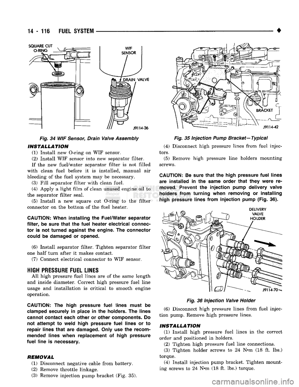
Fig.
34 WIF
Sensor,
Drain
Valve
Assembly
INSTALLATION
(1) Install new O-ring on WIF sensor.
(2) Install WIF sensor into new separator filter.
If the new fuel/water separator filter is not filled
with clean fuel before it is installed, manual air
bleeding of the fuel system may be necessary. (3) Fill separator filter with clean fuel.
(4) Apply a light film of clean unused engine oil to
the separator filter seal.
(5) Install a new square cut O-ring to the filter
connector on the bottom of the fuel heater.
CAUTION:
When installing
the
Fuel/Water separator
filter,
be
sure
that
the
fuel
heater
electrical
connec
tor
is not
turned
against
the
engine.
The
connector could
be
damaged
or
opened.
(6) Install separator filter. Tighten separator filter
one half turn after it makes contact.
(7) Connect electrical connector to WIF sensor.
HIGH
PRESSURE
FUEL LINES
All high pressure fuel lines are of the same length
and inside diameter. Correct high pressure fuel line
usage and installation is critical to smooth engine
operation.
CAUTION:
The
high pressure
fuel
lines must
be
clamped securely
in
place
in the
holders.
The
lines
cannot contact each other
or
other components.
Do
not
attempt
to
weld high pressure
fuel
lines
or to
repair lines
that
are
damaged. Only
use the
recom
mended lines when replacement
of
high pressure
fuel
line
is
necessary.
REMOVAL
(1) Disconnect negative cable from battery.
(2) Remove throttle linkage.
(3) Remove injection pump bracket (Fig. 35).
Fig.
35 Injection
Pump
Bracket—
Typical
(4) Disconnect high pressure lines from fuel injec
tors.
(5) Remove high pressure line holders mounting
screws.
CAUTION:
Be
sure
that
the
high pressure
fuel
lines
are installed
in the
same order
that
they
were
re
moved.
Prevent
the
injection
pump delivery valve
holders from turning when removing
or
installing
high
pressure lines from
injection
pump (Fig.
36).
Fig.
36 Injection
Valve
Holder
(6) Disconnect high pressure lines from fuel injec
tion pump. Remove high pressure lines.
INSTALLATION
(1) Install high pressure fuel lines in the correct
order and positioned in holders.
(2) Tighten high pressure fuel line connections.
(3) Tighten holder screws to 24 N-m (18 ft. lbs.)
torque.
(4) Install injection pump bracket. Tighten mount
ing screws to 24 N*m (18 ft. lbs.) torque.