1993 DODGE TRUCK oil filter
[x] Cancel search: oil filterPage 1232 of 1502
#
s ; _
TRANSMISSION
OWERHAUL—38RH/37RH
21 - 231
washer as needed. Thrust washer is select and
comes in three thicknesses.
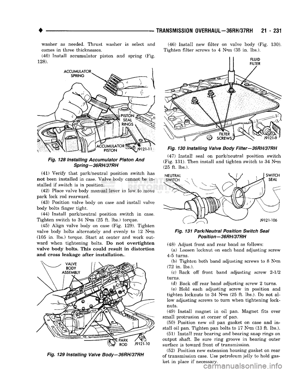
(40) Install accumulator piston and spring (Fig.
128). Fig.
128 Installing
Accumulator
Piston
And
Spring-36RH/37RH
(41) Verify that park/neutral position switch has
not been installed in case. Valve body cannot be in stalled if switch is in position.
(42) Place valve body manual lever in low to move
park lock rod rearward.
(43) Position valve body on case and install valve
body bolts finger tight.
(44) Install park/neutral position switch in case.
Tighten switch to 34 Nnn (25 ft. lbs.) torque.
(45) Align valve body on case (Fig. 129). Tighten
valve body bolts alternately and evenly to 12 Nnn (105 in. lbs.) torque. Start at center and work out
ward when tightening bolts. Do not overtighten
valve body bolts. This could result in distortion and cross leakage after installation..
Fig.
129 Installing
Valve
Body-36RH/37RH
(46) Install new filter on valve body (Fig. 130).
Tighten filter screws to 4 Nnn (35 in. lbs.).
Fig.
130 Installing
Valve
Body
Filter-36RH/37RH
(47) Install seal on park/neutral position switch
(Fig. 131). Then install and tighten switch to 34 Nnn
(25 ft. lbs.).
Fig.
131 Park/Neutral Position
Switch
Seal
Position-36RH/37RH
(48) Adjust front and rear band as follows:
(a) Loosen locknut on each band adjusting screw
4-5 turns. (b) Tighten both band adjusting screws to 8 Nnn
(72 in. lbs.).
(c) Back off front band adjusting screw 2-1/2
turns.
(d) Back off rear band adjusting screw 2 turns.
(e) Hold each adjusting screw in position and
tighten locknuts to 34 Nnn (25 ft. lbs.). Do not al low adjusting screws to turn when tightening lock-
nuts.
(49) Install magnet in oil pan. Magnet fits over
small protrusion at corner of pan. (50) Position new oil pan gasket on case and in
stall oil pan. Tighten pan bolts to 17 Nnn (13 ft. lbs.).
(51) Install rear bearing and bearing snap rings on
output shaft. Be sure ring groove in bearing outer surface is toward front of transmission. (52) Position new extension housing gasket on rear
of transmission case. Use petroleum jelly to hold gas
ket in place if necessary.
Page 1235 of 1502
21
- 234
TRANSMISSION
0VERHAUL-42RH
J9321-133
Fig.
4 Overdrive
Spline
Alignment
Tool
Installation
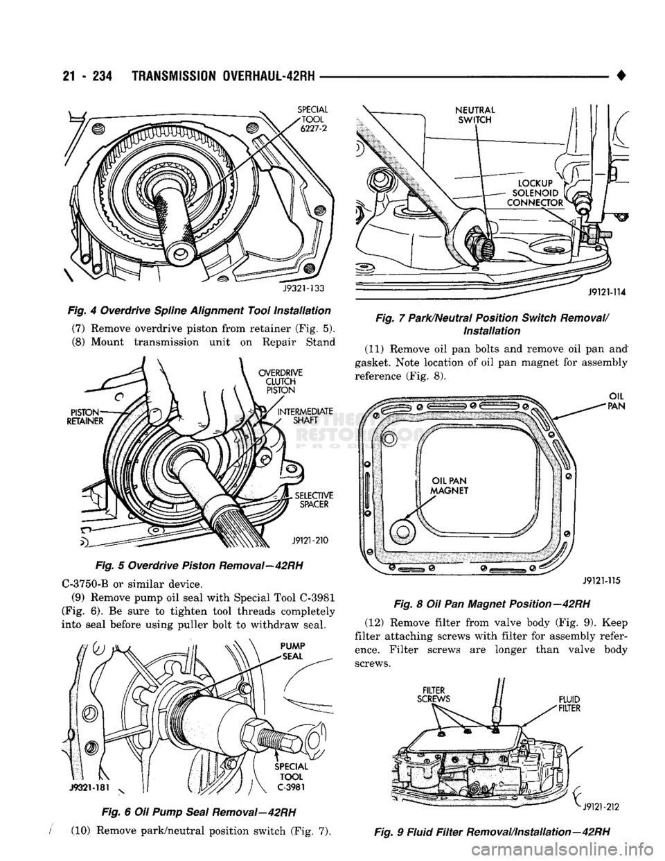
(7) Remove overdrive piston from retainer (Fig. 5).
(8) Mount transmission unit on Repair Stand
Fig.
5 Overdrive
Piston
Removal—42RH C-3750-B or similar device.
(9) Remove pump oil seal with Special Tool C-3981
(Fig. 6). Be sure to tighten tool threads completely
into seal before using puller bolt to withdraw seal.
Fig.
6 Oil
Pump
Seal
Removal—42RH
I
(10) Remove park/neutral position switch (Fig. 7). •
Fig.
7 Park/Neutral Position
Switch
Removal/
Installation
(11) Remove oil pan bolts and remove oil pan and
gasket. Note location of oil pan magnet for assembly reference (Fig. 8).
J9121-115
Fig.
8 Oil Pan Magnet Position—42RH (12) Remove filter from valve body (Fig. 9). Keep
filter attaching screws with filter for assembly refer
ence.
Filter screws are longer than valve body screws.
Fig.
9 Fluid
Filter
Removal/Installation—42RH
Page 1278 of 1502
•
TRANSMISSION
OVERHAUL-42RH
21 - 277 (47) Lubricate intermediate shaft splines and bushing
surfaces with transmission fluid or petroleum jelly.
(48) Install overdrive unit. Be sure governor tubes
are aligned with feed holes in piston retainer boss. Note that intermediate shaft is snug fit in overdrive
planetary gear and overrunning clutch. If overdrive unit will not seat fully, rotate overdrive output shaft slightly to align splines and try again.
(49) Apply 1-2 drops of Mopar thread adhesive (or
Loctite 242) to overdrive unit attaching bolts. Then install and tighten bolts to 34 N« (25 ft. lbs.) torque.
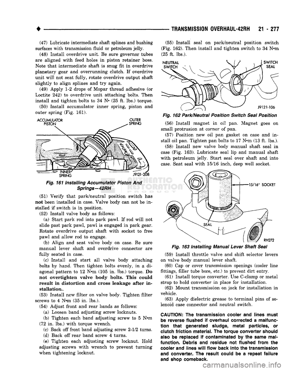
(50) Install accumulator inner spring, piston and
outer spring (Fig. 161).
ACCUMULATOR
OUTER
Fig.
161 Installing
Accumulator
Piston
And
Springs—42RH
(51) Verify that park/neutral position switch has
not been installed in case. Valve body can not be in stalled if switch is in position.
(52) Install valve body as follows: (a) Start park rod into park pawl. If rod will not
slide past park pawl, pawl is engaged in park gear.
Rotate overdrive output shaft with socket to free
pawl and allow rod to engage.
(b) Align and seat valve body on case. Be sure
manual lever shaft and overdrive connector are
fully seated in case.
(c) Install and start all valve body attaching
bolts by hand. Then tighten bolts evenly, in a di agonal pattern to 12 N»m (105 in. lbs.) torque. Do
not overtighten valve body bolts. This could
result in distortion and cross leakage after in stallation..
(53) Install new filter on valve body. Tighten filter
screws to 4 N*m (35 in. lbs.).
(54) Adjust front and rear bands as follows: (a) Loosen band adjusting screw locknuts.
(b) Tighten each band adjusting screw to 5 Nnn
(72 in. lbs.) with torque wrench.
(c) Back off front band adjusting screw 2-1/2 turns.
(d) Back off rear band screw 4 turns.
(e) Tighten each adjusting screw locknut. Hold
adjusting screws with wrench to prevent turning
when tightening locknut. (55) Install seal on park/neutral position switch
(Fig. 162). Then install and tighten switch to 34 N«m
(25 ft. lbs.).
Fig.
162 Park/Neutral Position
Switch
Seal
Position
(56) Install magnet in oil pan. Magnet goes on
small protrusion at corner of pan. (57) Position new oil pan gasket on case and in
stall oil pan. Tighten pan bolts to 17 N*m (13 ft. lbs.).
(58) Install new valve body manual shaft seal in
case (Fig. 163). Lubricate seal lip and manual shaft
with petroleum jelly. Start seal over shaft and into
case.
Seat seal with 15/16 inch, deep well socket.
(59) Install throttle valve and shift selector levers
on valve body manual lever shaft. (60) Cap or cover transmission openings (cooler line
fittings, filler tube bore, etc.) to prevent dirt entry.
(61) Install torque converter. Use C-clamp or metal
strap to hold converter in place for installation. (62) Mount transmission on jack for installation in
vehicle.
(63) Apply dielectric grease to terminal pins of so
lenoid case connector and neutral switch.
CAUTION:
The
transmission
cooler
and
lines
must
be
reverse
flushed
if
overhaul
corrected
a
malfunc
tion
that
generated
sludge,
metal
particles,
or
clutch
friction
material.
The
torque
converter
should
also
be replaced if
contaminated
by the
same
mal
function.
Debris and
residue
not
flushed
from
the
cooler
and
lines
will
flow
back
into
the
transmission
and
converter.
The
result
could
be a
repeat
failure
and
shop
comeback.
Page 1281 of 1502
21
- 280
TRANSMISSION
0VERHAUL-46RH
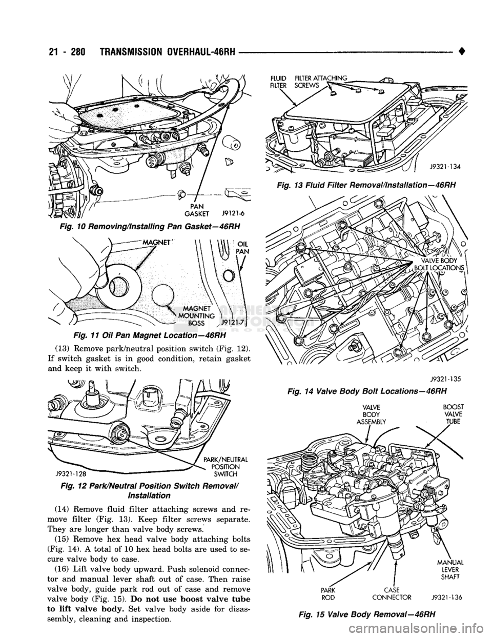
Fig.
11 Oil Pan Magnet Location—46RH (13) Remove park/neutral position switch (Fig. 12).
If switch gasket is in good condition, retain gasket and keep it with switch.
J9321-128
" '
SWITCH
Fig.
12 Park/Neutral Position
Switch
Removal/
Installation
(14) Remove fluid filter attaching screws and re
move filter (Fig. 13). Keep filter screws separate.
They are longer than valve body screws.
(15) Remove hex head valve body attaching bolts
(Fig. 14). A total of 10 hex head bolts are used to se
cure valve body to case.
(16) Lift valve body upward. Push solenoid connec
tor and manual lever shaft out of case. Then raise
valve body, guide park rod out of case and remove valve body (Fig. 15). Do not use boost valve tube
to lift valve body. Set valve body aside for disas sembly, cleaning and inspection.
J9321-135
Fig.
14
Valve
Body
Bolt
Locations—46RH
VALVE BOOST
BODY
VALVE
ASSEMBLY
TUBE
PARK
CASE
ROD
CONNECTOR
J9321-136
Fig.
15
Valve
Body
Removal—46RH
Page 1323 of 1502
21
- 322
TRANSMISSION
OVERHAUL-46RH
•
J932M33
Fig.
155
Checking
Alignment
Of Overdrive Planetary
Gear
And Overrunning
Clutch
Splines—46RH
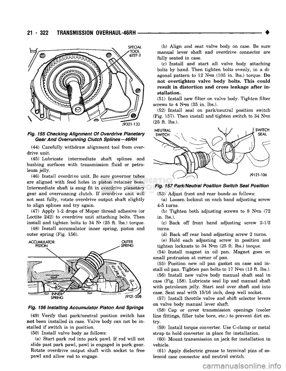
(44) Carefully withdraw alignment tool from over
drive unit.
(45) Lubricate intermediate shaft splines and
bushing surfaces with transmission fluid or petro leum jelly.
(46) Install overdrive unit. Be sure governor tubes
are aligned with feed holes in piston retainer boss.
Intermediate shaft is snug fit in overdrive planetary
gear and overrunning clutch. If overdrive unit will
not seat fully, rotate overdrive output shaft slightly
to align splines and try again.
(47) Apply 1-2 drops of Mopar thread adhesive (or
Loctite 242) to overdrive unit attaching bolts. Then
install and tighten bolts to 34 N» (25 ft. lbs.) torque.
(48) Install accumulator inner spring, piston and
outer spring (Fig. 156).
ACCUMULATOR
OUTER
Fig.
156 Installing
Accumulator
Piston
And
Springs
(49) Verify that park/neutral position switch has
not been installed in case. Valve body can not be in stalled if switch is in position.
(50) Install valve body as follows: (a) Start park rod into park pawl. If rod will not
slide past park pawl, pawl is engaged in park gear.
Rotate overdrive output shaft with socket to free
pawl and allow rod to engage. (b) Align and seat valve body on case. Be sure
manual lever shaft and overdrive connector are
fully seated in case.
(c) Install and start all valve body attaching
bolts by hand. Then tighten bolts evenly, in a di agonal pattern to 12 Nnn (105 in. lbs.) torque. Do
not overtighten valve body bolts. This could result in distortion and cross leakage after in stallation..
(51) Install new filter on valve body. Tighten filter
screws to 4 Nnn (35 in. lbs.).
(52) Install seal on park/neutral position switch
(Fig. 157). Then install and tighten switch to 34 Nnn
(25 ft. lbs.).
Fig.
157 Park/Neutral Position
Switch
Seal
Position
(53) Adjust front and rear bands as follows:
(a) Loosen locknut on each band adjusting screw
4-5 turns.
(b) Tighten both adjusting screws to 8 Nnn (72
in. lbs.).
(c) Back off front band adjusting screw 2-1/2
turns.
(d) Back off rear band adjusting screw 2 turns.
(e) Hold each adjusting screw in position and
tighten locknuts to 34 Nnn (25 ft. lbs.) torque.
(54) Install magnet in oil pan. Magnet goes on
small protrusion at corner of pan.
(55) Position new oil pan gasket on case and in
stall oil pan. Tighten pan bolts to 17 Nnn (13 ft. lbs.).
(56) Install new valve body manual shaft seal in
case (Fig. 158). Lubricate seal lip and manual shaft
with petroleum jelly. Start seal over shaft and into
case.
Seat seal with 15/16 inch, deep well socket.
(57) Install throttle valve and shift selector levers
on valve body manual lever shaft. (58) Cap or cover transmission openings (cooler
line fittings, filler tube bore, etc.) to prevent dirt en
try.
(59) Install torque converter. Use C-clamp or metal
strap to hold converter in place for installation. (60) Mount transmission on jack for installation in
vehicle.
(61) Apply dielectric grease to terminal pins of so
lenoid case connector and neutral switch.
Page 1367 of 1502
21 • 366
TRANSMISSION/TRANSFER
CASE
SPECIFICATIONS
•
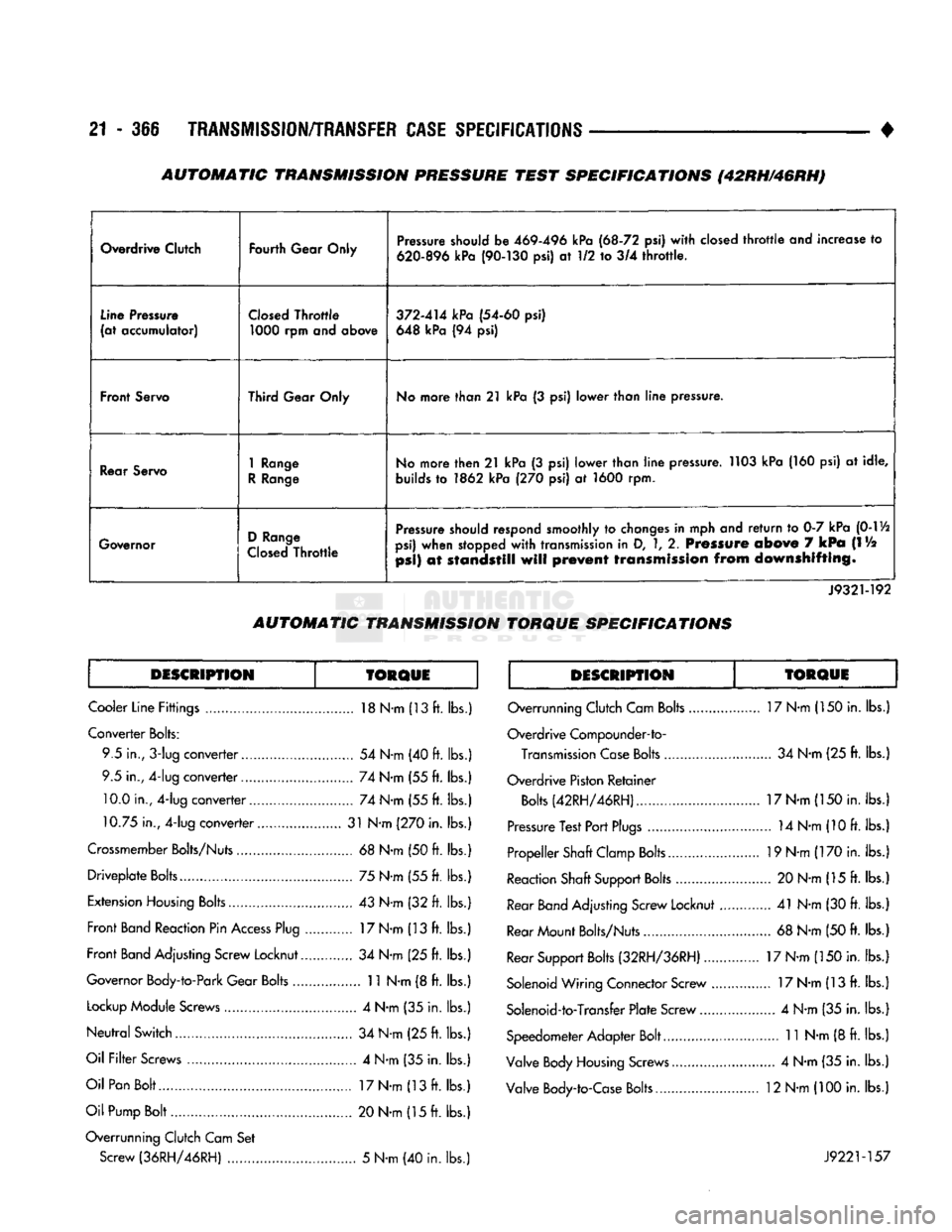
Overdrive Clutch
Fourth Gear Only Pressure should be
469-496
kPa
(68-72
psi) with closed throttle and increase to
620-896
kPa
(90-130
psi) at 1/2 to 3/4 throttle.
Line Pressure
(at accumulator) Closed Throttle
1000
rpm and above
372-414
kPa
(54-60
psi)
648 kPa (94 psi)
Front Servo Third Gear Only No more than
21
kPa (3 psi) lower than line pressure.
Rear Servo
1
Range
R Range No more then
21
kPa (3 psi) lower than line pressure. 1103 kPa (160 psi) at idle,
builds to 1862 kPa (270 psi) at 1600 rpm.
Governor D Range
Closed Throttle Pressure should respond smoothly to changes in mph and return to 0-7 kPa
(0-1
Vi
psi) when stopped with transmission in D,
1,
2. Pressure
above
7
kPa
(IV2
psi)
at
standstill
will
prevent
transmission
from
downshifting.
J9321-192
AUTOMATIC
TRANSMISSION
TORQUE
SPECIFICATIONS
DESCRIPTION TORQUE DESCRIPTION TORQUE
Cooler Line Fittings 18 N-m (13 ft. lbs.)
Converter Bolts: 9.5 in.,
3-lug
converter 54 N-m (40 ft. lbs.
9.5 in., 4-lug converter 74 N-m (55 ft. lbs. 10.0 in., 4-lug converter 74 N-m (55 ft. lbs.
10.75 in., 4-lug converter 31 N-m (270 in. lbs.
Crossmember Bolts/Nuts 68 N-m (50 ft. lbs. Driveplate Bolts 75 N-m (55 ft. lbs.
Extension Housing Bolts 43 N-m (32 ft. lbs.
Front Band Reaction Pin Access Plug 17 N-m (13 ft. lbs.
Front Band Adjusting Screw Locknut 34 N-m (25 ft. lbs.
Governor Body-to-Park Gear Bolts 11 N-m (8 ft. lbs.
Lockup Module Screws 4 N-m (35 in. lbs.
Neutral Switch 34 N-m (25 ft. lbs.
Oil Filter Screws 4 N-m (35 in. lbs.
Oil Pan Bolt 17 N-m (13 ft. lbs.
Oil Pump Bolt 20 N-m (15 ft. lbs.
Overrunning Clutch Cam Set Screw (36RH/46RH) 5 N-m (40 in. lbs. Overrunning Clutch Cam Bolts 17 N-m (150 in. lbs.
Overdrive Compounder-to- Transmission Case Bolts 34 N-m (25 ft. lbs.
Overdrive Piston Retainer Bolts (42RH/46RH) 17 N-m (150 in. lbs.
Pressure Test Port Plugs 14 N-m (10 ft. lbs.
Propeller Shaft Clamp Bolts 19 N-m (170 in. lbs.
Reaction Shaft Support Bolts 20 N-m (15 ft. lbs.
Rear
Band
Adjusting Screw Locknut 41 N-m (30 ft. lbs.
Rear Mount Bolts/Nuts 68 N-m (50 ft. lbs.
Rear Support Bolts (32RH/36RH) 17 N-m (150 in. lbs.
Solenoid Wiring Connector Screw 17 N-m (13 ft. lbs.
Solenoid-to-Transfer Plate Screw 4 N-m (35 in. lbs.
Speedometer Adapter Bolt 11 N-m (8 ft. lbs.
Valve Body Housing Screws 4 N-m (35 in. lbs.
Valve Body-to-Case Bolts 12 N-m (100 in. lbs.
J9221-157
AUTOMATIC TRANSMISSION PRESSURE TEST SPECIFICATIONS (42RH/46RH)
Page 1438 of 1502
•
• —• •
HEATING
AND AIR
CONDITIONING
24 - 1 CONTENTS
page
CLIMATE CONTROL SYSTEM
............. 21
REFRIGERANT SYSTEM SERWICE
COMPRESSOR
SERWICE
(SD-709)
......... 21
PROCEDURES
.............
DIAGNOSTIC PROCEDURES
3
TORQUE SPECIFICATIONS
GENERAL INFORMATION
1
page
. 17
. 31
GENERAL INFORMATION
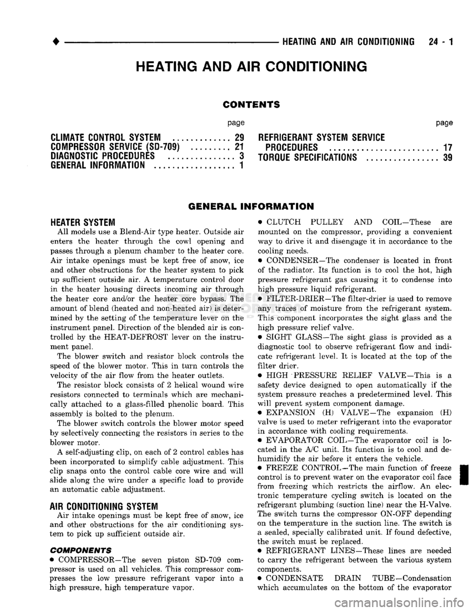
HEATER SYSTEM
All models use a Blend-Air type heater. Outside air
enters the heater through the cowl opening and
passes through a plenum chamber to the heater core. Air intake openings must be kept free of snow, ice and other obstructions for the heater system to pick
up sufficient outside air. A temperature control door
in the heater housing directs incoming air through
the heater core and/or the heater core bypass. The amount of blend (heated and non-heated air) is deter
mined by the setting of the temperature lever on the
instrument panel. Direction of the blended air is con
trolled by the HEAT-DEFROST lever on the instru ment panel. The blower switch and resistor block controls the
speed of the blower motor. This in turn controls the
velocity of the air flow from the heater outlets. The resistor block consists of 2 helical wound wire
resistors connected to terminals which are mechani cally attached to a glass-filled phenolic board. This
assembly is bolted to the plenum. The blower switch controls the blower motor speed
by selectively connecting the resistors in series to the
blower motor.
A self-adjusting clip, on each of 2 control cables has
been incorporated to simplify cable adjustment. This clip snaps onto the control cable core wire and will slide along the wire under a specific load to provide
an automatic cable adjustment.
AIR
CONDITIONING
SYSTEM
Air intake openings must be kept free of snow, ice
and other obstructions for the air conditioning sys
tem to pick up sufficient outside air.
COMPONENTS
• COMPRESSOR-The seven piston SD-709 com
pressor is used on all vehicles. This compressor com
presses the low pressure refrigerant vapor into a high pressure, high temperature vapor. • CLUTCH PULLEY AND COIL-These are
mounted on the compressor, providing a convenient
way to drive it and disengage it in accordance to the cooling needs.
• CONDENSER-The condenser is located in front
of the radiator. Its function is to cool the hot, high
pressure refrigerant gas causing it to condense into
high pressure liquid refrigerant.
• FILTER-DRIER—The filter-drier is used to remove
any traces of moisture from the refrigerant system.
This component incorporates the sight glass and the
high pressure relief valve.
• SIGHT GLASS-The sight glass is provided as a
diagnostic tool to observe refrigerant flow and indi cate refrigerant level. It is located at the top of the
filter drier.
• HIGH -PRESSURE RELIEF VALVE-This is a safety device designed to open automatically if the
system pressure reaches a predetermined level. This
will prevent system component damage. • EXPANSION (H) VALVE-The expansion (H)
valve is used to meter refrigerant into the evaporator
in accordance with cooling requirements. • EVAPORATOR COIL-The evaporator coil is lo
cated in the A/C unit. Its function is to cool and de-
humidify the air before it enters the vehicle. • FREEZE CONTROL-The main function of freeze
control is to prevent water on the evaporator coil face
from freezing which restricts the airflow. An elec
tronic temperature cycling switch is located on the
refrigerant plumbing (suction line) near the H-Valve.
The switch turns the compressor ON-OFF depending
on the temperature in the suction line. The switch is a sealed, specially calibrated unit. If found defective,
the switch must be replaced. • REFRIGERANT LINES-These lines are needed
to carry the refrigerant between the various system components.
• CONDENSATE DRAIN TUBE-Condensation
which accumulates on the bottom of the evaporator
HEATING
AND AIR
CONDITIONING
Page 1444 of 1502
•
HEATING AND AIR CONDITIONING 24 - 7 AIR CONDITIONING SYSTEM
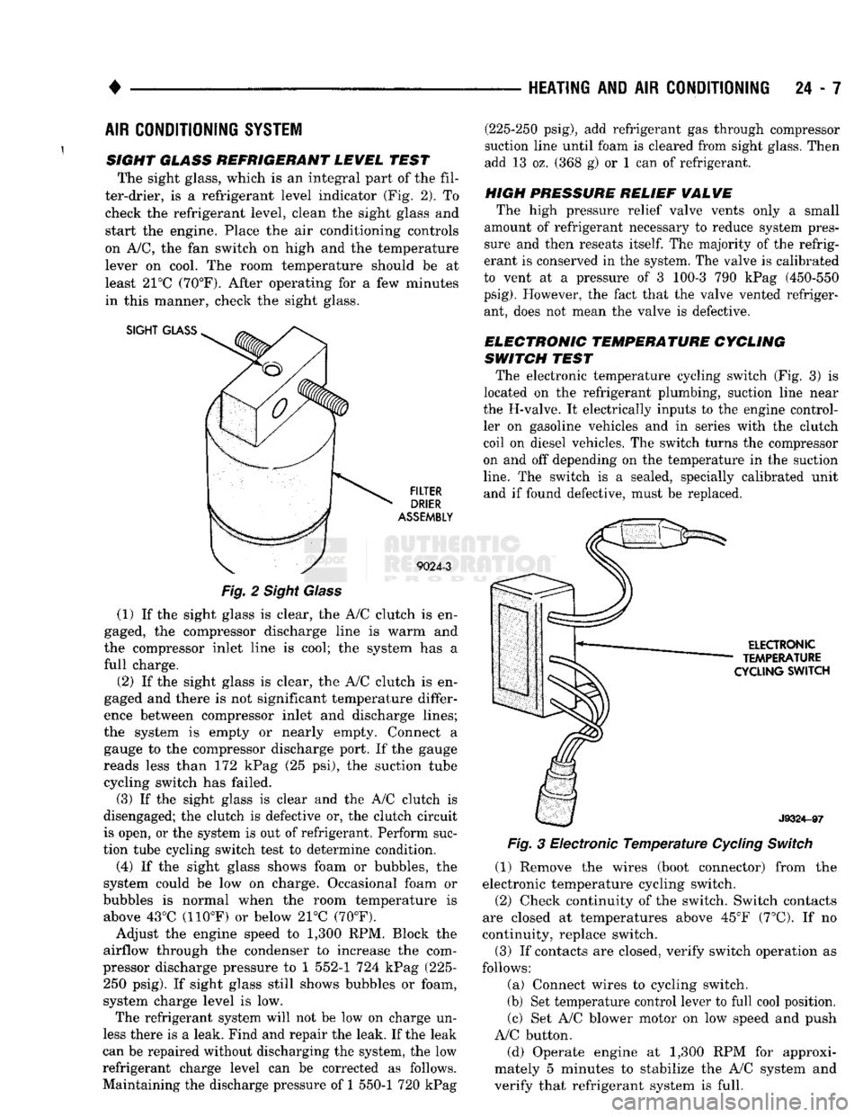
SIGHT GLASS REFRIGERANT LEWEL TEST The sight glass, which is an integral part of the fil
ter-drier, is a refrigerant level indicator (Fig. 2). To check the refrigerant level, clean the sight glass and
start the engine. Place the air conditioning controls
on A/C, the fan switch on high and the temperature lever on cool. The room temperature should be at
least 21°C (70°F). After operating for a few minutes
in this manner, check the sight glass.
SIGHT
GLASS
FILTER
DRIER
ASSEMBLY
9024-3
Fig.
2 Sight Glass
(1) If the sight glass is clear, the A/C clutch is en
gaged, the compressor discharge line is warm and
the compressor inlet line is cool; the system has a
full charge.
(2) If the sight glass is clear, the A/C clutch is en
gaged and there is not significant temperature differ
ence between compressor inlet and discharge lines;
the system is empty or nearly empty. Connect a gauge to the compressor discharge port. If the gauge
reads less than 172 kPag (25 psi), the suction tube cycling switch has failed.
(3) If the sight glass is clear and the A/C clutch is
disengaged; the clutch is defective or, the clutch circuit
is open, or the system is out of refrigerant. Perform suc
tion tube cycling switch test to determine condition.
(4) If the sight glass shows foam or bubbles, the
system could be low on charge. Occasional foam or
bubbles is normal when the room temperature is above 43°C (110°F) or below 21°C (70°F).
Adjust the engine speed to 1,300 RPM. Block the
airflow through the condenser to increase the com
pressor discharge pressure to 1 552-1 724 kPag (225- 250 psig). If sight glass still shows bubbles or foam,
system charge level is low. The refrigerant system will not be low on charge un
less there is a leak. Find and repair the leak. If the leak
can be repaired without discharging the system, the low
refrigerant charge level can be corrected as follows.
Maintaining the discharge pressure of 1 550-1 720 kPag (225-250 psig), add refrigerant gas through compressor
suction line until foam is cleared from sight glass. Then
add 13 oz. (368 g) or 1 can of refrigerant.
HIGH PRESSURE RELIEF
WALWE
The high pressure relief valve vents only a small
amount of refrigerant necessary to reduce system pres
sure and then reseats
itself.
The majority of the refrig
erant is conserved in the system. The valve is calibrated
to vent at a pressure of 3 100-3 790 kPag (450-550
psig).
However, the fact that the valve vented refriger ant, does not mean the valve is defective.
ELECTRONIC TEMPERATURE CYCLING
SWITCH TEST The electronic temperature cycling switch (Fig. 3) is
located on the refrigerant plumbing, suction line near
the H-valve. It electrically inputs to the engine control ler on gasoline vehicles and in series with the clutch
coil on diesel vehicles. The switch turns the compressor
on and off depending on the temperature in the suction
line.
The switch is a sealed, specially calibrated unit and if found defective, must be replaced.
ELECTRONIC
TEMPERATURE
CYCLING
SWITCH
J9324-97
Fig.
3 Electronic
Temperature
Cycling
Switch
(1) Remove the wires (boot connector) from the
electronic temperature cycling switch. (2) Check continuity of the switch. Switch contacts
are closed at temperatures above 45°F (7°C). If no
continuity, replace switch.
(3) If contacts are closed, verify switch operation as
follows:
(a) Connect wires to cycling switch.
(b) Set temperature control lever to full cool position. (c) Set A/C blower motor on low speed and push
A/C button.
(d) Operate engine at 1,300 RPM for approxi
mately 5 minutes to stabilize the A/C system and
verify that refrigerant system is full.