1993 DODGE TRUCK oil filter
[x] Cancel search: oil filterPage 1445 of 1502
24 - 8
HEATING
AND AIR
CONDITIONING
• (e) If compressor clutch cycles 3 to 10 times per
minute with temperature between 20°C-32°C (68°F-
90°F),
the cycling switch is normal. If the compressor
clutch fails to engage, check for continuity in the elec
trical circuit. Above 32°C (90°F) the compressor clutch
may be continuously engaged (non-cycling) due to the
high heat load. This condition is normal.
(4)
Refer to the Evaporator Heater Assembly for
the Removal/Installation procedures.
TESTING
THE
SYSTEM
FOR
LEAKS
If the air conditioning system is not cooling properly,
check that the refrigerant system is fully charged with
R-12.
Follow the procedures in the Sight Glass Refrig
erant Level Test section of this group.
If the refrigerant system is empty or low in refrig
erant charge, a leak at any of the line fittings or
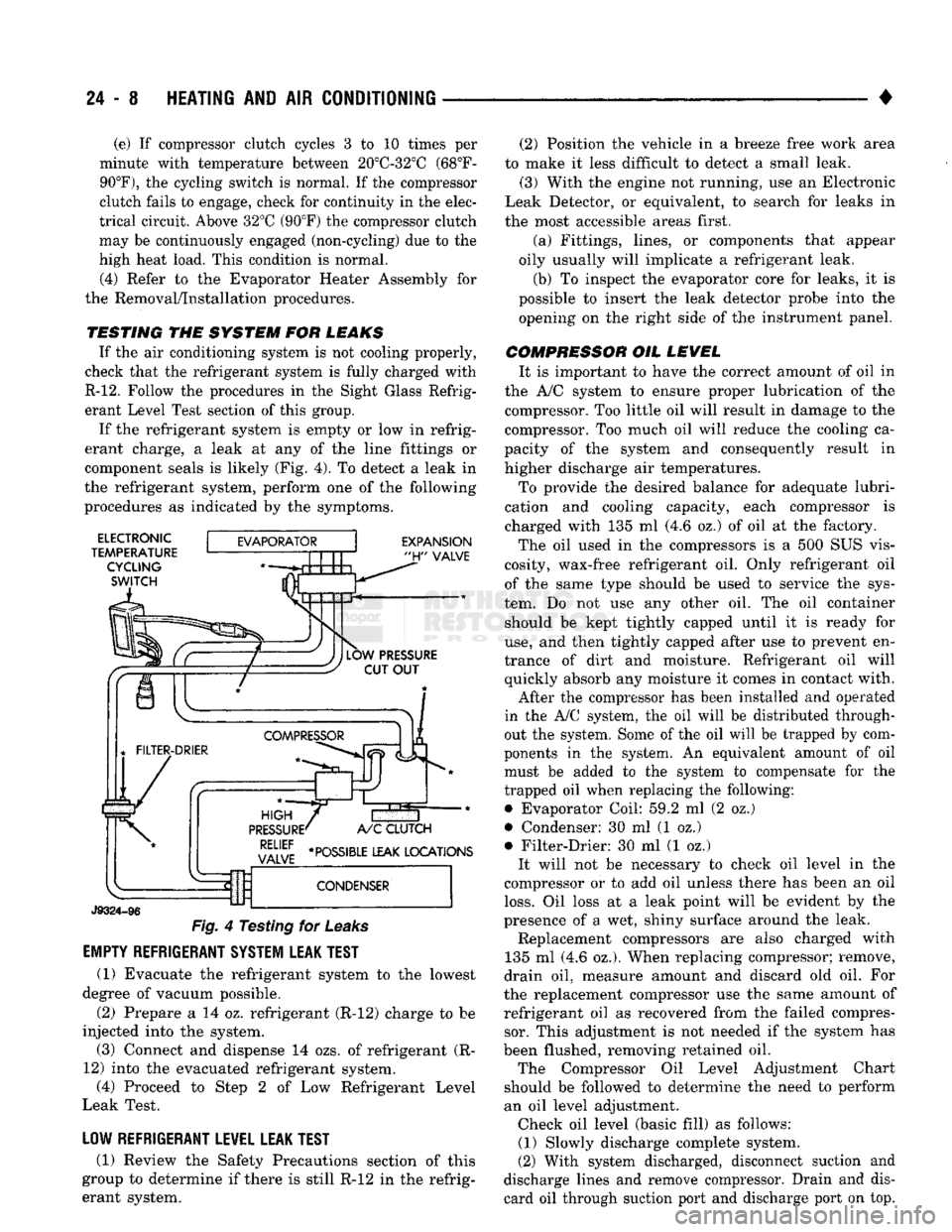
component seals is likely (Fig. 4). To detect a leak in
the refrigerant system, perform one of the following
procedures as indicated by the symptoms.
ELECTRONIC
TEMPERATURE CYCLING
SWITCH
EXPANSION
"H"
VALVE
J9324-96
Fig.
4 Testing for
Leaks
EMPTY REFRIGERANT SYSTEM LEAK TEST
(1) Evacuate the refrigerant system to the lowest
degree of vacuum possible.
(2) Prepare a 14 oz. refrigerant (R-12) charge to be
injected into the system. (3) Connect and dispense 14 ozs. of refrigerant (R-
12) into the evacuated refrigerant system, (4) Proceed to Step 2 of Low Refrigerant Level
Leak Test.
LOW REFRIGERANT LEVEL LEAK TEST
(1) Review the Safety Precautions section of this
group to determine if there is still R-12 in the refrig
erant system. (2) Position the vehicle in a breeze free work area
to make it less difficult to detect a small leak. (3) With the engine not running, use an Electronic
Leak Detector, or equivalent, to search for leaks in
the most accessible areas first.
(a) Fittings, lines, or components that appear
oily usually will implicate a refrigerant leak.
(b) To inspect the evaporator core for leaks, it is
possible to insert the leak detector probe into the opening on the right side of the instrument panel.
COMPRESSOR OIL LEVEL It is important to have the correct amount of oil in
the A/C system to ensure proper lubrication of the compressor. Too little oil will result in damage to the
compressor. Too much oil will reduce the cooling ca
pacity of the system and consequently result in
higher discharge air temperatures.
To provide the desired balance for adequate lubri
cation and cooling capacity, each compressor is
charged with 135 ml (4.6 oz.) of oil at the factory.
The oil used in the compressors is a 500 SUS vis
cosity, wax-free refrigerant oil. Only refrigerant oil of the same type should be used to service the sys
tem. Do not use any other oil. The oil container should be kept tightly capped until it is ready for
use,
and then tightly capped after use to prevent en
trance of dirt and moisture. Refrigerant oil will quickly absorb any moisture it comes in contact with.
After the compressor has been installed and operated
in the A/C system, the oil will be distributed through
out the system. Some of the oil will be trapped by com
ponents in the system. An equivalent amount of oil
must be added to the system to compensate for the
trapped oil when replacing the following: • Evaporator Coil: 59.2 ml (2 oz.)
• Condenser: 30 ml (1 oz.)
• Filter-Drier: 30 ml (1 oz.) It will not be necessary to check oil level in the
compressor or to add oil unless there has been an oil
loss.
Oil loss at a leak point will be evident by the
presence of a wet, shiny surface around the leak. Replacement compressors are also charged with
135 ml (4.6 oz.). When replacing compressor; remove,
drain oil, measure amount and discard old oil. For
the replacement compressor use the same amount of refrigerant oil as recovered from the failed compressor. This adjustment is not needed if the system has
been flushed, removing retained oil. The Compressor Oil Level Adjustment Chart
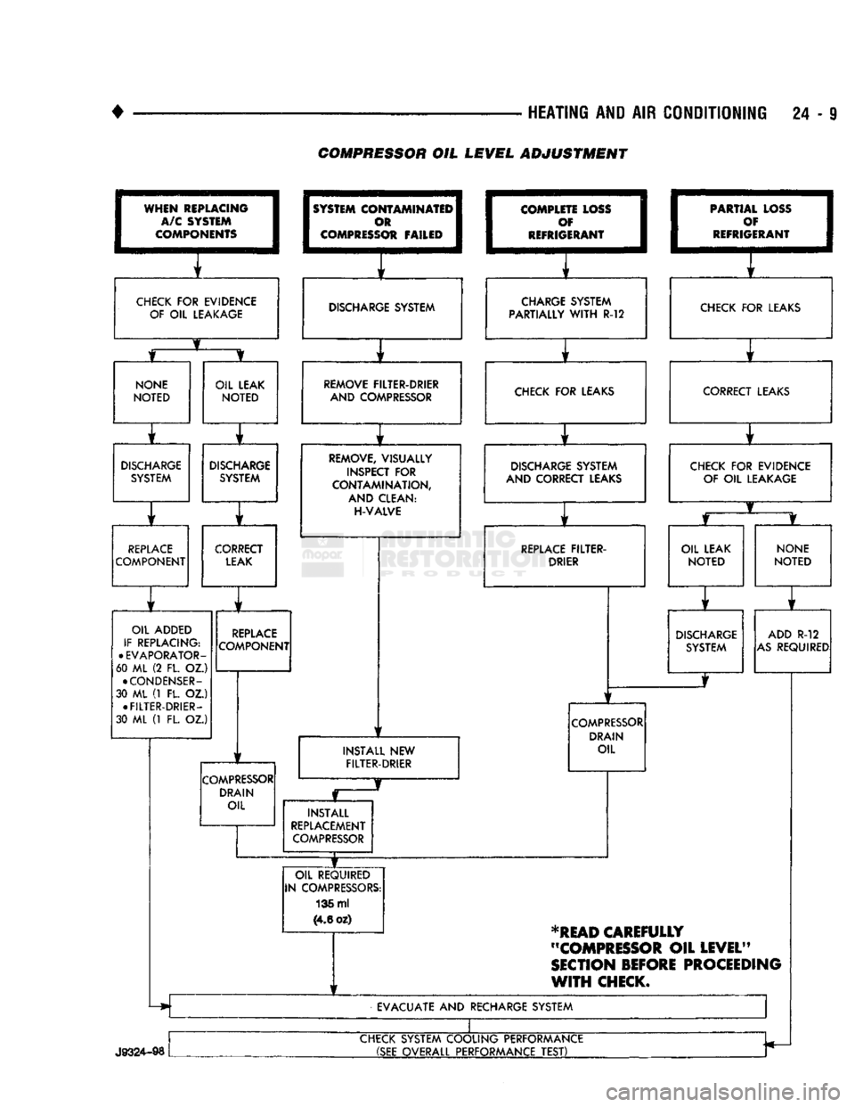
should be followed to determine the need to perform
an oil level adjustment. Check oil level (basic fill) as follows: (1) Slowly discharge complete system.
(2) With system discharged, disconnect suction and
discharge lines and remove compressor. Drain and dis card oil through suction port and discharge port on top.
Page 1446 of 1502
•
HEATING AND AIR CONDITIONING 24 - 9 COMPRESSOR OIL LEVEL ADJUSTMENT
WHEN
REPLACING
I
A/C SYSTEM
I
COMPONENTS
1
CHECK
FOR
EVIDENCE
OF
OIL
LEAKAGE
1
SYSTEM
COI
I
c
I COMPRESS
OTAMINATEI^
m 1
Ot FAILED
1
1
f
DISCHARGE SYSTEM
I
COMPLE
1
c
I
REFRIG TE LOSS
I
f 1
ERANT
1
i f
CHARGE SYSTEM
PARTIALLY
WITH
R-12 1
PARTIA
1
c
•
REFRIG L LOSS
1
)¥ I
ERANT
1
f
CHECK
FOR
LEAKS
NONE
NOTED
OIL LEAK
NOTED
r
DISCHARGE
SYSTEM
DISCHARGE
SYSTEM
r ] r
REPLACE
COMPONENT CORRECT
LEAK
OIL ADDED
IF REPLACING:
•
EVAPORATOR-
60 ML (2 FL. OZ.)
•
CONDENSER-
30 ML (1 FL. OZ.) •
FILTER-DRIER-
30 ML (1 FL. OZ.)
REPLACE
COMPONENT
COMPRESSOR
DRAIN OIL REMOVE FILTER-DRIER
AND COMPRESSOR CHECK
FOR
LEAKS
REMOVE, VISUALLY
INSPECT
FOR
CONTAMINATION,
AND CLEAN:
H-VALVE
1
1
DISCHARGE SYSTEM
AND CORRECT LEAKS
1
f
REPLACE
FILTER-
DRIER
INSTALL
NEW
FILTER-DRIER
COMPRESSOR
DRAIN OIL
INSTALL
REPLACEMENT
COMPRESSOR
OIL REQUIRED
IN COMPRESSORS: 136 ml
(4.6
oz) CORRECT LEAKS
CHECK
FOR
EVIDENCE OF
OIL
LEAKAGE
OIL LEAK
NOTED
NONE
NOTED
DISCHARGE
SYSTEM ADD
R-12
AS
REQUIRED
*READ
CAREFULLY
"COMPRESSOR
OIL
LEVEL"
SECTION
BEFORE
PROCEEDING
WITH
CHECK.
EVACUATE
AND
RECHARGE SYSTEM
J9324-98
CHECK SYSTEM COOLING PERFORMANCE
(SEE
OVERALL PERFORMANCE
TEST)
Page 1454 of 1502
•
HEATING
AND
AIR
CONDITIONING
24-17 REFRIGERANT SYSTEM SERWICE PROCEDURES
INDEX
page
Charging
the
System
19
Correcting
Low
Refrigerant
Level
.............
20
Discharging
the
System
. 19
Evacuating
the
System
19
REFRIGERANT
SAFETY
PRECAUTIONS
WARNING: EXTREME CARE MUST
BE
TAKEN
TO
PREVENT
ANY LIQUID
REFRIGERANT FROM COM
ING
IN
CONTACT
WITH
THE
SKIN
AND
ESPE
CIALLY
THE
EYES.
ALWAYS WEAR SAFETY
GOGGLES WHEN SERVICING
ANY
PART
OF
THE
REFRIGERANT SYSTEM.
IF EYE
CONTACT
IS
MADE,
APPLY
A
FEW
DROPS
OF
MINERAL
OIL
TO
THE
EYES
AND
FLUSH
WITH
WATER
FOR
SEV
ERAL MINUTES.
SEEK
MEDICAL
ATTENTION
IMME
DIATELY.
The refrigerant used
in the air
conditioner system
is Refrigerant-12 (R-12).
R-12 is
nonexplosive, non
flammable, non-corrosive,
has
practically
no
odor
and
is heavier than
air.
Although
it is
classified
as a
safe
refrigerant, certain precautions must
be
observed
to
protect
the
parts involved
and the
person
who is
working
on the
unit. Liquid
R-12, at
normal atmo sphere pressures
and
temperatures, evaporates
so
quickly that
it has the
tendency
to
freeze anything
it
contacts.
WARNING:
TO
AVOID
A
DANGEROUS EXPLOSION,
NEVER
WELD
OR
STEAM CLEAN NEAR
AIR
CON
DITIONING
LINES
OR
COMPONENTS.
DO NOT
HEAT
R-12
ABOVE
52°C (125°F)
BECAUSE
THE
CAN
MAY
EXPLODE.
The
R-12 in the
system
is
always under pressure.
Because
the
system
is
tightly sealed, heat applied
to
any part could cause this pressure
to
build
up
excessively.
WARNING: LARGE AMOUNTS
OF
REFRIGERANT
RELEASED
IN A
CLOSED WORK AREA
WILL
DIS
PLACE
THE
OXYGEN
AND
CAUSE SUFFOCATION.
ALWAYS
MAINTAIN
GOOD
VENTILATION
SUR ROUNDING
THE
WORK AREA.
R-12
gas,
under normal conditions,
is
non-poison
ous.
The
discharge
of R-12 gas
near
an
open flame
page
Pressure Gauge
and
Manifold
Assembly
18
Refrigerant
. 17
Refrigerant
Leak Repair Procedure
20
Service Precautions
. 17
can produce
a
very poisonous
gas
called phosgene.
Phosgene
is
generated when
a
flame-type leak detec
tor
is
used.
CAUTION:
When charging
an A/C
system always
keep
the
tank
in an
upright position.
If the
tank
is
on
its
side
or
upside down,
liquid
refrigerant
will
enter
the
system
and may
damage
the
compressor.
In most instances, moderate heat
is
required
to
bring
the
pressure
of the
refrigerant above system
pressure when charging
or
adding refrigerant.
A
bucket
or
large
pan of hot
water,
not
over 52°C (125°F),
is all the
heat required
for
this purpose.
Do
not heat
the
refrigerant container with
a
blow torch
or
any
other means that would raise
the
temperature and pressure above this temperature.
CAUTION:
Do not
allow
liquid
refrigerant
to
touch
bright
metal.
Refrigerant will tarnish bright metal
and
chrome
surfaces. Avoid splashing
the
refrigerant
on any
sur
face.
Refrigerant
in
combination with moisture
is
very corrosive
and can
cause extensive damage
to all
metal surfaces.
RECYCLING
(R-12) refrigerant
is a
chloroflorocarbon
(CFC)
that
can contribute
to the
depletion
of the
ozone layer
in
the upper atmosphere. Harmful radiation from
the
sun
is
filtered
out by the
ozone.
To
assist
in
protect
ing
the
ozone layer, Chrysler Corporation recom
mends that
an
(R-12) refrigerant recycling device
that meets
SAE
standard
J1991 be
used. Contact
an
automotive service equipment supplier
for
refriger
ant recycling equipment that
is
available
in
your
area. Refer
to the
operating instructions provided
with
the
recycling equipment
for
proper operation.
SERVICE
PRECAUTIONS
Kinks
in the
refrigerant tubing
or
sharp bends
in
the refrigerant hose lines will greatly reduce
the ca
pacity
of the
entire system. High pressures
are
produced
in the
system when
it is
operating. Extreme
care must
be
exercised
to
make sure that
all
connec
tions
are
pressure tight. Dirt
and
moisture
can
enter
Page 1457 of 1502
24
- 20
HEATING
AND AIR
CONDITIONING
• (3) Turn
3
refrigerant manifold valves completely
clockwise
to
puncture
the
cans
and
close
the
mani
fold valves.
(4) Purge
the air
from
the
charging line
by
loosen
ing
the
charging hose
at the
manifold gauge
set and
turn
one of the
refrigerant valves counterclockwise. When
the
refrigerant
gas
starts escaping from
the
loose connection, tighten
the
hose.
(5) Fully open
all 3
refrigerant manifold valves
and place
the
cans
of
refrigerant into
a pan
contain
ing 52°C (125°F) water.
The
water will warm
the
charging
can and aid in the
transfer
of the
charge
into
the
system.
(6) Start
the
engine
and
move
the
controls
to A/C
low blower position.
The electronic temperature cycling switch will pre
vent
the
clutch from engaging until refrigerant
is
added
to the
system.
If the
clutch does engage,
re
place
the
switch before proceeding
any
further. (7) Charge through
the
suction side
of the
system
by slowly opening
the
suction manifold valve. Adjust
the valve
as
necessary
so
charging pressure does
not
exceed
345
kPag
(50
psig). Maintain
the
temperature
of
the
water
in the pan by
adding warm water
as
necessary. (8) Adjust
the
engine speed
to a
fast idle
of
approx
imately
1,300 RPM.
(9) When
all 3
cans
of
refrigerant
are
completely
empty, close
the
manifold gauge
set
valves
and re
frigerant manifold valves. The maximum refrigerant charge
is 44 oz.
REFRIGERANT
LEAK REPAIR PROCEDURE
LOST CHARGE If
the
system
has
lost
all
charge
due to a
leak: (1) Evacuate
the
system.
(2) Charge
the
system with approximately
1
pound
of refrigerant. (3) Locate
all
leaks.
(4) Repair
all
leaks.
(5) Replace filter-drier bottle.
CAUTION:
Replacement
filter-drier
units
must
be
sealed
while
in
storage.
The
drier
used
in
these
units
absorbs
and
traps
moisture
quickly
upon
ex
posure
to the
atmosphere.
When
installing
a
drier,
have
all
tools
and
supplies ready
for
quick
reas
sembly
to
avoid keeping
the
system open
any
longer
than
necessary.
(6) Check system
oil
level. (7) Evacuate
and
charge
the
system.
LOW CHARGE If
the
system
has not
lost
all of its
refrigerant
charge; locate
and
repair
all
leaks.
If it is
necessary
to increase
the
system pressure
to
find
the
leak
(be
cause
of an
especially
low
charge),
add 230 g (1/2 lb)
of refrigerant.
If
there
has
been
a
significant
oil
loss,
check
the
system
oil
level.
If
leak repair
was
possible
without discharging system
and an oil
level check
was
not
necessary,
use
procedure
for
correcting
low
refrigerant level.
CORRECTING
LOW
REFRIGERANT LEVEL
Since
the
refrigeration system
is
completely sealed,
the refrigerant level will
not be low
unless there
is a
leak
in the
system. Before adding refrigerant where
the
cause
of a low
level
is not
known,
the
system should
be
tested
for
leaks.
Assuming that leaks have been corrected without
discharging
the
system, proceed with partial charge.
Install
and
connect manifold gauge
set.
(1) Close both manifold gauge
set
valves. Open
manifold gauge
set
needle valve.
(2) Connect
the
suction gauge test hose
to the
suc
tion service port
of the
compressor. Connect
the
dis charge gauge test hose
to the
discharge service port. (3) Connect
an end of
long test hose
to the
center
manifold outlet,
and
other
end to
refrigerant dispens ing manifold. (4) Close
the 2
dispensing manifold valves
and
open remaining dispensing manifold valve. Remove
protective
cap
from opened valve.
WARNING: NEVER
USE
THESE CANS
TO
CHARGE
INTO
THE
HIGH
PRESSURE SIDE
OF
THE
SYSTEM
(COMPRESSOR
DISCHARGE
PORT)
OR
INTO
A
SYSTEM
THAT
IS AT
HIGH
TEMPERATURE.
THE
HIGH
SYSTEM PRESSURES COULD
BE
TRANS
FERRED
INTO
THE
CHARGING
CAN
CAUSING
IT
TO EXPLODE.
(5) Screw
a can of R-12 to the
opened manifold
valve.
Be
sure gasket
is in
place
and in
good condi
tion. Tighten refrigerant
can and
manifold locking nut
to
ensure
a
good seal.
Do not
overtighten.
Tighten
to 9.5 N*m (7 ft. lbs.)
torque,
if
gasket
is in
good condition.
(6) Turn manifold valve (above
the
refrigerant
can)
completely clockwise
to
puncture
the can.
This closes
the valve
and
seals
the
refrigerant
in the can.
CAUTION:
Do not
heat refrigerant
12
above
52°C
(125°F).
(7) Place refrigerant
can in a
large
pan of
water
heated
to
52°C (125°F). Place
pan of
water containing
the refrigerant
can on an
accurate scale
so the
amount
of
refrigerant added
can be
weighed. Open
the refrigerant manifold valve.
(8) Purge
all air
from test hoses.
Air in the
system
will
be
trapped
in the
condenser causing abnormally
high discharge pressures
and
interfering with con densing
of the
refrigerant.
Page 1476 of 1502
•
HEATING AND AIR CONDITIONING 24 - 39 LOU¥ER ASSEMBLIES
REMOVAL
(1) Remove faceplate.
(2) Set faceplate with trim surface down, insert a
small screwdriver tip into the outlet housing pivot
hole.
(3)
While forcing down louver assembly pivot pin,
pull louver assembly out of rear of faceplate (Fig. 9).
INSTALLATION
(1) Position louver assembly, bottom pivot first,
into the faceplate outlet housing. The bottom pivot
pin is a smaller diameter than the top pivot pin.
(2) While deflecting the upper louver assembly
pivot pin, carefully swing the assembly into housing, so the felt pads are not damaged. Ensure top and bot
tom pivot pins are properly engaged. (3) Install faceplate.
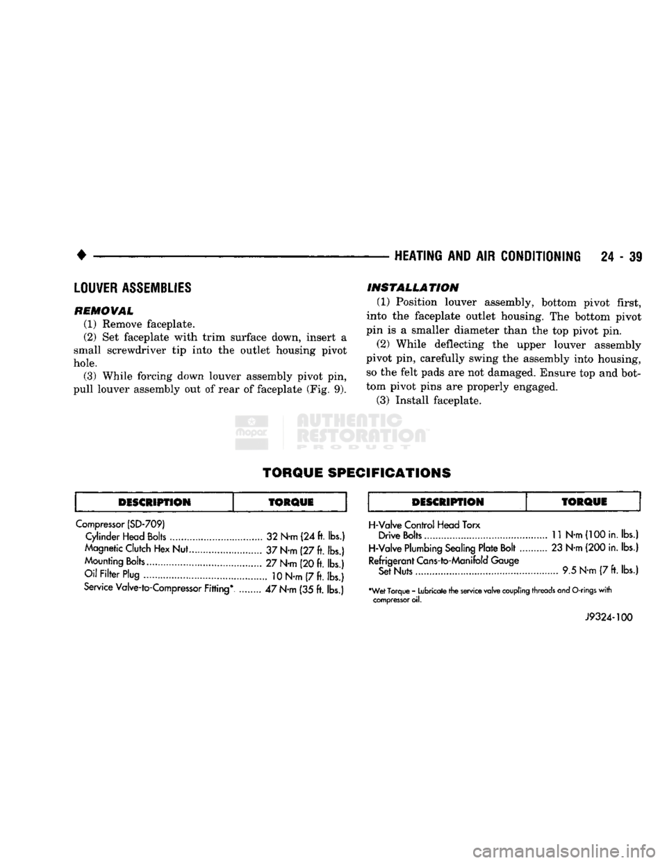
TORQUE
SPECIFICATIONS
DESCRIPTION
fORQUE
DESCRIPTION
Compressor (SD-709) Cylinder Head Bolts 32 N-m (24 ft. lbs.)
Magnetic Clutch Hex Nut... 37 N-m (27 ft. lbs.)
Mounting Bolts 27 N-m (20 ft. lbs.)
Oil Filter Plug
10
N-m (7 ft. lbs.)
Service Valve-to-Compressor Fitting* ........ 47 N-m (35 ft. lbs.)
TORQUE
H-Valve Control Head Torx Drive Bolts
11
N-m
(100
in. lbs.)
H-Valve Plumbing Sealing Plate Bolt 23 N-m (200 in. lbs.)
Refrigerant Cans-to-Manifold Gauge Set Nuts 9.5 N-m (7
ft.
lbs.)
•Wet Torque - Lubricate the service valve
coupling
threads and
O-rings
with
compressor
oil.
J9324-100
Page 1486 of 1502
•
EMISSION
CONTROL
SYSTEMS
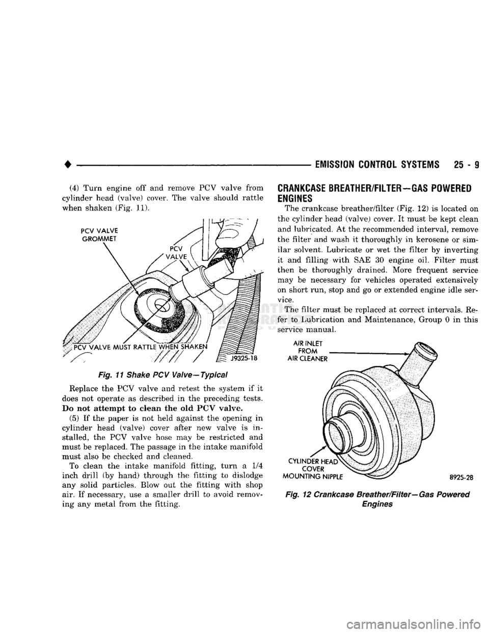
25 - 9 (4) Turn engine off and remove PCV valve from
cylinder head (valve) cover. The valve should rattle
when shaken (Fig. 11).
Fig. 11
Shake
PCV Valve-Typical
Replace the PCV valve and retest the system if it
does not operate as described in the preceding tests.
Do not attempt to clean the old PCV valve.
(5) If the paper is not held against the opening in
cylinder head (valve) cover after new valve is in stalled, the PCV valve hose may be restricted and
must be replaced. The passage in the intake manifold
must also be checked and cleaned. To clean the intake manifold fitting, turn a 1/4
inch drill (by hand) through the fitting to dislodge
any solid particles. Blow out the fitting with shop air. If necessary, use a smaller drill to avoid remov
ing any metal from the fitting.
CRANKCASE
BREATHER/FILTER-GAS POWERED
ENGINES
The crankcase breather/filter (Fig. 12) is located on
the cylinder head (valve) cover. It must be kept clean and lubricated. At the recommended interval, remove
the filter and wash it thoroughly in kerosene or sim ilar solvent. Lubricate or wet the filter by inverting
it and filling with SAE 30 engine oil. Filter must
then be thoroughly drained. More frequent service
may be necessary for vehicles operated extensively on short run, stop and go or extended engine idle ser
vice.
The filter must be replaced at correct intervals. Re
fer to Lubrication and Maintenance, Group 0 in this service manual. 8925-28
Fig. 12 Crankcase Breather/Filter—Gas Powered
Engines
Page 1496 of 1502
•
EMISSION
CONTROL SYSTEMS
25 - 19
EGR
VALVE
REMOVAL
The EGR valve and the electric EGR transducer
(EET) are serviced as one unit.
(1) Disconnect vacuum hose to EGR valve/trans
ducer assembly. Note position of hoses on EGR valve
and transducer for easier installation.
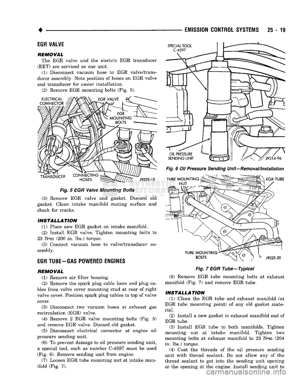
(2) Remove EGR mounting bolts (Fig. 5).
Fig.
5 EGR
Valve
Mounting
Bolts
(3) Remove EGR valve and gasket. Discard old
gasket. Clean intake manifold mating surface and
check for cracks.
INSTALLATION
(1) Place new EGR gasket on intake manifold. (2) Install EGR valve. Tighten mounting bolts to
23 N*m (200 in. lbs.) torque. (3) Connect vacuum hose to valve/transducer as
sembly.
EGR
TUBE-GAS POWERED ENGINES
REMOVAL
(1) Remove air filter housing.
(2) Remove the spark plug cable loom and plug ca
bles from valve cover mounting stud at rear of right
valve cover. Position spark plug cables to top of valve cover.
(3) Disconnect two vacuum hoses at exhaust gas
recirculation (EGR) valve. (4) Remove 2 EGR valve mounting bolts (Fig. 5)
and remove EGR valve. Discard old gasket.
(5) Disconnect electrical connector at engine oil
pressure sending unit.
(6) To prevent damage to oil pressure sending unit,
a special tool, such as number C-4597 must be used
(Fig. 6). Remove sending unit from engine.
(7) Loosen EGR tube mounting nut at intake man
ifold (Fig. 7).
Fig.
6 Oil
Pressure
Sending
Unit—Removal/Installation
Fig.
7 EGR Tube—Typical
(8) Remove EGR tube mounting bolts at exhaust
manifold (Fig. 7) and remove EGR tube.
INSTALLATION
(1) Clean the EGR tube and exhaust manifold (at
EGR tube mounting point) of any old gasket mate
rial.
(2)
Install a new gasket to exhaust manifold end of
EGR tube. (3) Install EGR tube to both manifolds. Tighten
mounting nut at intake manifold. Tighten two
mounting bolts at exhaust manifold to 23 N»m (204 in. lbs.) torque.
(4) Coat the threads of the oil pressure sending
unit with thread sealant. Do not allow any of the
thread sealant to get into the sending unit opening
or the opening at the engine. Install sending unit to