1988 PONTIAC FIERO engine oil
[x] Cancel search: engine oilPage 419 of 1825
68-8 ENGINE COOLING
However, there are limits to the tensioner's ability to
The tensioner has rovisions for a visual check to
compensate for varying lengths of belts. With the
ten- verify that it is in t e "operating range" (see Figures
sioner outside of its operating range, poor tension
608 and 609). R
control andlor damage to the tensioner may result.
ALUMINUM RADIATOR REPAIR
This radiator utilizes an aluminum core with
plastic side tanks. The core and side tanks can be
replaced separately and core repair is easily made with
the hot melt adhesive method. A transaxle oil cooler
is located in one of the side tanks. The oil cooler can
be replaced. The drain cock is located on the lower part
of one of the tanks. The drain cock is also serviceable.
Core
The core is made of aluminum and is of the
crossflow design. It utilizes large tubes that resist
plugging, and repairs to the tubes and core are easily
made using the hot melt adhesive method.
The core is attached to the tanks by clinched tabs
on the core that can be bent back if tank or core
replacement is required.
If the damage to a tube is too severe, a tube can
be blocked or plugged as explained in "Tube Blocking.
" No more than two tubes should ever be blocked on
a core. Also replace the core if more than three tabs are
broken on one side, or if two adjacent tabs are broken.
Tanks
The tanks are attached to the core by the use of
clinched tabs. The clinched tabs can be bent back if the
tanks need to be removed from the core. Bend the tabs
back only enough to remove the tank. Overbending
will weaken the tabs.
A high temperature rubber gasket is used to seal
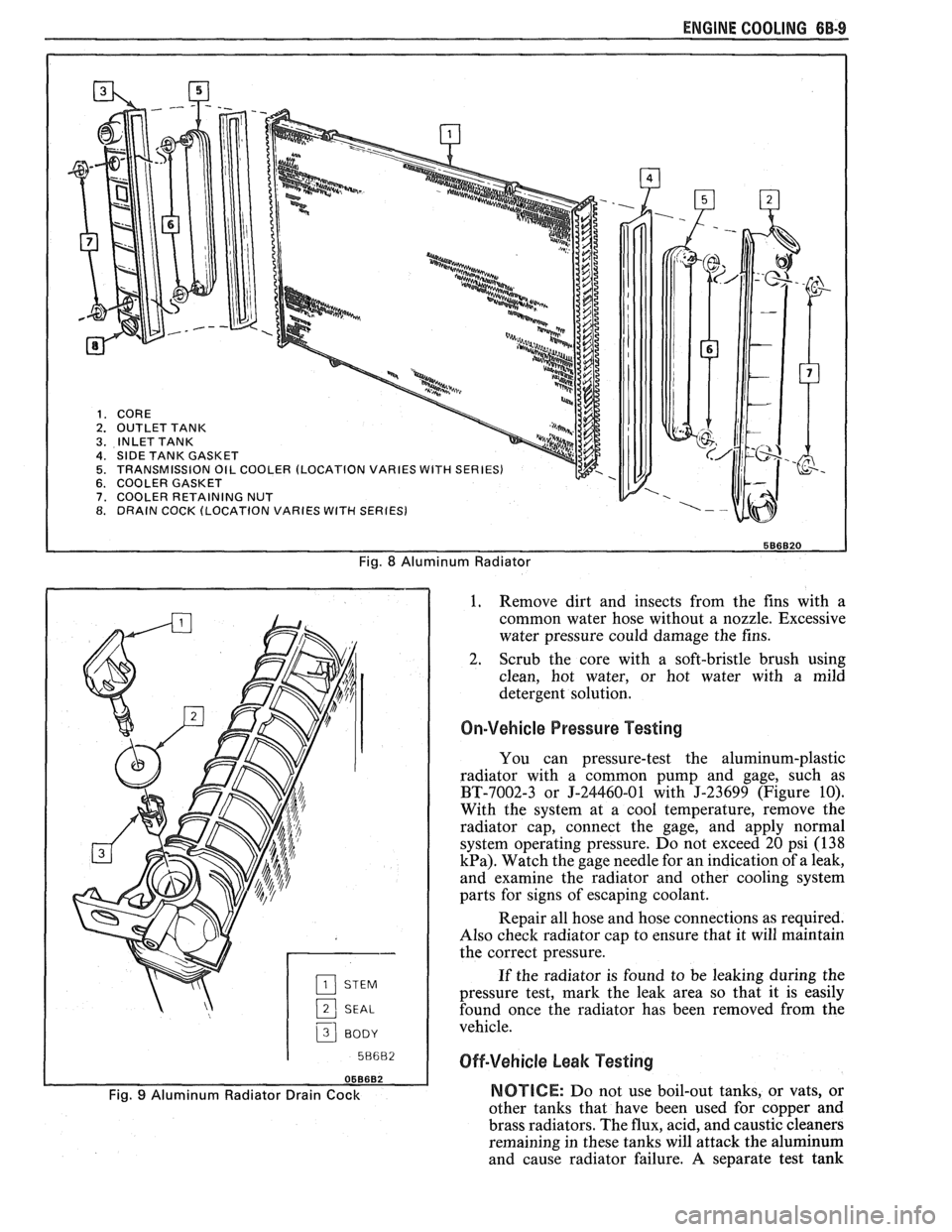
the mating surface between the core and the tank. (See
Fig. 8). The gasket must be replaced any time a tank
is removed from the core.
Transaxle Oil Cooler
The transaxle oil cooler is located in one of the
radiator side tanks. The oil cooler can be replaced by
removing the tank from the core.
A leaking oil cooler gasket can be replaced
without removing the tank from the core.
Drain Cock
The aluminum/plastic radiator utilizes a two
piece plastic drain cock and a rubber seal. The drain
cock is serviceable (See Fig.
9).
ALUMINUM RADIATOR SERVICE
The aluminum-plastic radiator can be repaired at
the dealership. The following components are easily
replaced:
e Core
e Tanks and gaskets
o Oil coolers and gaskets
e Drain cock and gasket The
tanks cannot be repaired if broken or
cracked. The radiator core can be replaced and the new
core used with the original tanks and oil cooler.
Precautions
As with all cooling system service, take measures
to prevent personal injury and damage to the system.
CAUTION: To help avoid the danger of
being burned, do not remove the
radiator cap while the engine and
radiator are
still hot. Scalding fluid
and steam can be blown out under
pressure if the
cap is taken off too
soon.
NOTICE: DO NOT USE "BOIL OUT" TANKS
OR VATS. Common service methods may
actually destroy an aluminum radiator. Caustic or
lye cleaning solutions must NOT be used for
aluminum radiators.
e Do not open the hood if you can see, or hear,
steam or coolant escaping from the engine
compartment.
e Do not remove radiator cap if radiator feels
warm.
e Do not remove the radiator cap or coolant
recovery tank cap if the coolant in the recovery
tank looks like it is boiling.
Wear eye protection.
e Wear gloves to protect your hands against
excessive heat, or the effects of chemicals on your
skin.
o Prevent dirt and water from entering the
transmission oil cooler.
e Do not use boil-out tanks, or vats, or other tanks
that have been used for copper and brass
radiators. The flux, acid, and caustic cleaners
remaining in these tanks will attack the
aluminum and cause radiator failure.
A separate
test tank containing clean water is strongly
recommended for servicing aluminum-plastic
radiators.
RIOTICE: Never use shop air that is not regulated
at
20 psi (138 kPa) to pressure test radiator.
Pressures over
20 psi (138 kPa) will damage the
radiator.
DIAGNOSIS
Leak Testing
Some core leaks can be detected by merely adding
water to the radiator. It is helpful to clean the core so
that the damaged area can be more easily found.
Page 420 of 1825
ENGINE COOLING 6B-9
Fig. 8 Aluminum Radiator
2 SEAL
3 BODY I
1. Remove
dirt and insects from the fins with a
common water hose without a nozzle. Excessive
water pressure could damage the fins.
2. Scrub the core with a soft-bristle brush using
clean, hot water, or hot water with a mild
detergent solution.
On-Vehicle Pressure Testing
You can pressure-test the aluminum-plastic
radiator with a common pump and gage, such as
BT-7002-3 or J-24460-01 with J-23699 (Figure 10).
With the system at a cool temperature, remove the
radiator cap, connect the gage, and apply normal
system operating pressure. Do not exceed 20 psi (138
kPa). Watch the gage needle for an indication of a leak,
and examine the radiator and other cooling system
parts for signs of escaping coolant.
Repair all hose and hose connections as required.
Also check radiator cap to ensure that it will maintain
the correct pressure.
If the radiator is found to be leaking during the
pressure test, mark the leak area so that it is easily
found once the radiator has been removed from the
vehicle.
Off-Vehicle beak Testing
Fig. 9 Aluminum Radiator Drain Cock NOTICE: Do not use boil-out tanks, or vats, or
other tanks that have been used for
couuer and
brass radiators. The flux, acid, and
caustiE cleaners
remaining in these tanks will attack the aluminum
and cause radiator failure. A separate test tank
Page 421 of 1825
6B-10 ENGINE COOLING
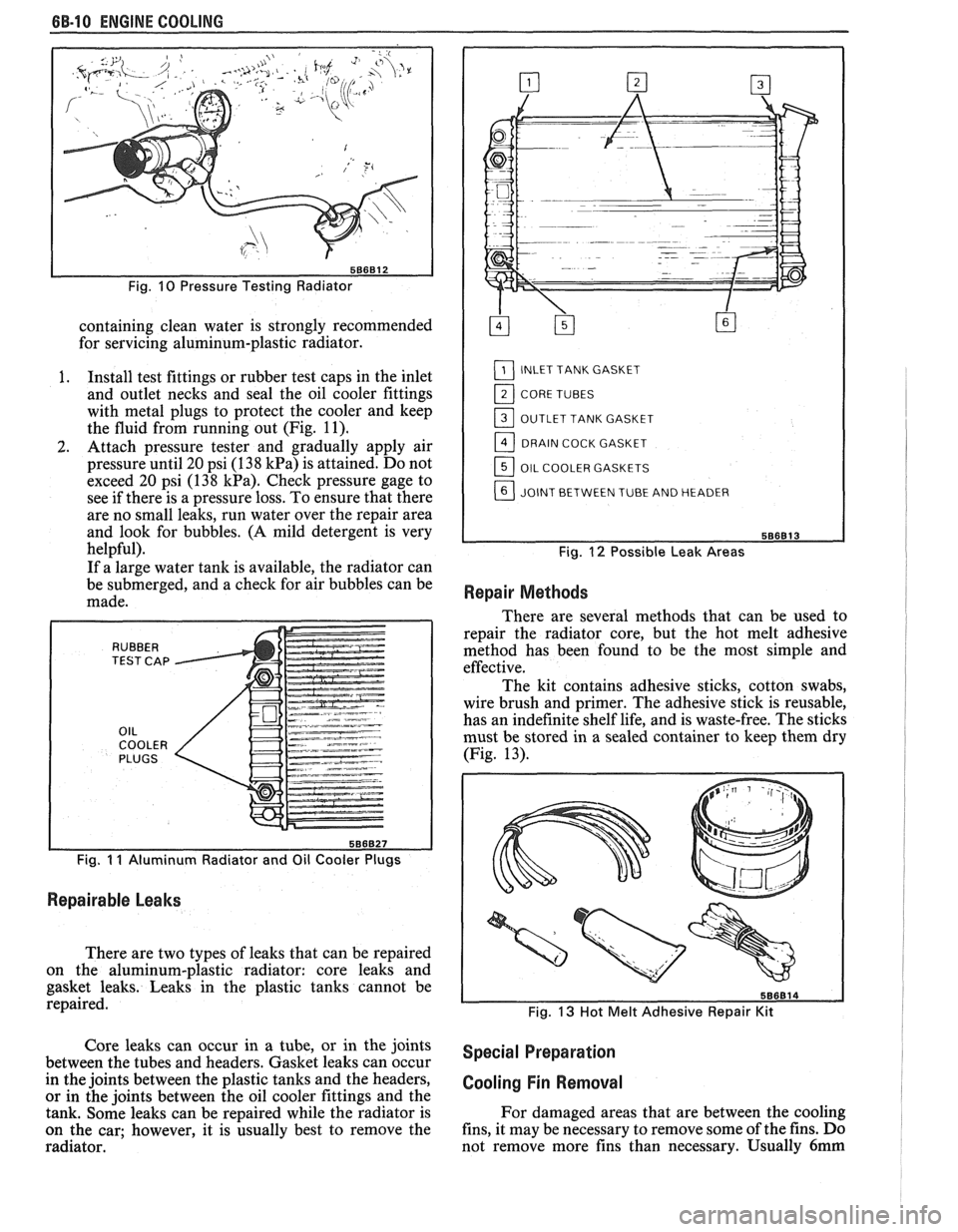
Fig. 10 Pressure Testing Radiator
containing clean water is strongly recommended
for servicing aluminum-plastic radiator.
I. Install test fittings or rubber test caps in the inlet
and outlet necks and seal the oil cooler fittings
with metal plugs to protect the cooler and keep
the fluid from running out (Fig.
11).
2. Attach pressure tester and gradually apply air
pressure until 20 psi (1
38 kPa) is attained. Do not
exceed 20 psi (138
kPa). Check pressure gage to
see if there is a pressure loss. To ensure that there
are no small leaks, run water over the repair area
and look for bubbles.
(A mild detergent is very
helpful).
If a large water tank is available, the radiator can
be submerged, and a check for air bubbles can be
made.
Fig. I I Aluminum Radiator and Oil Cooler Plugs
Repairable Leaks
There are two types of leaks that can be repaired
on the aluminum-plastic radiator: core leaks and
gasket leaks. Leaks in the plastic tanks cannot be
repaired.
L1_] INLET TANK GASKET
11_] CORE TUBES
OUTLET TANK GASKET
DRAIN COCK GASKET
OIL COOLER GASKETS
JOINT BETWEEN TUBE AND HEADER
Fig. 12 Possible Leak Areas
Repair Methods
There are several methods that can be used to
repair the radiator core, but the hot melt adhesive
method has been found to be the most simple and
effective.
The kit contains adhesive sticks, cotton swabs,
wire brush and primer. The adhesive stick is reusable,
has an indefinite shelf life, and is waste-free. The sticks
must be stored in a sealed container to keep them dry
(Fig. 13).
Fig. 13 Hot Melt Adhesive Repair Kit
Core leaks can occur in a tube, or in the joints special preparation between the tubes and headers. Gasket leaks can occur
in the joints between the plastic tanks and the headers,
cooling Fin Removal or in the joints between the oil cooler fittings and the
tank. Some leaks can be repaired while the radiator is For
damaged areas that are between the cooling
on the car; however, it is usually best to remove the fins,
it may be necessary to remove some of the fins. Do
radiator. not remove more fins
than necessary. Usually
6mm
Page 424 of 1825
ENGINE COOLING 6B-13
Fig. 22 Tightening Clinch Tabs
Fig.
23 Opening Clinch Tabs
tank with your hand to dislodge the gasket. Lift
the remaining
tab(s) with pliers.
Remove and discard the gasket.
Clean the header and gasket groove of all dirt and
old rubber.
Clean the sealing edge of the plastic tank.
Examine the header gasket surface and tank
flange for evidence of leakage, and clean or repair
the surface to remove dirt, burrs, and bumps.
Remove the oil cooler, if equipped, and install it
in the new tank.
Dip or coat the new
tank gasket in engine coolant
and position it on the header surface. The coolant
helps hold the gasket in place.
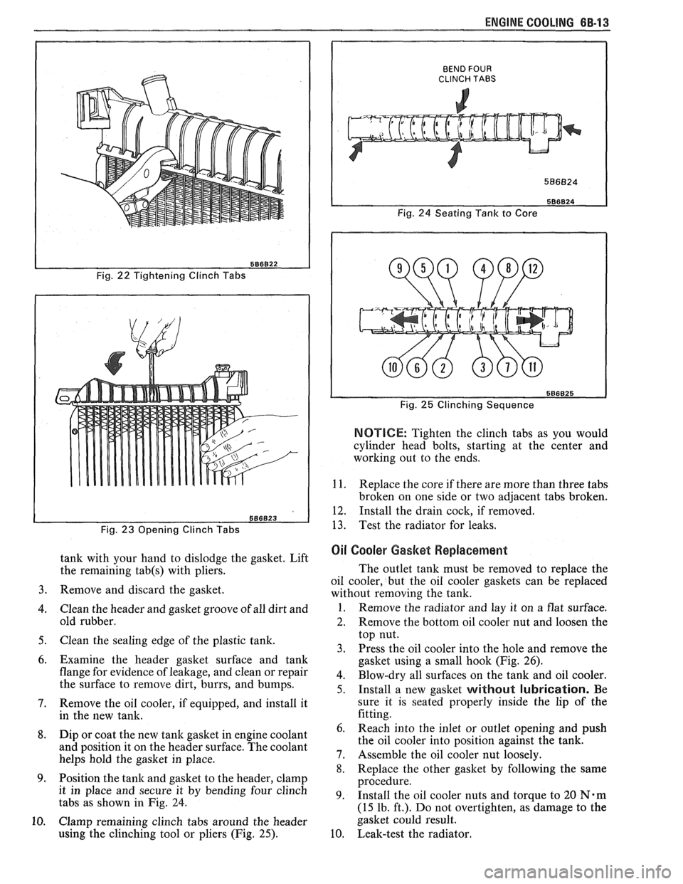
Position the tank and gasket to the header, clamp
it in place and secure it by bending four clinch
tabs as shown
in Fig. 24.
Clamp remaining clinch tabs around the header
using the clinching tool or pliers (Fig.
25).
BEND FOUR CLINCH TABS
Fig. 24 Seating Tank to Core
Fig.
25 Clinching Sequence
NOTICE: Tighten the clinch tabs as you would
cylinder head bolts, starting at the center and
working out to the ends.
1 1. Replace the core if there are more than three tabs
broken on one side or two adjacent tabs broken.
12. Install the drain cock, if removed.
13. Test the radiator for leaks.
Oil Cooler Gasket Replacement
The outlet tank must be removed to replace the
oil cooler, but the oil cooler gaskets can be replaced
without removing the tank.
1. Remove the radiator and lay it on a flat surface.
2. Remove the bottom oil cooler nut and loosen the
top nut.
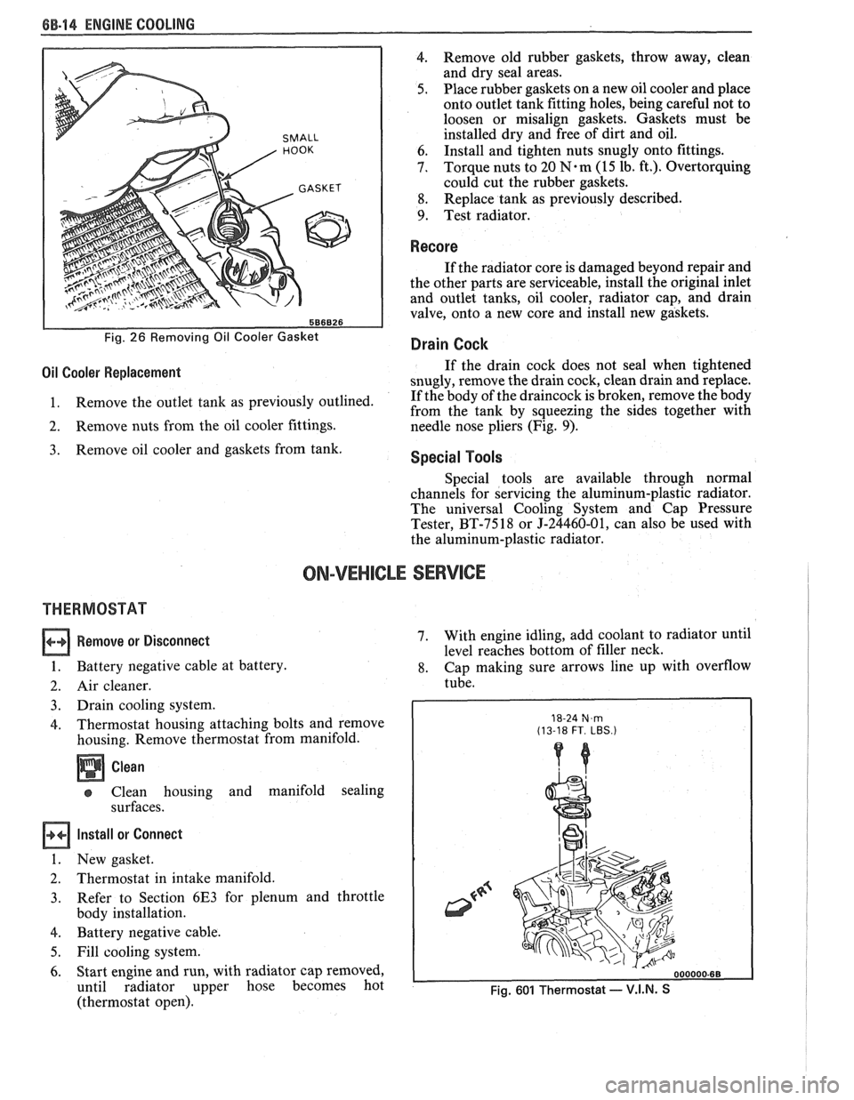
3. Press the oil cooler into the hole and remove the
gasket using a small hook (Fig. 26).
4. Blow-dry all surfaces on the tank and oil cooler.
5. Install a new gasket without lubrication. Be
sure it is seated properly inside the lip of the
fitting.
Reach into the inlet or outlet opening and push
the oil cooler into position against the tank.
Assemble the oil cooler nut loosely.
Replace the other gasket by following the same
procedure.
Install the oil cooler nuts and torque to
20 N.m
(15 lb. ft.). Do not overtighten, as damage to the
gasket could result.
Leak-test the radiator.
Page 425 of 1825
6B-I4 ENGINE COOLING
SMALL
586826
Fig. 26 Removing Oil Cooler Gasket
4. Remove old rubber gaskets, throw away, clean
and dry seal areas.
5. Place rubber gaskets on a new oil cooler and place
onto outlet tank fitting holes, being careful not to
loosen or misalign gaskets. Gaskets must be
installed dry and free of dirt and oil.
6. Install
and tighten nuts snugly onto fittings.
7. Torque nuts
to 20
N.m (15 lb. ft.). Overtorquing
could cut the rubber gaskets.
8. Replace
tank as previously described.
9. Test radiator.
Recore
If the radiator core is damaged beyond repair and
the other parts are serviceable, install the original inlet
and outlet tanks, oil cooler, radiator cap, and drain
valve, onto a new core and install new gaskets.
Drain Cock
Oil Cooler Replacement If the drain cock does not seal when tightened
snugly, remove the drain cock, clean drain and replace.
1. Remove
the outlet tank as previously outlined. If
the body of the draincock is broken, remove the body
from the tank by squeezing the sides together with
2. Remove nuts from the oil cooler fittings.
needle nose pliers (Fig. 9).
Remove oil cooler and gaskets from tank. Special Tools
Special tools are available through normal
channels for servicing the aluminum-plastic radiator.
The universal Cooling System and Cap Pressure
Tester, BT-7518 or J-24460-01, can also be used with
the aluminum-plastic radiator.
ON-VEHICLE SERVICE
THERMOSTAT
Remove or Disconnect
1. Battery negative cable at battery.
2. Air cleaner.
3. Drain cooling system.
4. Thermostat housing attaching bolts and remove
housing. Remove thermostat from manifold.
Clean
Clean housing and manifold sealing
surfaces.
Install or Connect
1. New gasket.
2. Thermostat in intake manifold.
3. Refer
to Section 6E3 for plenum and throttle
body installation.
4. Battery negative cable.
5. Fill cooling system.
6. Start engine and run, with radiator cap removed,
until radiator upper hose becomes hot
(thermostat open). 7.
With
engine idling, add coolant to radiator until
level reaches bottom of filler neck.
8. Cap making sure arrows line up with overflow
tube.
18-24 N,m (13-18 FT. LBS.)
Fig. 601 Thermostat - V.I.N. S
Page 428 of 1825
ENGINE COOLING 68.17
RADIATOR
Remove or Disconnect
1. Negative battery cable.
2. Engine coolant.
3. Fan blade. On fan clutch equipped cars, store
clutch in upright position to prevent seal leakage.
4. Upper and lower radiator hoses.
5. On vehicles equipped with automatic
transmission, plug transmission cooler lines.
6. Fan shield assembly, if applicable.
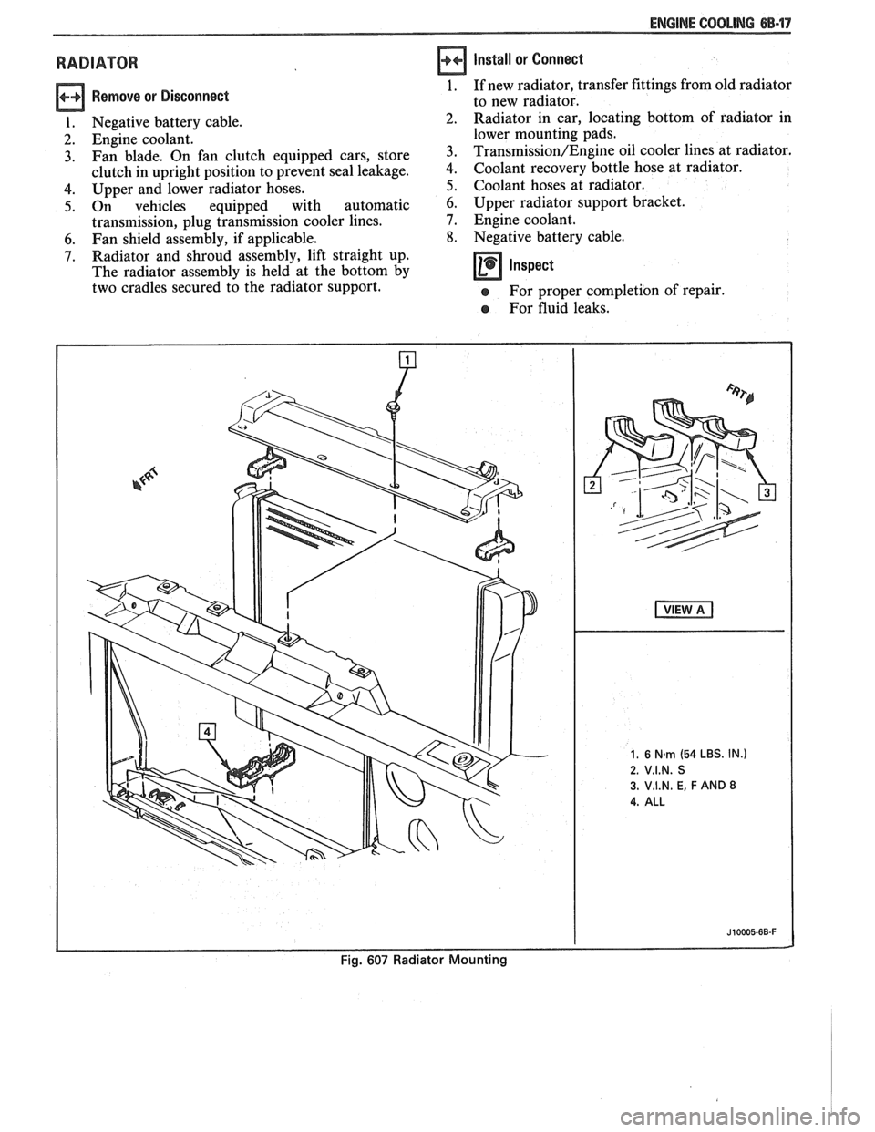
7. Radiator and shroud assembly, lift straight up.
The radiator assembly is held at the bottom by
two cradles secured to the radiator support.
Install or Connect
1. If new radiator, transfer fittings from old radiator
to new radiator.
Radiator in car, locating bottom of radiator in
lower mounting pads.
Transmission/Engine oil cooler lines at radiator.
Coolant recovery bottle hose at radiator.
Coolant hoses at radiator.
6. Upper radiator support bracket.
7. Engine coolant.
8. Negative battery cable.
Inspect -
e For proper completion of repair.
e For fluid leaks.
Page 432 of 1825
ENGINE FUEL BC-1
SECTION 6C
NE FUEL
CONTENTS
General Description ..................................... 6C-1 Fuel
Cap ........................................................... 6C-3
.................................................. ............................................. Alcohol-In-Fuel 6C- 1 Fuel Filter Neck 6C-3
................... ............ Fuel Metering .................................................. 6C-2 Fuel Gage Sending Unit .. 6C-4
....................... ............................... Throttle Body Injection (TBI) .... 6C-2 Diagnosis ,. 6C-4 ................... Service
Procedures ............................................. 6C-4
Port Fuel Injection ...................................... 6C-2
Pressure Relief ........................................... 6C-4
Fuel Feed and Return Pipe
............................... 6C-2
Flow Test .................................................... 6C-4
Fuel Pipes (MPFI)
.......................................... 6C-3
Pressure Test - TBI ................................... 6C-4
Fuel and Vapor Hoses
....................................... 6C-3
Pressure Test - MPFI .................................... 6C-4
Fuel Pump ........................................................ 6C-3 ...................................................... Fuel Pump Relay .............................................. 6C-3 Fuel Tank 6C-4
Fuel Filter
......................................................... 6C-3 Accelerator Controls ...................................... 6C-5
Fuel Tank
....................................................... 6C-3
All new General Motors vehicles are certified by
the United States Environmental Protection Agency as
conforming to the requirements of the regulations for
the control of air pollution from new motor vehicles.
This certification is contingent on certain adjustments
being set to factory standards. In most cases, these
adjustment points either have been permanently
sealed and/or made inaccessible to prevent
indiscriminate or routine adjustment in the field. For
this reason, the factory procedure for temporarily
removing plugs, caps, etc., for purposes of servicing the
product must be strictly followed and, wherever
practicable, returned to the original intent of the
design.
GENERAL DESCRIPTION
All gasoline engines are designed to use only
unleaded gasoline. Unleaded gasoline must be used for
proper emission control system operation. Its use will
also minimize spark plug fouling and extend engine oil
life. Using leaded gasoline can damage the emission
control system and could result in loss of emission
warranty coverage.
All cars are equipped with an Evaporative
Emission System. The purpose of the system is to
minimize the escape of fuel vapors to the atmosphere.
Information on this system will be found in Section
6E2, or 6E3.
When working on the fuel system, there are
several things to keep in mind.
@ Any time fuel system is being worked on,
disconnect the negative battery cable
except for those tests where battery
Adhere to all Notices and Cautions.
Always keep a dry chemical (Class B) fire
extinguisher near the work area.
-
Always use a backup wrench when loosening or
tightening a screw couple fitting.
The torque on a screw fitting is
30 N-m (22 lb.
ft.).
Pipe is used on all MPFI, TPI, SFI, and TBI
applications. Fittings require the use of an
"0"
Ring. Replace all pipe with the same type of pipe
and fittings that were removed.
All fuel pipes must meet GM Specification
124-M, or its equivalent.
All fuel hoses must meet GM Specification
6163-M, or its equivalent.
Do not replace fuel pipe with fuel hose.
voltage is required.
@ On MPFI, TPI, SF1 and TBI systems, always A1cohol-ln-Fuel
relieve the line pressure before servicing any fuel Certain driveability complaints such as
system components. hesitation, lack of power, stall, no start, etc., may be
@ Do not repair the fuel system until you have read caused
by an excessive amount of alcohol-in-fuel. The
the copy and checked the illustrations relating to complaints
may be due to fuel system corrosion and
that repair. subsequent
fuel filter plugging, deterioration of rubber
Page 452 of 1825
CRANKING SYSTEM CD2-1
CRANK NG SYSTEM
General Description ................................. 6D2-1 Service Procedures .................................. 6D2-3
Cranking System ......................... ... ........ 6D2- 1 Cranking
System ..................... .. ............. 6D2-3
Starter Motor ............................................. 6D2-1 On-Car Service ....................................... 6D2-4 Solenoid .................................................. 6D2- 1
Starter ........................... ... ...................... 6D2-4 Diagnosis ..................................................... 6D2-1 Specifications ............................................. 6D2- I I Cranking System ......................... ... ...... 6D2- 1
Unit Repair ............................................ 6D2-6- 1 1
GENERAL DESCRIPTION
The engine electrical system includes the battery, Battery: To determine the condition of the
ignition (primary and secondary), starter (and related battery,
follow the testing procedure outlined in the
wiring) and the generator (and related wiring). Battery section
(6D1).
Diagnostic charts (see Section 6D) will aid in Wiring: Inspect the wiring for damage. Inspect trouble-shooting system faults. When a fault is traced all connections to the cranking motor, solenoid, to a articular component, refer to that components' ignition switch and battery, including all ground
section of the service manual.
connections. Clean and tighten all connections, as
CRANKING SYSTEM
The cranking circuit consists of the battery,
starting motor, ignition switch, and related electrical
wiring. These components are connected electrically as
shown in Fig. 1.
Starter Motor
Wound field starter motors have pole pieces,
arranged around the armature, that are energized by
wound field coils.
Solenoid
Enclosed shift lever cranking motors have the
shift lever mechanism and the solenoid plunger
enclosed in the drive housing, protecting them from
exposure to dirt, icing conditions and splash.
In the basic circuit shown in Fig. 1, solenoid
windings are energized when the switch is closed. The
resulting plunger and shift lever movement causes the
pinion to engage the engine flywheel ring gear and the
solenoid main contacts to close, and cranking takes
place. When the engine starts, pinion overrun protects
the armature from excessive speed until the switch is
opened, at which time the return spring causes the
pinion to disengage. To prevent excessive overrun, the
switch should open immediately when the engine
starts.
DIAGNOSIS
CRANKING SYSTEM
Before removing any unit in a cranking circuit for
repair, the following checks should be made:
Electrical System General Diagnosis:
Follow the procedures shown in Section 6D to isolate
problem. required.
Solenoid
and Ignition Switch: Inspect all
switches to determine their condition.
Starter Motor Noise: To correct starter motor
noise during starting, use the following procedure:
1. Refer to Fig. 2 to determine the problem.
2. If the complaint is noise, correction can be
achieved by proper "shimming" as follows:
a. Check
flywheel for damage
- bent flywheel,
unusual wear, etc.
b. Start
engine and carefully touch outside
diameter of rotating flywheel ring gear with
chalk or crayon to show high point of tooth
runout. Turn engine off and rotate flywheel
so that the marked teeth are in the area of
the starter pinion gear.
c. Disconnect negative battery cable to
prevent cranking of engine.
d. Check pinion to flywheel clearance, as
shown in Fig. 3, by using a wire gage of
.5mm (.02OU) minimum thickness (or
diameter). Center a pinion tooth between
two flywheel teeth and gage, as shown in
Fig. 3. Do not gage in the corners, where a
misleading larger dimension may be
observed. If the clearance is under this
minimum, shimming the starter away from
the flywheel is required.
e. If
the clearance is grossly over
.5mm (.02OU)
in the vicinity of 1.5mm (.06OU) or more,
shimming the starter toward the flywheel is
required. (This is generally the problem
causing broken flywheel teeth or starter
housings.) Shimming the starter toward the
flywheel can be accomplished by shimming
only the outboard starter mounting pad.
A
shim of .4mm (.015") thickness, at this