1988 PONTIAC FIERO distributor
[x] Cancel search: distributorPage 16 of 1825

- -
GENERAL INFORMATION OA-13
LIST OF AUTOMOTIVE ABBREVIATIONS
WHICH MAY
BE USED IN THIS MANUAL
A-6 - Axial 6 Cyl. A C Compressor AIC - Air Conditioning
ACC - Auto'matic Climate Control
EMF
- Electromotive Force PAIR - Pulse Air Injection Reaction System
EMR - Electronic Module Retard
P B - Power Brakes
EOS - Exhaust Oxygen Sensor
PCV - Positive Crankcase Ventilation
ESC - Electronic Spark Control
PECV - Power Enrichment Control Valve
APT
- Adjustable Part Throttle
AT - Automatic Transmission
ATC - Automatic Temperature Control
ATDC
- After Top Dead Center
FMVSS
- Federal Motor Vehicle Safety BAR0 - Barometric Absolute Pressure Sensor
Ft. Lb. - Foot Pounds (Torque)
Bat. + - Positive Terminal FWD - Front Wheel Drive
- Four Wheel Drive
BHP - Brake Horsepower 4 x 4 - Four Wheel Drive
BP - Back Pressure
BTDC - Before Top Dead Center
HD - Heavy Duty HE1 - High Energy Ignition
Cat. Conv. - Catalytic Converter
CC - Catalytic Converter
- Cubic Centimeter - Converter Clutch
CCC - Computer Command Control
HVM
- Heater-Vent-Module
IAC
- ldle Air Control CCOT - Cycling Clutch (Orifice) Tube IC - Integrated Circuit CCP - Controlled Canister Purge
ID - Identification
C.E. - Check Engine - Inside Diameter
CEAB - Cold Engine Airbleed ILC - Idle Load Compensator
CEMF - Counter Electromotive Force I/P - Instrument Panel
CID - Cubic Inch Displacement ISC - Idle Speed Control CLOOp - Closed Loop
CLCC - Closed Loop Carburetor Control km - Kilometers
CP
- Canister Purge kmiL - Kilometers Liter (mpg) Cu. In. - Cubic Inch kPa - Kilopascals
CV - Constant Velocity
Cyl.
- Cylinder(s)
L-4 - Four Cylinder In-Line (Engine)
DBB - Dual Bed Bead L-6 - Six Cylinder In-Line (Engine)
DBM - Dual Bed Monolith
LF - Left Front DEFl - Digital Electronic Fuel Injection LR - Left Rear DFI - Digital Fuel Injection
Diff. - Differential Man. Vac. - Manifold Vacuum Distr. - Distributor MAP - Manifold Absolute Pressure
EAC
- Electric Air Control Valve
EAS - Electric Air Switching Valve MPG - Miles Per Gallon
ECC - Electronic Comfort Control
MPH - Miles Per Hour
ECM - Electronic Control Module MT - Manual Transmission
N.m - Newton Metres (Torque)
Emission Control
Fig. 014-15 -- Common Abbreviations
Page 20 of 1825
F CARLINE
ITEM 10
TransmissionRransaxle Service
The manual transmission or transaxle fluid does not
require changing. (Corvette only.) Change fluid in over-
drive unit every 30,000 miles (50 000 km).
For automatic transmissions or transaxles, change
both the fluid and filter every 15,000 miles (25 000 km) if
the car is mainly driven under one or more of these
conditions:
@ In heavy city traffic where the outside temperature
regularly reaches 90°F (32°C) or higher.
@ In hilly or mountainous terrain.
@ Frequent trailer pulling.
@ Uses such as found in taxi, police car or delivery
service.
If you do not use your car under any of these condi-
tions, change both the fluid and filter every 100,000 miles
(160 000 km). See you Owner's Manual for further
details.
ITEM 11
Spark Plug Service*
Replace spark plugs with type listed in your Owner's
Manual.
ITEM 12
Spark Plug Wire Inspection*
Clean wires and inspect for burns, cracks or other dam-
age. Check the wire boot fit at distributor and at spark plugs.
Replace wires as needed.
ITEM 13
Positive Crankcase Ventilation (PCV) Valve
Inspection*
Inspect valve for proper function. Replace valve if
necessary as well as any worn, plugged or collapsed
hoses.
ITEM 14
EGR System Service*
Conduct EGR System Service as referenced in the
EGR System Chart shown in the appropriate 6E Section.
Also, refer to your GM maintenance schedule booklet for
specific applications.
ITEM 15
Air Cleaner and PCV Filter Replacement*
On 1.6 and 2.0 liter engines, replace every 50,000
miles (80 000 km). On all other engines, replace every
30,000 miles (50 000 km). Replace more often under
dusty conditions. Ask your dealer for the proper replace-
ment interval for your driving conditions.
MAINTENANCE AND LUBRICATION 08-3
ITEM 16
Engine Timing Check*
Adjust timing to underhood label specifications. If
no specifications are shown, no adjustment is needed.
ITEM 17
Fuel Tank, Cap and Lines Inspection*
Inspect fuel tank, cap and lines (including fuel rails
and injection assembly, if so equipped) for damage or
leaks. Inspect fuel cap gasket for an even filler neck
imprint or any damage. Replace parts as needed.
ITEM 18
Thermostatically Controlled Air Cleaner
Inspection*
If your car is equipped, inspect all hoses and ducts
for proper hookup. Make sure valve works properly.
OWNER INSPECTIONS AND SERVICES
Listed below are inspections and services which
should be made by either you or a qualified technician at
the intervals shown to help ensure proper safety, emission
performance and dependability of your car. Take any
problems promptly to your dealer or another qualified
technician for service advice. Whenever repairs are neces-
sary, have them completed at once. For your safety and
that of others, any safety-related parts that could have
been damaged in an accident should be inspected and all
needed repairs should be done before operating your car.
Be sure to use the proper fluids and lubricants as shown in
Figure OB-2.
WHILE OPERATING YOUR VEHICLE
Automatic transmissionltransaxle shift indi-
cator operation - Make sure the indicator points to the
gear chosen.
Horn operation - Blow the horn occasionally to
make sure it works. Check all button locations.
I
Brake system operation -- Be alert to abnormal
sounds, increased brake pedal travel or repeated pulling to
one side when braking. Also, if a brake warning light
comes on or flashes, or the anti-lock warning light (if
equipped) comes on or remains on, something may be
wrong with part of the brake system. Have it inspected and
repaired at once.
Exhaust system operation - Be alert to any
changes in the sound of the system or any smell of fumes.
These are signs the system may be leaking or overheating.
.
Have it inspected and repaired at once. Also see "Engine
Exhaust Gas Caution (Carbon Monoxide)" and "Catalytic
Converter" in your Owner's Manual.
*An Emission Control Service
Page 47 of 1825

18-4 AIR CONDITIONING
If replacement of the pressure cycling switch is
necessary, it is important to note that this may be done
without removing the refrigerant charge.
A Schrader-
type valve is located in the pressure switch fitting.
During replacement of the pressure switch, a new
oiled O-ring must be installed and the switch assem-
bled to the specified torque of
6- 13 N*m (5- 10 lb. ft.).
Power Steering Gut-OH, or Anticipate
Switch
Engine idle quality on some cars is maintained
by cutting off the compressor (switch normally
closed) when high power steering loads are imposed.
On other cars the switch (normally open) provides a
signal to the ECM to allow engine control systems to
compensate for high-power steering loads.
Wide-Open Tkroale (WOT) Compressor
Cut-Out
Switch
A switch located on the throttle corltrols of some
carburetor equipped cars opens the circuit to the com-
pressor clutch during full throttle acceleration. The
switch activates a relay that controls the compressor
clutch. During full throttle acceleration
on cars
equipped with TBI or
Em, the TPS sends a signal to
the ECM, thereby controlling the compressor clutch.
Air Conditioning Time Delay Relay
This relay on some cars controls the current to
the entire air conditioning system and provides a short
delay of air conditioning operation upon start-up.
Constant Run Relay
Engine idle quality on some cars is maintained
by a "constant run" system (constant run relay) that
eliminates compressor cycling during engine idle for a
predetermined time after the vehicle has come to rest
from road speed.
If the idle period continues for an
extended time, the
A/C system may return to a con-
ventional C.C.O.T. mode for a short time to prevent
system freeze-up. The
A/C control relay and constant
run relays are both controlled by the Electronic Con-
trol Module (ECM) which determines operating con-
ditions by evaluating input from the distributor
(engine speed), vehicle speed sensor, air sensor and
A/C compressor "on" signal.
5-PRESSURE CYCLING 8-EXPANSION TUBE
SWITCH (ORIFICE)
6-DESSICANT BAG O-LIQUID LINE
7-OIL BLEED HOLE
10-PRESSURE RELIEF
VALVE
@ ee LOW PRESSURE LIQUID HIGH PRESSURE LIQUID LOW PRESURE VAPOR HIGH PRESSURE VAPOR
Figure 2 A/C System - Typical
Page 49 of 1825
1B-6 AIR CONDlTlONlNC
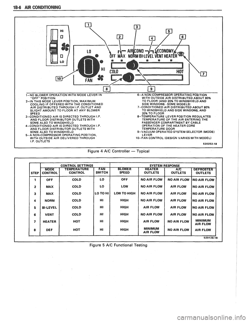
"OFF" POSITION WITH OUTSIDE AIR DISTRIBUTED ABOUT 80%
2-IN THIS MODE LEVER POSITION, MAXIMUM TO
FLOOR (AND 20% TO WINDSHIELD AND
COOLING IF OFFERED WITH THE CONDITIONED SIDE WINDOWS -SOME MODELS)
AIR DISTRIBUTED THROUGH I.P. OUTLET AND 7-CONDITIONED
AIR DISTRIBUTED ABOUT 80% SLIGHT AMOUNT TO FLOOR AT ANY BLOWER TO
WINDSHIELD AND SIDE WINDOWS, AND
20% TO FLOOR
3-CONDITIONED AIR IS DIRECTED THROUGH
I.P. 8-TEMPERATURE LEVER POSITION REGULATES
AND FLOOR DISTRIBUTOR OUTLETS WITH TEMPERATURE OF THE AIR ENTERING THE
SOME ALSO TO WINDSHIELD PASSENGER
COMPARTMENT BY CABLE
4-CONDITIONED AIR IS DIRECTED THROUGH
I.P. OPERATION OF THE HEATER CORE
AND FLOOR DISTRIBUTOR OUTLETS WITH TEMPERATURE DOOR
SOME ALSO TO WINDSHIELD 9-VACUUM
OPERATED SYSTEM SELECTOR (MODE)
5-A NON-COMPRESSOR OPERATING POSITION, LEVER
WITH OUTSIDE AIR DELIVERED THROUGH 10-FAN CONTROL
(DESIGN VARIES WITH MODEL) I.P. OUTLETS
Figure 4 AIC Controller -- Typical
Figure 5 A/C Functional Testing
Page 350 of 1825
ENGINE GENERAL INFORMATION 6-5
INSTRUMENT PANEL OIL WARNING LAMP "ON" AT IDLE
1. Oil cooler, or oil or cooler line restricted. Remove 2. Oil pump pressure low. See oil pump repair
restrictions in cooler or cooler line. procedures
in Section
6A.
ENGINE COMPRESSION EST
COMPRESSION TEST
Important
e Disconnect the "BAT." terminal from the - HE1 distributor or ignition module.
To determine if the valves or pistons are at fault,
a test should be made to determine the cylinder
compression pressure. When checking cylinder
compression, the throttle and choke should be open, all
spark plugs removed, and the battery at or near full
charge. The lowest reading cylinder should not be less
than
70% of the highest and no cylinder reading
should be less than
689 kPa (100 PSI). This
should be done with four
"puffs" per
cylinder.
Normal - Compression builds up quickly and
evenly to specified compression on each cylinder.
Piston Rings - Compression low on first
stroke, tends to build up on following strokes, but does
not reach normal. Improves considerably with addition
of oil.
Valves - Low on first stroke, does not tend to
build up on following strokes. Does not improve much
with addition of oil.
Use approximately three squirts from a plunger
type oiler.
Page 352 of 1825
2.8 LITER V-6 BA2-1
TER V-6 V N CODES RPO
CONTENTS
GENERAL DESCRIPTION ........................ 6A2- 1
ENGINE LUBRICATIONS ......................... 6A2- 1
ON-VEHICLE SERVICE ............................. 6A2-7
Powertrain Mounts .................................... 6A2-7
Rocker Arm Cover .................................... 6A2-8
Intake Manifold .......................................... 6A2-9
Exhaust Manifold ................................... 6A2-9
Rocker Arm and Push Rod ....................... 6A2- 10
Valve Mechanism
....................................... 6A2- 10
Valve Stem Oil Seal and/or Valve
Spring
.................... .. .. ... ................... 6A2- 10
Valve Lifters
............................................. 6A2- l l
Cylinder Head ............................................ 6A2- 12
Rocker Arm Studs
.................................... 6A2- 13
Valve Guides
........................................... 6A2- 13
Valve Seats
................................................ 6A2- 14
Valves
......................................................... 6A2- 14
Torsional Damper
..................................... 6A2- 14 Crankcase
Front Cover
.............................. 6A2- 15
Oil Seal (Front Cover)
........................... .... 6A2- 15
Timing Chain
& Sprocket .......................... 6A2- 15
Camshaft
................................................... 6A2- 16
Camshaft Bearings
................................... 6A2- 16
Oil Pan
........................................................ 6A2- 17
Oil Pump
.................................................. 6A2- 18
Connecting Rod Bearings .......................... 6A2- 18
Main Bearings
............................................ 6A2- 19
Oil Seal (Rear Main)
.................................. 6A2-2 1
Pistons, Rings & Connecting Rods ........... 6A2-2 1
Honing or Reboring Cylinders .................. 6A2-23
Fitting Pistons ............................................ 6A2-24
.............................................. Piston Rings 6A2-24
Engine Assembly ...................................... 6A2-25
.................................................. Crankshaft 6A2-25
........................................ Sprocket or Gear 6A2-26
..................................... SPECIFICATIONS 6A2-26
GENERAL DESCRIPTION
CYLINDER BLOCK
The cylinder block is made of alloy cast iron and
has 6 cylinders arranged in a "V" shape with 3
cylinders in each bank. The cylinder banks are set at
a
60" angle from each other.
The right bank cylinders are
1, 3, 5. Cylinders 2,
4, 6 are on the left bank.
Four main bearings support the crankshaft which
is retained by bearing caps that are machined with the
block for proper alignment and clearances.
CYLINDER HEAD
The cast alloy iron cylinder heads have individual
intake and exhaust ports for each cylinder. Valve
guides are integral, and rocker arms are retained on
individual threaded studs.
CRANKSHAFT AND BEARINGS
The crankshaft is cast nodular iron with deep
rolled fillets on all six crankpins and two center main
journals. Four steel backed aluminum bearings are
used, with
#3 bearing being the end-thrust bearing.
CAMSHAFT AND DRIVE
sprocket is also hardened sintered iron, and is pressed
onto the nose of the crankshaft.
A rubber snubber is
used to dampen chain motion.
PISTONS AND CONNECTING RODS
The pistons are cast aluminum with steel struts
using two compression rings and one coil control ring.
The piston pin is offset
1.5mm towards the major
thrust side. This allows a gradual change in thrust
pressure against the cylinder wall as the piston travels
its path. Pins are chromium steel and have a floating
fit in the pistons. They are retained in the connecting
rods by a press fit.
Connecting rods are made of forged steel. Full
pressure lubrication is directed to the connecting rods
by drilled oil passages from the adjacent main bearing
journal.
VALVE TRAIN
A very simple ball pivot-type train is used.
Motion is transmitted from the camshaft through the
hydraulic lifter and push rod to the rocker arm. The
rocker arm
~ivots on its ball and transmits the
camshaft
mot'ion to the valve. The rocker arm ball
locates on a stud, threaded into the head, and is
The camshaft is cast alloy iron with tapered 13. by a nut. The push rod is located by a guide
2mm wide lobes, offset from the lifters and tapered to plate held under the rocker arm stud, assuring that the
provide positive valve lifter rotation. The camshaft is arm Operates in the plane the
support& by four journals and includes a
distributor/oil pump drive gear, and fuel pump INTAKE MANIFOLD - - eccentric.
The intake manifold is a three piece cast
A
3/8" pitch chain drives the camshaft through
aluminum unit. It centrally supports a fuel rail with 6
a hardened sintered iron sprocket. The crankshaft
fuel injectors.
Page 358 of 1825
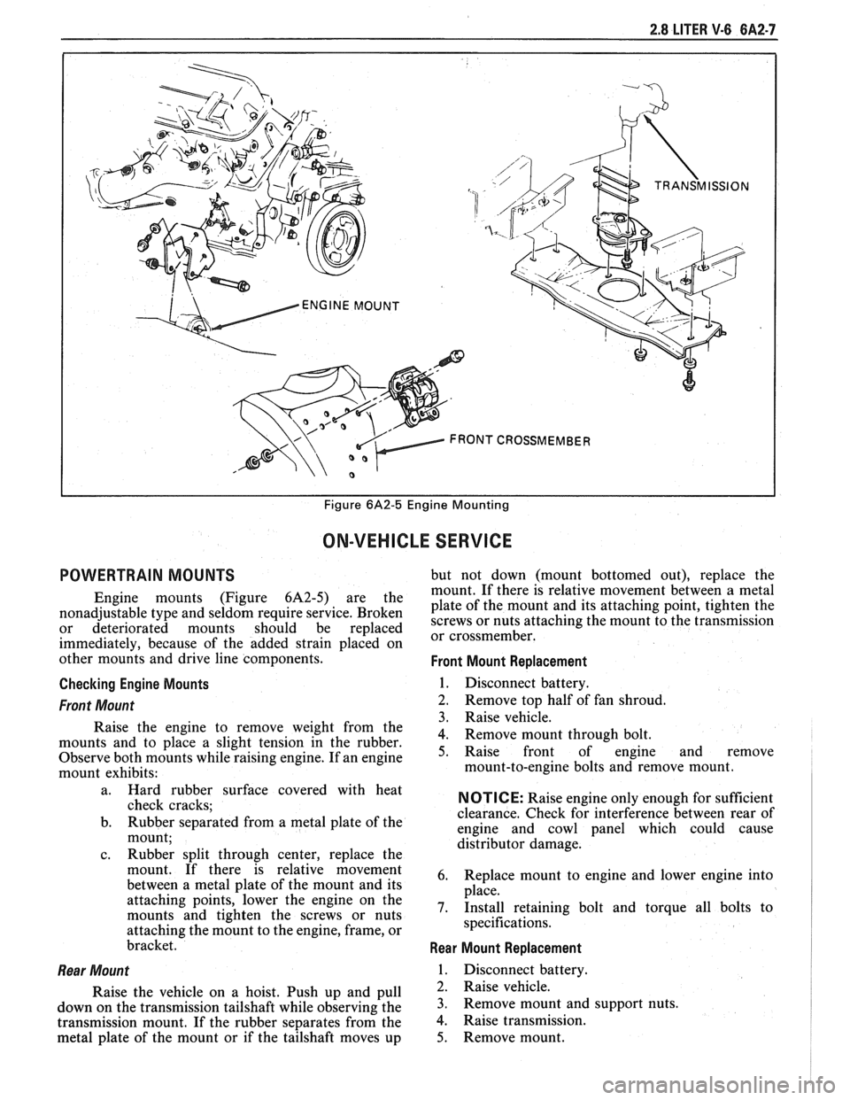
2.8 LITER V-6 6A2-7
I I Figure 6A2-5 Engine Mounting
ON-VEHICLE SERVICE
POWERTRAIN MOUNTS but not down (mount bottomed out), replace the
mount. If there is relative movement between a metal
Engine mounts (Figure 6A2-5) are the plate of the mount and its attaching point, tighten the nonadjustable type and seldom require service. Broken screws or nuts attaching the mount to the transmission or deteriorated mounts should be replaced or cross member^
immediately, because of the added strain placed on
other mounts and drive line components.
Front Mount Replacement
Checking Engine Mounts
1. Disconnect battery.
Front Mount 2. Remove top half of fan shroud.
3. Raise vehicle.
Raise the engine to remove weight from the
4. Remove mount through bolt. mounts and to place a slight tension in the rubber.
Observe both mounts while raising engine. If an engine 5. Raise front of engine and remove
mount exhibits: mount-to-engine
bolts and remove mount.
l
a. Hard rubber surface covered with heat
check cracks;
b. Rubber separated from a metal plate
of the
mount;
c. Rubber split through center, replace the
mount. If there is relative movement
between a metal plate of the mount and its
attaching points, lower the engine on the
mounts and tighten the screws or nuts
attaching the mount to the engine, frame, or
bracket.
Rear Mount
Raise the vehicle on a hoist. Push up and pull
down on the transmission tailshaft while observing the
transmission mount. If the rubber separates from the
metal plate of the mount or if the tailshaft moves up
NOTICE: Raise engine only enough for sufficient
clearance. Check for interference between rear of
engine and cowl panel which could cause
distributor damage.
6. Replace mount to engine and lower engine into
place.
7. Install retaining bolt and torque all bolts to
specifications.
Rear Mount Replacement
1. Disconnect battery.
2. Raise vehicle.
3. Remove mount and support nuts.
4. Raise transmission.
5. Remove mount.
Page 360 of 1825
2.8 LITER V-6 6A2-9
INTAKE MANIFOLD (FIGURE 6A2-7)
Removal
Disconnect battery.
Remove air cleaner.
Drain coolant.
Refer to Section 6E3 for removal of the following
PFI sub-assemblies.
e Plenum
e Fuel Rail
e Runner
Disconnect spark plug wires at spark plugs.
Disconnect wires at coil.
Remove distributor cap and spark plug wires.
Mark distributor position and remove hold down
bracket.
Remove distributor.
Remove air management hose, manual
transmission only.
Disconnect emission canister hoses. Remove pipe
bracket (front left valve cover).
Remove left valve cover.
Remove air management bracket, manual
transmission only.
Remove right valve cover.
Remove upper radiator hose.
Disconnect heater hose.
Disconnect coolant switches.
Remove manifold bolts.
Remove manifold. Discard manifold gaskets and
remove loose RTV from front and rear ridges of
cylinder case.
Installation
When installing intake gaskets, notice that the
gaskets are marked Right Side and Left Side
(carbureted only). Use them only as indicated to
maintain designed efficiency of this engine.
1. Make
sure that no oil or water is present on
surface when new RTV is applied. Place a 5mm
diameter
(3/16") bead of RTV, # 1052917 or
equivalent, on each ridge.
2. Install
new intake gaskets on cylinder heads.
Hold in place by extending ridge RTV bead up
6mm onto the gasket ends. The new intake
gaskets will have to be cut, where indicated, to
install behind push rods. Cut only those areas
that are necessary.
3. Install intake
manifold on engine. Make sure
areas between case ridges and intake are
completely sealed.
4. Install manifold retaining bolts and nuts and
torque in the sequence shown in Figure 6A2-7.
5. Install heater and radiator hose to manifold.
6. Install rocker covers as previously outlined.
7. Connect coolant switches.
8. Install air management bracket.
9. Install pipe bracket (front left rocker cover).
10. Install distributor, distributor cap and retaining
nut. Do not tighten.
11. Refer to Section 6E3 for installation of PFI
sub-assemblies removed. 12.
Connect
necessary wires and hoses.
13. Fill cooling system with
the proper mixture of
ethylene glycol anti-freeze and water. Do not
install radiator cap.
14. Start
engine, set intitial timing. After set, torque
distibutor hold down clamp bolt to 34
N-m (25
lb. ft.). Recheck timing after torquing bolt.
15. Let engine
run until radiator upper hose becomes
hot (thermostat open).
16. With
engine idling, add coolant to radiator, if
necessary, until level reaches bottom of filler
neck.
17. Install
radiator cap, making sure arrows on cap
line up with overflow tube.
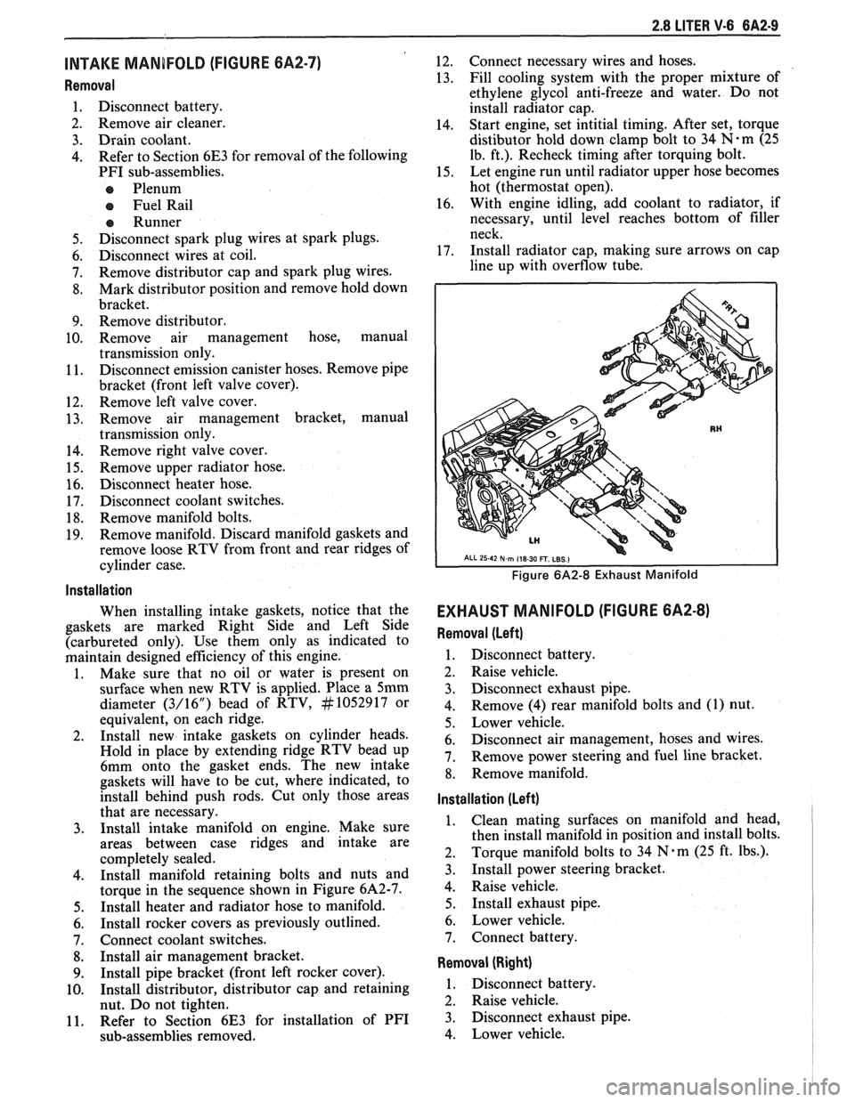
Figure 6A2-8 Exhaust Manifold
EXHAUST MANIFOLD (FIGURE 6A2-8)
Removal (Left)
1. Disconnect battery.
2. Raise vehicle.
3. Disconnect exhaust pipe.
4. Remove
(4) rear manifold bolts and (1) nut.
5. Lower vehicle.
6. Disconnect air management, hoses and wires.
7. Remove power steering and fuel line bracket.
8. Remove manifold.
Installation (Left)
1. Clean mating surfaces on manifold and head,
then install manifold in position and install bolts.
2. Torque
manifold bolts to 34
N.m (25 ft. lbs.).
3. Install power steering bracket.
4. Raise vehicle.
5. Install exhaust pipe.
6. Lower vehicle.
7. Connect battery.
Removal (Right)
1. Disconnect battery.
2. Raise vehicle.
3. Disconnect exhaust pipe.
4. Lower vehicle.