1988 PONTIAC FIERO change wheel
[x] Cancel search: change wheelPage 2 of 1825
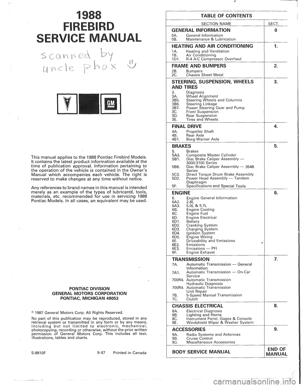
1988
SER
This manual applies to the 1988 Pontiac Firebird Models.
It contains the latest product information available at the
time of publication approval. lnformation pertaining to
the operation of the vehicle is contained in the Owner's
Manual which accompanies each vehicle. The right is
reserved to make changes at any time without notice.
Any references to brand names in this manual is intended
merely as an example of the types of
lubricant% tools,
materials, etc, recommended for use in servicing 1988
Pontiac Models. In all cases, an equivalent may be used.
PONTIAC DIVISION
GENERAL
MOTORS CORPORATION
PONTIAC, MICHIGAN 48053
1987 General Motors Corp. All Rights Reserved.
No part of this publication may be reproduced, stored in any
retrieval system or transmitted in any form or by any means,
including but not limited to electronic, mechanical,
photocopying, recording or otherwise, without the prior written
permission of General Motors Corp. This includes all text,
illustrations, tables and charts.
S-881 OF 9-87 Printed in Canada
TABLE OF CONTENTS
SECTION NAME
GENERAL INFORMATION
OA. General lnformation
OB. Maintenance & Lubrication
1 SECT.
HEATING AND AIR CONDITIONING
1A. Heating and Ventilation
1 B. Air Conditioning
1D1. R-4 AIC Com~ressor Overhaul
FRAME AND BUMPERS
2B. Bumpers 2C. Chassis Sheet Metal
STEERING, SUSPENSION, WHEELS
AND TIRES
3. Diagnosis
3A. Wheel Alignment
3B5. Steering Wheels and Columns 3B6. Steering Linkage 3B7. Power Steering Gear and Pump
3C. Front Suspension
3D. Rear Suspension
3E. Tires and Wheels
FINAL DRIVE
4A. Propeller Shaft
4B. Rear Axle
4B1. Bora-Warner Axle
BRAKES 5. Brakes 5A3. Comoosite Master Cvlinder 5B1. Disc r rake Caliper ~ssembly - 300013100 Series 5B6. Disc Brake Caliper Assembly - 3548
Series
5C3. Direct Torque Drum Brake Assembly 5D2. Power Head Assembly - Tandem Diaohraam 5F. ~~ecifications and Special Tools
ENGINE 6. Engine General lnformation 6A2. 2.8L 6A3. 5.OL & 5.7L 6B. Engine Cooling
6C. En~ine Fuel
6D. ~ngine Electrical 6D1. Battery 6D2. Cranking System 6D3. Charging System 6D4. Ignition System 6D5. Engine Wiring
6E. Driveabilitv and Emissions
6E2. ~missions' 6E3. Emissions - PFI
6F. Engine Exhaust
TRANSMISSION 7A. Automatic Transmission - General
lnformation
7A1. Automatic Transmission - On-Car
Service
700R4. Automatic Transmission Hydraulic Diagnosis
700R4. Automatic Transmission Unit Repair
76. 5-Speed Manual Transmission
7C. Clutch
CHASSIS ELECTRICAL 8A. Electrical Diagnosis
8B. Lighting and Horns
8C. Instrument
Panel, Gages
& Console
8E. Windshield Wiper &Washer System
ACCESSORIES 9A. Radio Systems and Antennas 9B. Cruise Control 9G. Miscellaneous Accessories
I BODY SERVICE MANUAL END
OF
MANUAL
Page 18 of 1825
MAINTENANCE AND LUBRICATION OB-1
SECTION OB
NTENANCE AND LUBR
CONTENTS
Maintenance Schedule, Gasoline .............................................. OB-l
Maintenance Schedules I and 11 .............................................. OB-2
Owner Inspections
......................................................... OB-3
Recommended Fluids and Lubricants ......................................... OB-6
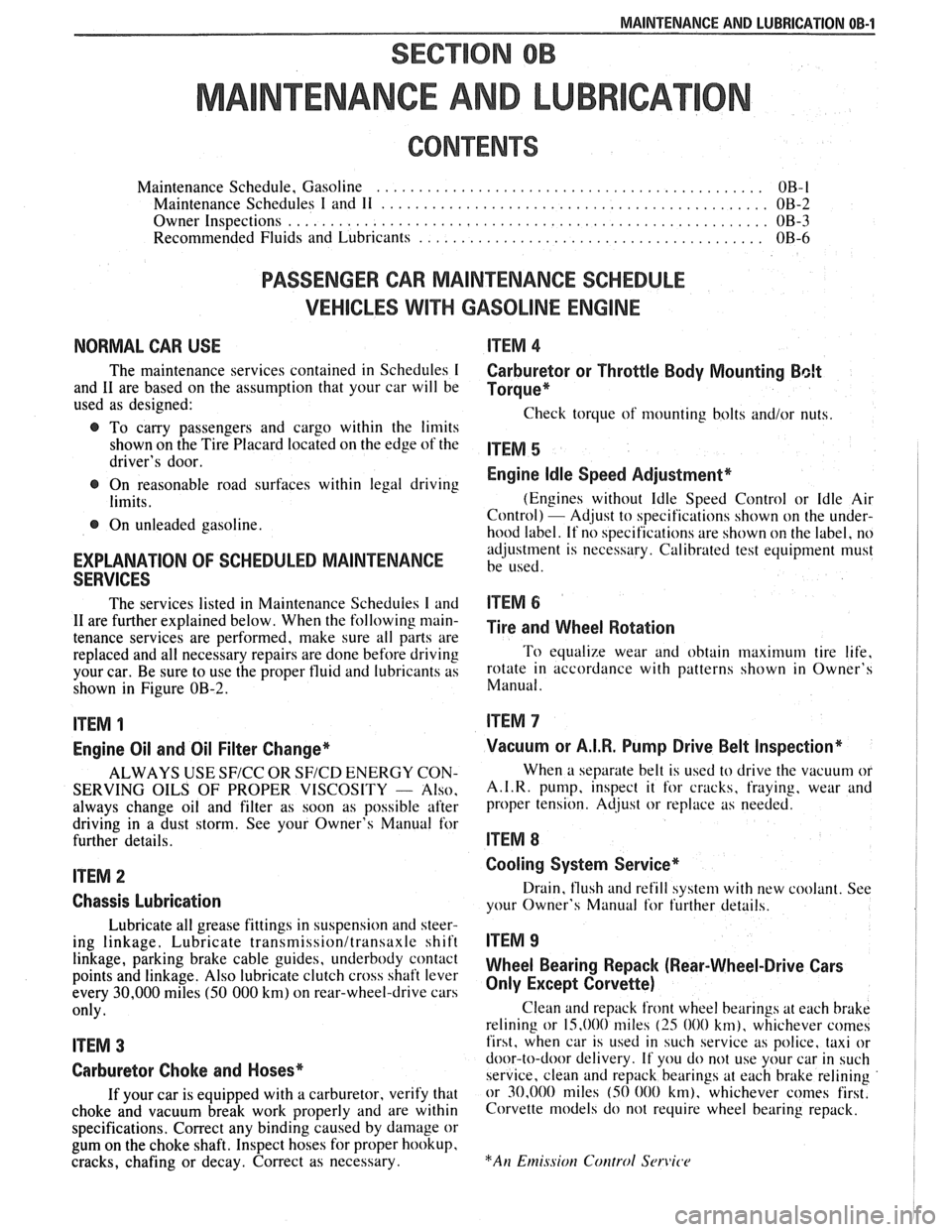
PASSENGER CAR MAINTENANCE SCHEDULE
VEHICLES
WITH GASOLINE ENGINE
NORMAL CAR USE ITEM 4
The maintenance services contained in Schedules I Carburetor or Throttle Body Mounting Bolt
and 11 are based on the assumption that your car will be Torque* used as designed:
Check torque of mounting bolts and/or nuts. @ To carry passengers and cargo within the limits
shown on the Tire Placard located on the edge of the ITEM 5 driver's door.
@ On reasonable road surfaces within legal driving Engine Idle Speed Adjustment*
limits. (Engines
without Idle Speed Control or Idle Air
Control) - Adjust to specifications shown on the under- @ On unleaded gasoline.
hood label. If no specifications are shown on the label, no
adjustment is necessary. Calibrated test equipment must
EXPLANATION OF SCHEDULED MAINTENANCE be used. SERVICES
The services listed in Maintenance Scheduies I and ITEM 6
11 are further explained below. When the following main- ~i~~ and wheel aotation tenance services are performed, make sure all parts are
replaced and all necessary repairs are done before driving To equalize wear and obtain maximum tire life,
your car. Be sure to use the proper fluid and lubricants as rotate in accordance with patterns shown in Owner's
shown in Figure OB-2. Manual.
ITEM 1
Engine Oil and Oil Filter Change*
ALWAYS USE SFICC OR SF/CD ENERGY CON-
SERVING OILS OF PROPER VISCOSITY
- Also.
always change oil and filter as soon as possible after
driving in a dust storm. See your Owner's Manual for
further details.
ITEM 2
Chassis Lubrication
Lubricate all grease fittings in suspension and steer-
ing linkage. Lubricate
transmissionltransaxle shift
linkage, parking brake cable guides, underbody contact
points and linkage. Also lubricate clutch cross shaft lever
every
30,000 miles (50 000 km) on rear-wheel-drive cars
only.
ITEM 3
Carburetor Choke and Hoses*
If your car is equipped with a carburetor, verify that
choke and vacuum break work properly and are within
specifications. Correct any binding caused by damage or
gum on the choke shaft. Inspect hoses for proper hookup,
cracks, chafing or decay. Correct as necessary.
Vacuum or A.I.R. Pump Drive Belt Inspection*
When a separate belt is used to drive the vacuum or
A.I.R.
pump, inspect it for cracks, fraying, wear and
proper tension. Adjust or replace as needed.
ITEM 8
Cooling System Service*
Drain, flush and refill system with new coolant. See
your Owner's Manual
for further details.
ITEM 9
Wheel Bearing Repack (Rear-Wheel-Drive Cars
Only Except Corvette)
Clean and repack front wheel bearings at each brake
relining or 15,000 miles
(25 000 km), whichever comes
first, when car is used in such service as police, taxi or
door-to-door delivery. If you do not use your car in such
service, clean and repack bearings at each brake relining
or 30,000 miles
(50 000 km), whichever comes first.
Corvette models do not require wheel bearing repack.
Page 21 of 1825
OB-4 MAINTENANCE AND LUBRICATION
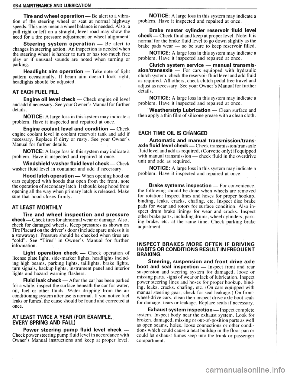
Tire and wheel operation - Be alert to a vibra-
tion of the steering wheel or seat at normal highway
speeds. This may mean a wheel balance is needed. Also, a
pull right or left on a straight, level road may show the
need for
a tire pressure adjustment or wheel alignment.
Steering system operation - Be alert to
changes in steering action. An inspection is needed when
the steering wheel is harder to turn or has too much free
play or if unusual sounds are noted when turning or
parking.
Headlight aim operation - Take note of light
pattern occasionally. If beam aim doesn't look right,
headlights should be adjusted.
AT EACH FUEL FILL
Engine oil level check - Check engine oil level
and add if necessary. See your Owner's
Manual for further
details.
NOTICE: A large loss in this system may indicate a
problem. Have it inspected and repaired at once.
Engine coolant level and condition - Check
engine coolant level in coolant reservoir tank and add if
necessary. Replace if dirty or rusty. See your Owner's
Manual for further details.
NOTICE: A large loss in this system may indicate a
problem. Have it inspected and repaired at once.
Windshield washer fluid level check -- Check
washer fluid level in container and add if necessary.
Hood latch operation - When opening hood on
cars equipped with hoods that open from the front, note
the operation of secondary latch. It should keep hood from
opening all the way when primary latch is released. Make
sure that hood closes firmly.
AT LEAST MONTI-ILY
Tire and wheel inspection and pressure
check--
Check tires for abnormal wear or damage. Also,
check for damaged wheels. Keep pressures as shown on
Tire Placard on the driver's door (include spare unless it is
a stowaway). Pressure should b\: checked when tires are
"cold". See "Tires" in Owner's Manual for further
infomation.
Light operation check - Check operation of
license plate light, side-marker lights, headlights includ-
ing high beams, parking lights, taillights, brake lights.
turn signals, backup lights, instrument panel and interior
lights and hazard warning flashers.
Fluid leak check - After the car has been parked
for a while, inspect the surface beneath the car for water,
oil, fuel or other fluids. Water dripping from the air
conditioning system after use is normal. If you notice fuel
leaks or fumes, the cause should be found and corrected at
once.
AT LEAST TWICE A YEAR (FOR EXAMPLE,
EVERY SPRING AND FALL)
Power steering pump fluid level check --
Check power steering pump fluid level in accordance with
Owner's Manual instructions and keep at proper level.
NOTICE: A large loss in this system may indicate a
problem. Have it inspected and repaired at once.
Brake master cylinder reservoir fluid level
check ---- Check fluid and keep at proper level. Note: It is
normal for the brake fluid level to go down slightly as the
brake pads wear
- so be sure to keep reservoir filled.
NOTICE: A large loss in this system may indicate a
problem. Have
it inspected and repaired at once.
Clutch system service --- manual transmis-
sionltransaxle --- For cars equipped with hydraulic
clutch system, check the reservoir fluid level and add fluid
as required. All others, check clutch pedal free travel and
adjust as necessary. See your Owner's Manual for further
details.
~
NOTICE: A large loss in this system may indicate a
problem. Have it inspected and repaired at once.
Weatherstrip Lubrication - Clean surface and
then apply a thin film of silicone grease with a clean cloth.
EACH TIME OIL IS CHANGED
Automatic and manual transmissionltrans-
axle fluid level check - Check transmission/transaxle
fluid level and add as required. (Corvette only) if equipped
with manual transmission
- check fluid in the overdrive
unit and add as required.
NOTICE: A large loss in this system may indicate a
problem. Have
it inspected and repaired at once.
Brake systems inspection - For convenience,
the following should be done when wheels are removed
for rotation: Inspect lines and hoses for proper hookup,
binding, leaks, cracks, chafing, etc. Inspect disc brake
pads for wear and rotors for surface condition. Also in-
spect drum brake linings for wear and cracks. Inspect
other brake parts, including drums, wheel cylinders, park-
ing brake, etc. at the same time. Check parking brake
adjustment.
INSPECT BRAKES MORE OFTEN IF DRIVING
HABITS OR CONDITIONS RESULT IN FREQUENT
BRAKING.
Steering, suspension and front drive axle
boot and seal inspection
- Inspect front and rear
suspension and steering system for damaged, loose or
missing parts, signs of wear or lack of lubrication. Inspect
power steering lines and hoses for proper hookup, bind-
ing, leaks, cracks, chafing, etc. (On cars equipped with
manual steering gear, check for seal leakage.) On
front-
wheel-drive cars, clean then inspect drive axle boot seals
for damage, tears or leakage. Replace seals if necessary.
Exhaust system inspection - Inspect complete
system. Inspect body near the exhaust system. Look for
broken, damaged, missing or out-of-position parts as well
as open seams, holes, loose connections or other condi-
tions which could cause a heat buildup in the tloor pan or
could let exhaust fumes seep into the trunk or passenger
compartment.
Page 131 of 1825
3-6 STEERING, SUSPENSION, TIRES AND WHEELS DIAGNOSIS
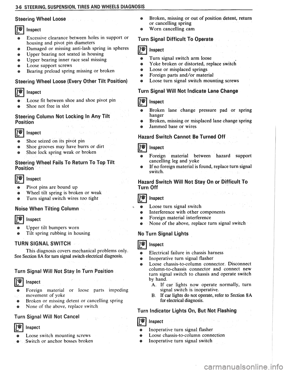
Steering Wheel Loose
lnspect
Excessive clearance between holes in support or
housing and pivot pin diameters
e Damaged or missing anti-lash spring in spheres
e Upper bearing not seated in housing
e Upper bearing inner race seal missing
e Loose support screws
e Bearing preload spring missing or broken
Steering Wheel Loose (Every Other Tilt Position)
lnspect
e Loose fit between shoe and shoe pivot pin
e Shoe not free in slot
Steering Column Not Locking In Any Tilt
Position
lnspect
e Shoe seized on its pivot pin
e Shoe grooves may have burrs or dirt
e Shoe lock spring weak or broken
Steering Wheel Fails To Return To Top Tilt
Position
Inspect
e Pivot pins are bound up
e Wheel tilt spring is broken or weak
e Turn signal switch wires too tight
Noise When Tilting Column
Inspect
e Upper tilt bumpers worn
e Tilt spring rubbing in housing
TURN SIGNAL SWITCH
This diagnosis covers mechanical problems only
See Section
8A for turn signal switch electrical diagnosis.
Turn Signal Will Not Stay In Turn Position
lnspect
e Foreign material or loose parts impeding
movement of yoke
e Broken or missing detent or cancelling spring
s None of the above, replace switch
Turn Signal Will Not Cancel
lnspect
a Loose switch mounting screws
e Switch or anchor bosses broken
e Broken, missing or out of position detent, return
or cancelling spring
Worn cancelling cam
Turn Signal Difficult To Operate
0 Inspect
e Turn signal switch arm loose
e Yoke broken or distorted, replace switch
e Loose or misplaced springs
e Foreign parts andlor material
o Loose turn signal switch mounting screws
Turn Signal Will Not Indicate Lane Change
a Inspect
e Broken lane change pressure pad or spring
hanger
e Broken, missing or misplaced lane change spring
e Jammed base or wires
Hazard Switch Cannol: Be Turned Off
a Inspect
e Foreign material between hazard support
cancelling leg and yoke
e If no foreign material is found, replace turn signal
switch.
Hazard Switch Will Not Stay On or Difficult To
Turn Off
e Loose turn signal switch
a Interference with other components
e Foreign material interference
e None of the above, replace turn signal switch
No Turn Signal Lights
lnspect
e Electrical failure in chassis harness
e Inoperative turn signal flasher
e Loose chassis-to-column connector. Disconnect
column-to-chassis connector and connect new
turn signal switch to chassis and operate switch
by hand.
A. If car lights now operate normally, turn
signal switch is inoperative.
B. If
car lights do not operate, refer to Section 8A
for electrical diagnosis.
Turn Indicator Lights On, But Not Flashing
a Inspect
e Inoperative turn signal flasher
Loose chassis-to-column connection
Inoperative turn signal switch
Page 149 of 1825
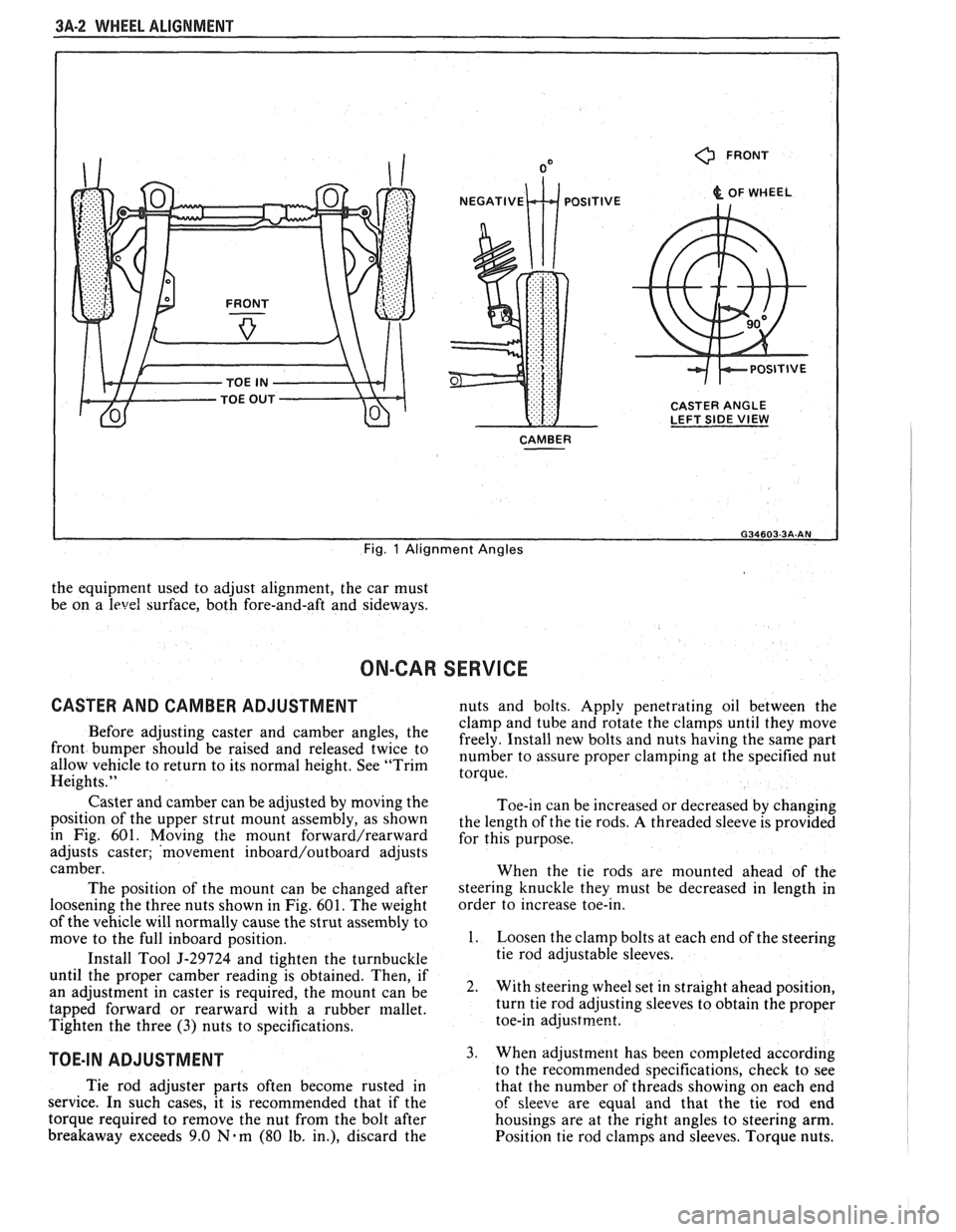
3A-2 WHEEL ALIGNMENT
0 FRONT
& OF WHEEL
CASTER ANGLE
LEFT SIDE
VIEW
CAMBER
I
Fig. 1 Alignment Angles
the equipment used to adjust alignment, the car must
be on a
level surface, both fore-and-aft and sideways.
ON-CAR SERVICE
CASTER AND CAMBER ADJUSTMENT nuts and bolts. Apply penetrating oil between the
clamp and tube and rotate the clamps until they move
Before adjusting caster and camber the freely. Install new bolts and nuts having the same part front be 'aised and twice to number to assure proper at the specified nut allow vehicle to return to its normal height. See "Trim torque. Heights."
Caster and camber can be adjusted by moving the
position of the upper strut mount assembly, as shown
in Fig. 601. Moving
the mount forward/rearward
adjusts caster; 'movement inboard/outboard adjusts
camber.
The position of the mount can be changed after
loosening the three nuts shown in Fig.
601. The weight
of the vehicle will normally cause the strut assembly to
move to the full inboard position.
Install Tool
5-29724 and tighten the turnbuckle
until the proper camber reading is obtained. Then, if
an adjustment in caster is required, the mount can be
tapped forward or rearward with a rubber mallet.
Tighten the three
(3) nuts to specifications.
TOE-IN ADJUSTMENT
Toe-in can be increased or decreased by changing
the length of the tie rods.
A threaded sleeve is provided
for this purpose.
When the tie rods are mounted ahead of the
steering knuckle they must be decreased in length in
order to increase toe-in.
1. Loosen the clamp bolts at each end of the steering
tie rod adjustable sleeves.
2. With steering wheel set in straight ahead position,
turn tie rod adjusting sleeves to obtain the proper
toe-in
adjustrne~t.
3. When adjustment has been completed according
to the recommended snecifications. check to see
Tie rod adjuster parts often become rusted in
that the number of thrkads showing on each end
service. In such cases, it is recommended that if the
of sleeve are equal and that the tie rod end
torque required to remove the nut from the bolt after housings are at the right angles to steering arm.
breakaway exceeds 9.0
Nam (80 lb. in.), discard the
Position tie rod clamps and sleeves. Torque nuts.
Page 177 of 1825
3B5-26 STEERING WHEELS AND COLUMNS
7. Lower bearing ASM (71)
8. Lower bearing adapter (70) - 9. Shaft assembly (55-58)
10. Lower shaft (58)
11. Sphere (56) from upper shaft (55) 12. Preload spring (57) from sphere (56)
13. Screws (59)
14. Housing support assembly (60) and dimmer switch rod
If%
15. i<'si release lever (63) and spring (64) 16. Hex nut (68) and hex head bolt (50)
17. Dimmer switch (67)
18. Mounting stud (49)
19. Gear shift lever bowl (65) Ignition switch (48)
and
mountin stud (49)
Preload spring (57) and sphere 156) to upper shaft (55)
Lower shaft (58) to upper shaft (55). block tooth on
shaft end of upper shaft (55) at 12 o'clock position;
notch at end of lower shaft (58) at 4 o'clock position
Shaft assembly
(55-58), lubricated with lithium grease,
to column
Column housing assembly (38) to column. Position col-
umn housing
assemby (38) and align switch actuator
rack (36) with pin on end of actuator rod (48). Pull back
on tilt release lever
(75), pushing column housing as-
sembly (38) onto column housing support assembly
(60). Release tilt release lever (75) to lock shoes
(2526) Remove tilt release lever 175) 12. Lower bearing adapter (70) '
13. Bearing, ASM (71)
In~bll or Connect 14. Retainer (72)
(Figure 2 thru 26) 15. Clip (73)
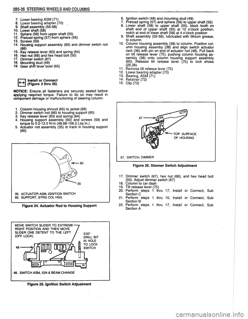
WTICE: Ensure all fasteners are securely seated before aaplying required torque. Failure to do so may result in component damage or malfunctioning of steering column.
1. Column housing shroud (65) to jacket (69)
2. Dimmer switch rod (66) to housing support (60)
3. Key release lever (63) and spring (64)
4. Housing support assembly (60) and screws (59) and
torque to
5.5-12.0 N.m (48.68-106.2 Lbs.ln.) 5. Actuator rod assembly (35) to track in housing support
(60)
35. ACTUATOR ASM, IGNITION SWITCH 60. SUPPORT, STRG COL HSG TOP
SURFACE
OF HOUSING
Figure 26. Dimmer Switch Adjustment
17. Dimmer switch (67), hex nut (68), and hex head bolt
(50). Adjust dimmer switch (67)
18. Column to car dash
19. Tilt release lever (75)
20. Perform steps 1 thru 17, Install or Connect, Sub
Section C
21. Perform steps 1 thru 10, Install or Connect, Sub
Section B
Figure 24. Actuator Rod to Housing Support 22. Perform steps 1 thru 17, Install or Connect, Sub
Section A
48. SWITCH ASM, IGN & BEAM CHANGE
Flgure 25. lgnitlon Switch Adjustment
Page 185 of 1825
385.34 STEERING WHEELS AND COLUMNS
9. Shaft assembly (55-58)
10. Lower shaft 58)
11. Sphere (56)
I rom upper shaft (55) . 12. Preload spring (57) from sphere (56)
13. Screws (59)
14. Housing support assembly (60) and dimmer switch rod
(63) 15. h& nut (65) and hex head bolt
16. Dimmer switch (64)
17. Mounting stud 18. Shroud, column housing (62)
Insbll or Connect (Flgure 2 thru 26)
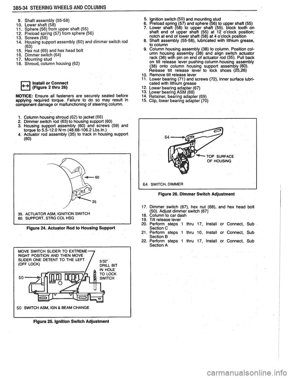
WTICE: Ensure all fasteners are securely seated before
applying required torque. Failure to do so may result in
component damage or malfunctioning of steering column.
Column housing shroud (62) to jacket (66)
Dimmer switch rod (63) to housing support (60)
Housing support assembly (60) and screws (59) and
torque to 5.5-12.0
N.m (48.68-106.2 Lbs.ln.) Actuator rod assembly (35) to track in housing support
(60)
35. ACTUATOR ASM, IGNITION SWITCH 60. SUPPORT, STRG COL HSG I
Figure 24. Actuator Rod to Housing Supporl
50 SWITCH ASM, IGN & BEAM CHANGE
5. Ignition switch (50) and mounting stud
6. Preload sprin (57) and sphere (56) to upper shaft (55)
7. Lower shaft
a58) to upper shaft (55). block tooth on
shaft end of upper shaft (55) at 12 o'clock position;
notch at end of lower shaft (58) at 4 o'clock position
8. Shaft assembly
(55-58), lubricated with lithium grease,
to column
9. Column housing assembly (38) to column. Position col-
umn housing assemby (38) and align switch actuator
rack (36) with pin on end of actuator rod (35). Pull back
on tilt release lever pushing column housing assembly
(38) onto column housing support assembly (60).
Release tilt release lever to lock shoes
(2526) 10. Remove tilt release lever 11. Lower bearing (71) and screws (72), inner surface lubri-
cated with lithium grease
12. Lower bearing adapter (67)
13. Lower bearing ASM (68)
14. Retainer, bearing adapter
(69) 15. Clip, lower bearing adapter (70)
TOP SURFACE
OF HOUSING
Figure 26. Dimmer Switch Adjustment
17. Dimmer switch
(67), hex nut (68), and hex head bolt
(50). Adjust dimmer switch (67)
18. Column to car dash
19. Tilt release lever
20. Perform
stem 1 thru 17. Install or Connect. Sub
Section C ' 21. Perform steps 1 thru 10, Install or Connect, Sub
Section B 22. .Perform steps 1 thru 17, Install or Connect, Sub
Section A
Flguro 25. lgnltion Switch Adjustment
Page 195 of 1825
387-2 POWER STEERING
The effect of improperly adjusted worm thrust
bearings or an improperly adjusted over-center preload
could cause a handling stability complaint.
To properly adjust the power steering gear, the
assembly MUST be removed from the vehicle and
adjustments performed as outlined.
For removal of the power steering gear assembly
see "Power Steering Gear".
DRIVE BELT TENSION
All drive belt tension specifications can be found
in the Engine Cooling Section 6B.
When adjusting a power steering pump belt,
never pry against the pump reservoir or pull against the
filler neck. Two systems are used for belt adjustment.
On some
models, the pump is loosened from the
bracket and moved outward to increase the tension. On
other models, a half-inch square drive hole is located
in the bracket, and this hole is used to rotate the
pump-and-bracket assembly outward to increase belt
tension.
Place belt tension gage, J-23600 or equivalent
midway between the pulleys on drive belt being
checked.
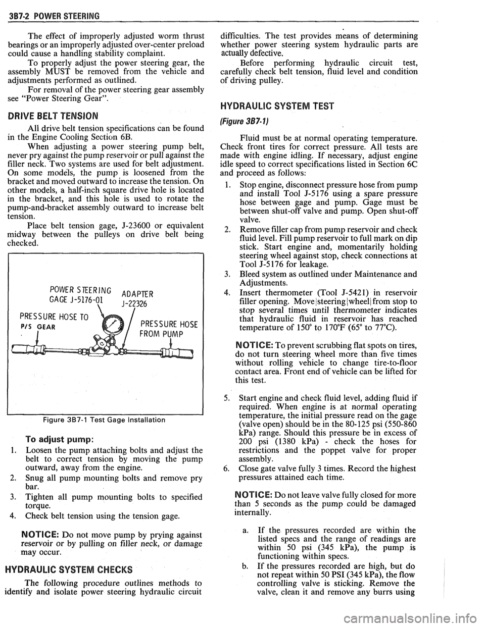
POWER SKERING ADAPER GAGE J-5176-01 J-22326
PRESSURE HOSE TO
P/S GEAR PRESSURE HOSE
Figure 387-1 Test Gage Installation
To adjust pump:
1.
Loosen the pump attaching bolts and adjust the
belt to correct tension by moving the pump
outward, away from the engine.
2. Snug all pump mounting bolts and remove pry
bar.
3. Tighten all pump mounting bolts to specified
torque.
4. Check belt tension using the tension gage.
NOTICE: Do not move pump by prying against
reservoir or by pulling on filler neck, or damage
may occur.
HYDRAULIC SYSTEM CHECKS
The following procedure outlines methods to
identify and isolate power steering hydraulic circuit difficulties.
The test provides means of determining
whether power steering system hydraulic parts are
actually
defective.
Before performing hydraulic circuit test,
carefully check belt tension, fluid level and condition
of driving pulley.
HYDRAULIC SYSTEM TEST
(Figure 387- lj
Fluid must be at normal operating temperature.
Check front tires for correct pressure. All tests are
made with engine idling. If necessary, adjust engine
idle speed to correct specifications listed in Section 6C
and proceed as follows:
1. Stop engine, disconnect pressure hose from pump
and install Tool
5-5176 using a spare pressure
hose between gage and pump. Gage must be
between shut-off valve and pump. Open shut-off
valve.
2. Remove filler cap from pump reservoir and check
fluid level. Fill pump reservoir to full mark on dip
stick. Start engine and, momentarily holding
steering wheel against stop, check connections at
Tool J-5 176 for leakage.
3. Bleed system as outlined under Maintenance and
Adjustments.
4. Insert thermometer (Tool J-5421) in reservoir
filler opening. Move
/steering (wheel/ from stop to
stop several times until thermometer indicates
that hydraulic fluid in reservoir has reached
temperature of
150" to 170°F (65" to 77°C).
N OTI G E: To prevent scrubbing flat spots on tires,
do not turn steering wheel more than five times
without rolling vehicle to change tire-to-floor
contact area. Front end of vehicle can be lifted for
this test.
5. Start engine and check fluid level, adding fluid if
required. When engine is at normal operating
temperature, the initial pressure read on the gage
(valve open) should be in the 80-125 psi (550-860
kPa) range. Should this pressure be in excess of
200 psi (1380
kPa) - check the hoses for
restrictions and the poppet valve for proper
assembly.
6. Close gate valve fully
3 times. Record the highest
pressures attained each time.
N OTI C E: Do not leave valve fully closed for more
than
5 seconds as the pump could be damaged
internally.
a. If
the pressures recorded are within the
listed specs and the range of readings are
within 50 psi (345
kPa), the pump is
functioning within specs.
b. If the pressures recorded are high, but do
not repeat within 50 PSI (345
kPa), the flow
controlling valve is sticking. Remove the
valve, clean it and remove any burrs using