1988 PONTIAC FIERO air filter
[x] Cancel search: air filterPage 18 of 1825
MAINTENANCE AND LUBRICATION OB-1
SECTION OB
NTENANCE AND LUBR
CONTENTS
Maintenance Schedule, Gasoline .............................................. OB-l
Maintenance Schedules I and 11 .............................................. OB-2
Owner Inspections
......................................................... OB-3
Recommended Fluids and Lubricants ......................................... OB-6
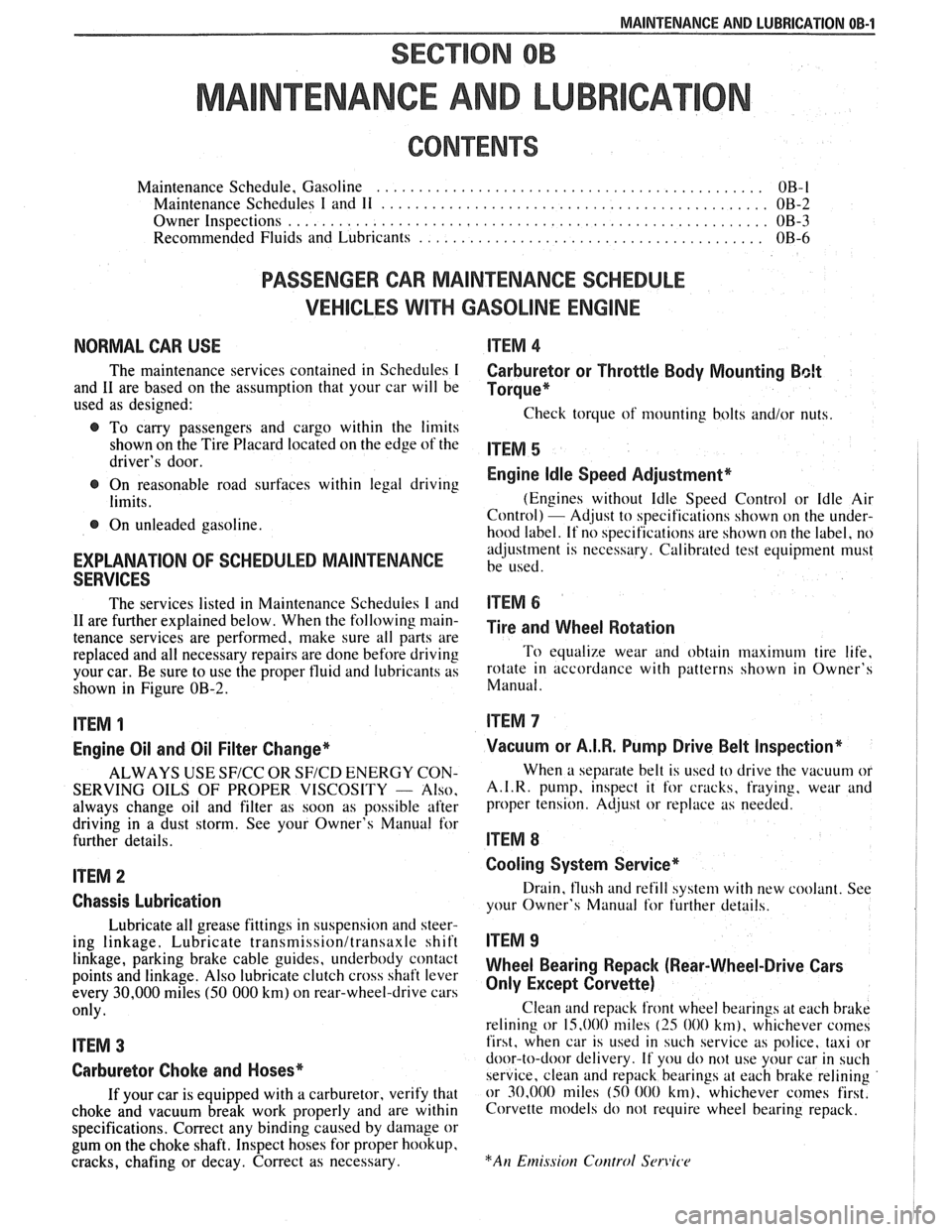
PASSENGER CAR MAINTENANCE SCHEDULE
VEHICLES
WITH GASOLINE ENGINE
NORMAL CAR USE ITEM 4
The maintenance services contained in Schedules I Carburetor or Throttle Body Mounting Bolt
and 11 are based on the assumption that your car will be Torque* used as designed:
Check torque of mounting bolts and/or nuts. @ To carry passengers and cargo within the limits
shown on the Tire Placard located on the edge of the ITEM 5 driver's door.
@ On reasonable road surfaces within legal driving Engine Idle Speed Adjustment*
limits. (Engines
without Idle Speed Control or Idle Air
Control) - Adjust to specifications shown on the under- @ On unleaded gasoline.
hood label. If no specifications are shown on the label, no
adjustment is necessary. Calibrated test equipment must
EXPLANATION OF SCHEDULED MAINTENANCE be used. SERVICES
The services listed in Maintenance Scheduies I and ITEM 6
11 are further explained below. When the following main- ~i~~ and wheel aotation tenance services are performed, make sure all parts are
replaced and all necessary repairs are done before driving To equalize wear and obtain maximum tire life,
your car. Be sure to use the proper fluid and lubricants as rotate in accordance with patterns shown in Owner's
shown in Figure OB-2. Manual.
ITEM 1
Engine Oil and Oil Filter Change*
ALWAYS USE SFICC OR SF/CD ENERGY CON-
SERVING OILS OF PROPER VISCOSITY
- Also.
always change oil and filter as soon as possible after
driving in a dust storm. See your Owner's Manual for
further details.
ITEM 2
Chassis Lubrication
Lubricate all grease fittings in suspension and steer-
ing linkage. Lubricate
transmissionltransaxle shift
linkage, parking brake cable guides, underbody contact
points and linkage. Also lubricate clutch cross shaft lever
every
30,000 miles (50 000 km) on rear-wheel-drive cars
only.
ITEM 3
Carburetor Choke and Hoses*
If your car is equipped with a carburetor, verify that
choke and vacuum break work properly and are within
specifications. Correct any binding caused by damage or
gum on the choke shaft. Inspect hoses for proper hookup,
cracks, chafing or decay. Correct as necessary.
Vacuum or A.I.R. Pump Drive Belt Inspection*
When a separate belt is used to drive the vacuum or
A.I.R.
pump, inspect it for cracks, fraying, wear and
proper tension. Adjust or replace as needed.
ITEM 8
Cooling System Service*
Drain, flush and refill system with new coolant. See
your Owner's Manual
for further details.
ITEM 9
Wheel Bearing Repack (Rear-Wheel-Drive Cars
Only Except Corvette)
Clean and repack front wheel bearings at each brake
relining or 15,000 miles
(25 000 km), whichever comes
first, when car is used in such service as police, taxi or
door-to-door delivery. If you do not use your car in such
service, clean and repack bearings at each brake relining
or 30,000 miles
(50 000 km), whichever comes first.
Corvette models do not require wheel bearing repack.
Page 20 of 1825
F CARLINE
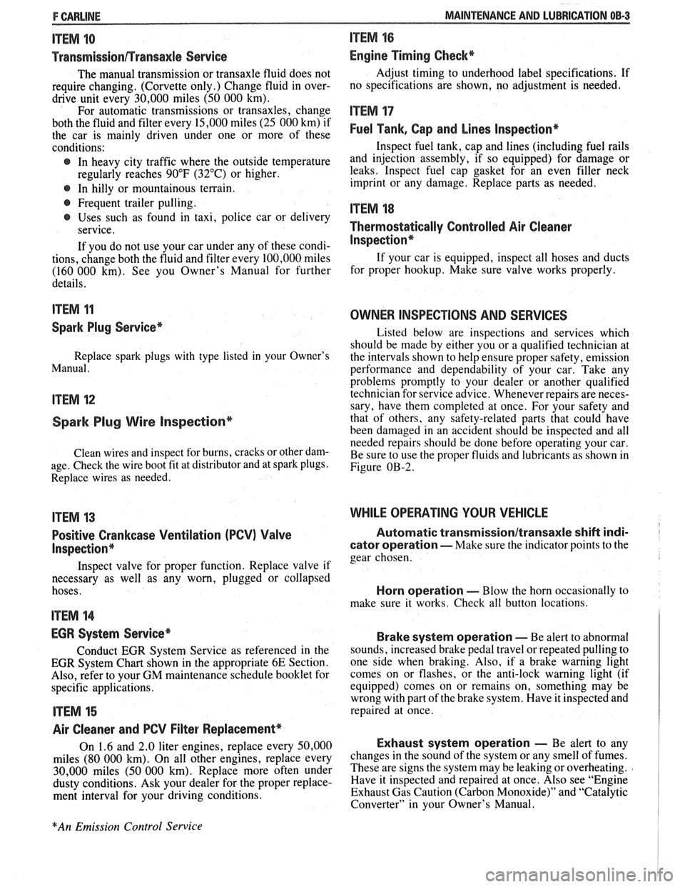
ITEM 10
TransmissionRransaxle Service
The manual transmission or transaxle fluid does not
require changing. (Corvette only.) Change fluid in over-
drive unit every 30,000 miles (50 000 km).
For automatic transmissions or transaxles, change
both the fluid and filter every 15,000 miles (25 000 km) if
the car is mainly driven under one or more of these
conditions:
@ In heavy city traffic where the outside temperature
regularly reaches 90°F (32°C) or higher.
@ In hilly or mountainous terrain.
@ Frequent trailer pulling.
@ Uses such as found in taxi, police car or delivery
service.
If you do not use your car under any of these condi-
tions, change both the fluid and filter every 100,000 miles
(160 000 km). See you Owner's Manual for further
details.
ITEM 11
Spark Plug Service*
Replace spark plugs with type listed in your Owner's
Manual.
ITEM 12
Spark Plug Wire Inspection*
Clean wires and inspect for burns, cracks or other dam-
age. Check the wire boot fit at distributor and at spark plugs.
Replace wires as needed.
ITEM 13
Positive Crankcase Ventilation (PCV) Valve
Inspection*
Inspect valve for proper function. Replace valve if
necessary as well as any worn, plugged or collapsed
hoses.
ITEM 14
EGR System Service*
Conduct EGR System Service as referenced in the
EGR System Chart shown in the appropriate 6E Section.
Also, refer to your GM maintenance schedule booklet for
specific applications.
ITEM 15
Air Cleaner and PCV Filter Replacement*
On 1.6 and 2.0 liter engines, replace every 50,000
miles (80 000 km). On all other engines, replace every
30,000 miles (50 000 km). Replace more often under
dusty conditions. Ask your dealer for the proper replace-
ment interval for your driving conditions.
MAINTENANCE AND LUBRICATION 08-3
ITEM 16
Engine Timing Check*
Adjust timing to underhood label specifications. If
no specifications are shown, no adjustment is needed.
ITEM 17
Fuel Tank, Cap and Lines Inspection*
Inspect fuel tank, cap and lines (including fuel rails
and injection assembly, if so equipped) for damage or
leaks. Inspect fuel cap gasket for an even filler neck
imprint or any damage. Replace parts as needed.
ITEM 18
Thermostatically Controlled Air Cleaner
Inspection*
If your car is equipped, inspect all hoses and ducts
for proper hookup. Make sure valve works properly.
OWNER INSPECTIONS AND SERVICES
Listed below are inspections and services which
should be made by either you or a qualified technician at
the intervals shown to help ensure proper safety, emission
performance and dependability of your car. Take any
problems promptly to your dealer or another qualified
technician for service advice. Whenever repairs are neces-
sary, have them completed at once. For your safety and
that of others, any safety-related parts that could have
been damaged in an accident should be inspected and all
needed repairs should be done before operating your car.
Be sure to use the proper fluids and lubricants as shown in
Figure OB-2.
WHILE OPERATING YOUR VEHICLE
Automatic transmissionltransaxle shift indi-
cator operation - Make sure the indicator points to the
gear chosen.
Horn operation - Blow the horn occasionally to
make sure it works. Check all button locations.
I
Brake system operation -- Be alert to abnormal
sounds, increased brake pedal travel or repeated pulling to
one side when braking. Also, if a brake warning light
comes on or flashes, or the anti-lock warning light (if
equipped) comes on or remains on, something may be
wrong with part of the brake system. Have it inspected and
repaired at once.
Exhaust system operation - Be alert to any
changes in the sound of the system or any smell of fumes.
These are signs the system may be leaking or overheating.
.
Have it inspected and repaired at once. Also see "Engine
Exhaust Gas Caution (Carbon Monoxide)" and "Catalytic
Converter" in your Owner's Manual.
*An Emission Control Service
Page 44 of 1825
AIR CONDITIONING 1B-1
SECTION 1B
R COND
When performing air conditioning diagnosis on vehicles equipped with a catalytic converter, it will be necessary to
WARM the engine to a NORMAL operating temperature BEFORE attempting to idle the engine for periods greater
than five
(5) minutes. Once the engine attains normal idle, diagnosis and adjustments can be made.
CONTENTS
.................. General Description .................................. 1B-1 Accumulator Assembly Service .1B-19
.......................... C.C.O.T. A!C System ................................ 1B-1 On-Vehicle Sewice ..... 1B-20
....................................... System Components - Functional ................. 1B-2 Blower Motor .1B-20
..................................... System Components - Control ..................... 1B-3 Hi-Blower Relay 1B-20
...................................... Relays and Switches ................................... 1B-3 Blower Resistor 1B-20
Diagnosis ................................................. 1B-5 Controller, Blower Switch or Vacuum
................................................ Testing the Refrigerant System ...................... 1B-5 Valve .lB-20
Insufficient Cooling "Quick-Check Temperature Control Cable ....................... .1B-20
.................................... Procedure.. ............................................. 1B-5 Vacuum
Harness .lB-20
C.C.O.T. A/C System Diagnostic Control Wiring Harness ........................... .1B-20
..... ................................. Procedure.. ............................................. 1B-8 Heater
Core .. .lB-21
................................ Leak Testing ........................................... 1B-12 Lower Heater Outlet 1B-21
............................... Service Procedures ................................. .1B-12 Heater Module Case .lB-21
.......................... O-Ring Replacement ................................ .1B- 12 Pressure Cycling Switch .1B-21
....................................... Handling Refrigerant- 12 ............................ .1B- 13 Vacuum Tank .lB-21
Discharging, Adding Oil, Evacuating Liquid Line .......................................... .1B-23
and
Charging Procedures - AIC Accumulator ......................................... .1B-23
.................................... Systems .............................................. .1B-14 Evaporator Core .1B-24
In-Line Air Conditioning Evaporator Case .................................... .1B-24
.......................................... Filter
Installation.. .................................. .1B- 18 Compressor .lB-24
.............................................
................ Expansion Tube (Orifice) Service .1 B- 19 Condenser IB-24
GENERAL DESCRIPTION
All engines are equipped with a fixed displace- evaporator temperature. The pressure cycling switch
ment (R-4) air conditioning compressor. This
com- is the freeze protection device in the system and
pressor may cycle on and off under normal air
senses refrigerant pressure on the suction side of the
conditioning demand. system. This switch is located on a standard
Schrader- -
All air conditioning systems that use the fixed
displacement R-4 compressor are referred to as
C. C.O.T. (Cycling Clutch, Orifice Tube) type sys-
tems. This is the same system that has been used on
all General Motors vehicles in the past several years.
The C.C.O.T. NG System
The Cycling Clutch Orifice Tube (C.C.O.T.)
refrigeration system is designed to cycle a compressor
on and off to maintain desired cooling and to prevent
evaporator freeze. Passenger compartment comfort is
maintained by the temperature lever on the controller.
Control of the refrigeration cycle (on and off
operation of the compressor) is done with a switch
which senses low-side pressure as an indicator of type
valve low-side fitting. During air temperatures
over 10°C
(50°F), the equalized pressures within the
charged
A/C system will close the contacts of the
pressure switch. When an air conditioning mode
(max, norm, bi-level, defrost) is selected, electrical
energy is supplied to the compressor clutch coil. AS
the compressor reduces the evaporator pressure
to
approximately 175 kPa (25 psi), the pressure switch
will open, de-energizing the compressor clutch.
As
the system equalizes and the pressure reaches approxl-
mately 315 kPa (46 psi), the pressure switch contacts
close, re-energizing the clutch coil. This cycling
coy
tinues and maintains average evaporator discharge air
temperature at approximately 1°C (33°F). Because of
this cycling, some slight increases and decreases of
engine speedlpower may be noticed under certain con-
ditions. This is normal as the system is designed
to
cycle to maintain desired cooling, thus preventing
evaporator freeze-up.
Page 45 of 1825
18-2 AIR CONDITIONING
SYSTEM GONIPONENE - FFUNCnIONAL
Compressor
All compressors are belt driven from the engine
crankshaft through the compressor clutch pulley. The
compressor pulley rotates without driving the com-
pressor shaft until an electromagnetic clutch coil is
energized. When voltage is applied to energize the
clutch coil, the clutch plate and hub assembly is
drawn rearward toward the pulley. The magnetic
force locks the clutch plate and pulley together as one
unit to drive the compressor shaft.
As the compressor shaft is driven, it compresses
the low-pressure refrigerant vapor from the evaporator
into a high-pressure, high-temperature vapor. Carried
with the refrigerant is the refrigerant oil which is used
to lubricate the compressor. Complete compressor
overhaul procedures can be found in Section
ID of the
General Service Manual.
Pressure Relief Valve
The compressor is equipped with a pressure
relief valve which is placed in the system as a safety
factor. Under certain conditions, the refrigerant on the
discharge side may exceed the designed operating
pressure. To prevent system damage, the valve is
designed to open automatically at approximately
3036
kPa (440 psi). Conditions that might cause this valve
to open (defective high pressure cut-off switch, inop-
erative electric cooling fan, etc.) should be corrected,
and the refrigerant oil and refrigerant should be
replaced as necessary.
A muffler is used on some refrigerant systems to
reduce compressor noises from high or low pressure
vibrations.
Condenser Gore
The condenser assembly in front of the radiator
is made up of coils which carry the refrigerant TO
cooling fins to provide rapid transfer of heat. The air
passing through the condenser cools the high-pressure
refrigerant vapor causing it to condense to a liquid.
Expansion (Orifice) Tube
The plastic expansion tube, with its mesh screen
and orifice, is located in the evaporator inlet pipe at
the liquid line connection. It provides a restriction to
the high-pressure liquid refrigerant in the liquid line,
metering the flow of refrigerant to the evaporator as a
low-pressure liquid. The expansion tube and orifice
are protected from contamination by filter screens on
both inlet and outlet sides. The tube is serviced only
as a replacement assembly.
When the engine is turned "OFF" with the
A/C
system operating, the refrigerant in the system will
flow from the high-pressure side of the expansion tube (orifice) to the low-pressure side until the pressure
is
equalized. This may be detected as a faint sound of
liquid flowing (hissing) for 30 to
60 seconds and is a
normal condition.
Evaporator Gore
The evaporator is a device which cools and
dehumidifies the air before it enters the car. High-
pressure liquid refrigerant flows through the expan-
sion tube (orifice) into the low-pressure area of the
evaporator. The heat in the air passing through the
evaporator core is transferred to the cooler surface of
the core, thereby cooling the air. As the process of
heat transfer from the air to the evaporator core sur-
face is taking place, any moisture (humidity) in the air
condenses on the outside surface of the evaporator
core and is drained off as water.
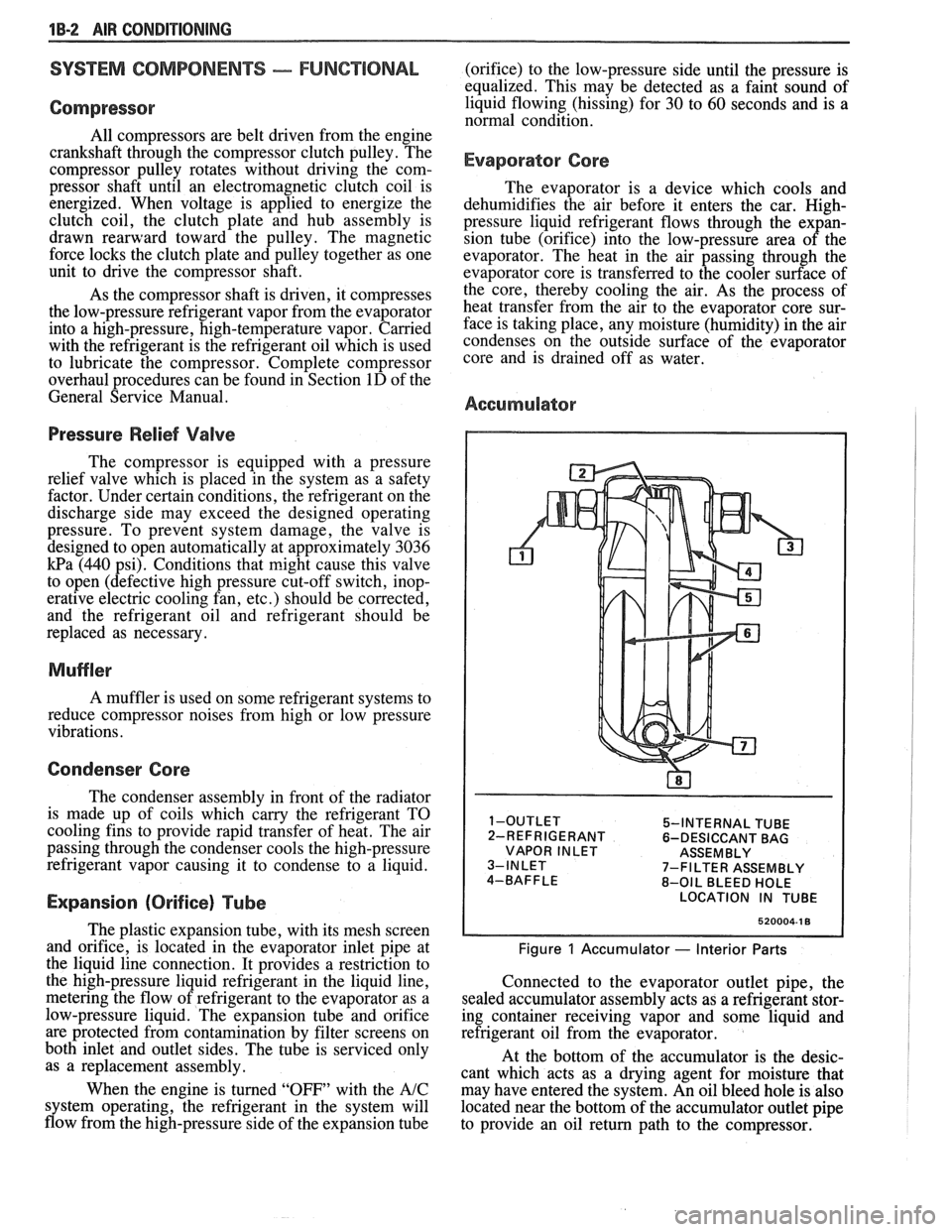
Accumulator
5-INTERNAL TUBE
2-REFRIGERANT 6-DESICCANT BAG
VAPOR INLET ASSEMBLY
7-FILTER ASSEMBLY
8-OIL BLEED HOLE
LOCATION IN TUBE
520004-1 8
Figure 1 Accumulator - Interior Parts
Connected to the evaporator outlet pipe, the
sealed accumulator assembly acts as a refrigerant stor-
ing container receiving vapor and some liquid and
refrigerant oil from the evaporator.
At the bottom of the accumulator is the desic-
cant which acts as a drying agent for moisture that
may have entered the system. An oil bleed hole is also
located near the bottom of the accumulator outlet pipe
to provide an oil return path to the compressor.
Page 294 of 1825
BRAKES
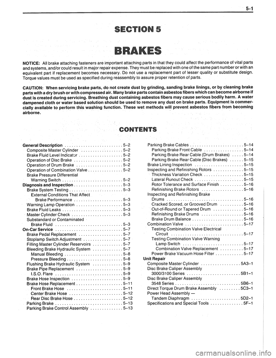
NOTICE: All brake attaching fasteners are important attaching parts in that they could affect the performance of vital parts
and systems.
andlor could result in major repair expense . They must be replaced with one of the same part number or with an
equivalent part if replacement becomes necessary
. Do not use a replacement part of lesser quality or substitute design .
Torque values must be used as specified during reassembly to assure proper retention of parts .
CAUTION: When servicing brake parts. do not create dust by grinding. sanding brake linings. or by cleaning brake
parts with a dry brush or with compressed air
. Many brake parts contain asbestos fibers which can become airborne if
dust is created during servicing
. Breathing dust containing asbestos fibers may cause serious bodily harm . A water
dampened cloth or water based solution should be used to remove any dust on brake parts
. Equipment is commer-
cially available to perform this washing function
. These wet methods will prevent asbestos fibers from becoming
airborne
.
CONTENTS
......................... General Description 5.2
Composite Master Cylinder
.................. 5.2
Brake Fluid Level
lndicatgr ................... 5.2
Operation of Disc Brake
..................... 5.2
Operation of Drum Brake
.................... 5.2
Operation of Combination Valve
............... 5.2
Brake Pressure Differential
.......................... Warning Switch 5.2
Diagnosis and Inspection ..................... 5.3
Brake System Testing
....................... 5.3
External Conditions That Affect Brake Performance
.................... -5-3
Warning Lamp Operation .................... 5.3
Brake Fluid Leaks
.......................... 5.3
Master Cylinder Check
...................... 5.3
Substandard or Contaminated
BrakeFluid ............................. 5-3
............................. On-Car Service 5.7
Brake Pedal Replacement
................... 5.7
Stoplamp Switch Adjustment ................. 5-7
Filling Master Cylinder Reservoirs
............. 5-7
Bleeding Brake Hydraulic System
............. 5.7
Manual Bleeding
......................... 5.8
Pressure Bleeding
........................ 5.8
Flushing Brake Hydraulic System
............. 5.9
Brake Pipe Replacement
.................... 5.9
............................. I.S.O. Flare 5.9
Brake Hose Inspection
...................... 5.9
Brake Hose Replacement
.................... 5.11
Front Brake Hose
........................ 5.11
....................... Center Brake Hose 5.12
..................... Rear Disc Brake Hose 5.12
ParkingBrake ............................. 5-13
Parking Brake Control Assembly
.............. 5.13 Parking Brake Cables
....................... 5.14
Parking Brake Front Cable
................. 5.14
Parking Brake Rear Cable (Drum Brakes)
..... 5.14
Parking Brake Rear Cable (Disc Brakes)
...... 5.15
Brake Lining Inspection
..................... 5.15
............. Inspecting and Refinishing Rotors 5-15
Thickness
Variat~on Check ................. 5.15
Lateral
Runout Check ..................... 5.15
Rotor Tolerance and Surface Finish
.......... 5.16
Refinishing Brake Rotors
.................. 5-16
lnspecting and Refinishing Brake
Drums
................................. 5-16
Cracked Scored, or Grooved Drum
.......... 5.16
Out-of-Round or Tapered Drum
............. 5.16
Refinishing Brake Drums
.................. 5.16
Brake Drum Balance
..................... -5-16
Combination Valve ......................... 5.17
Testing Combination Valve Electrical
............................... Circuit 5.17
Testing Combination Valve Warning
.......................... Lamp Switch 5.17
.......... Combination Valve Replacement 5.17
............ Power Brake Vacuum Hose Filter 5.17
Unit Repair
................ Composite Master Cylinder .5A 3.1
Disc Brake Caliper Assembly
....................... 300013100 Series 581 -1
Disc Brake Caliper Assembly
3548 Series
........................... .5B 6.1
........ Direct Torque Drum Brake Assembly .5C 3.1
Power Head Assembly
-
.................... Tandem Diaphragm .5D 2.1
.............. Specifications and Special Tools 5F-1
Page 299 of 1825
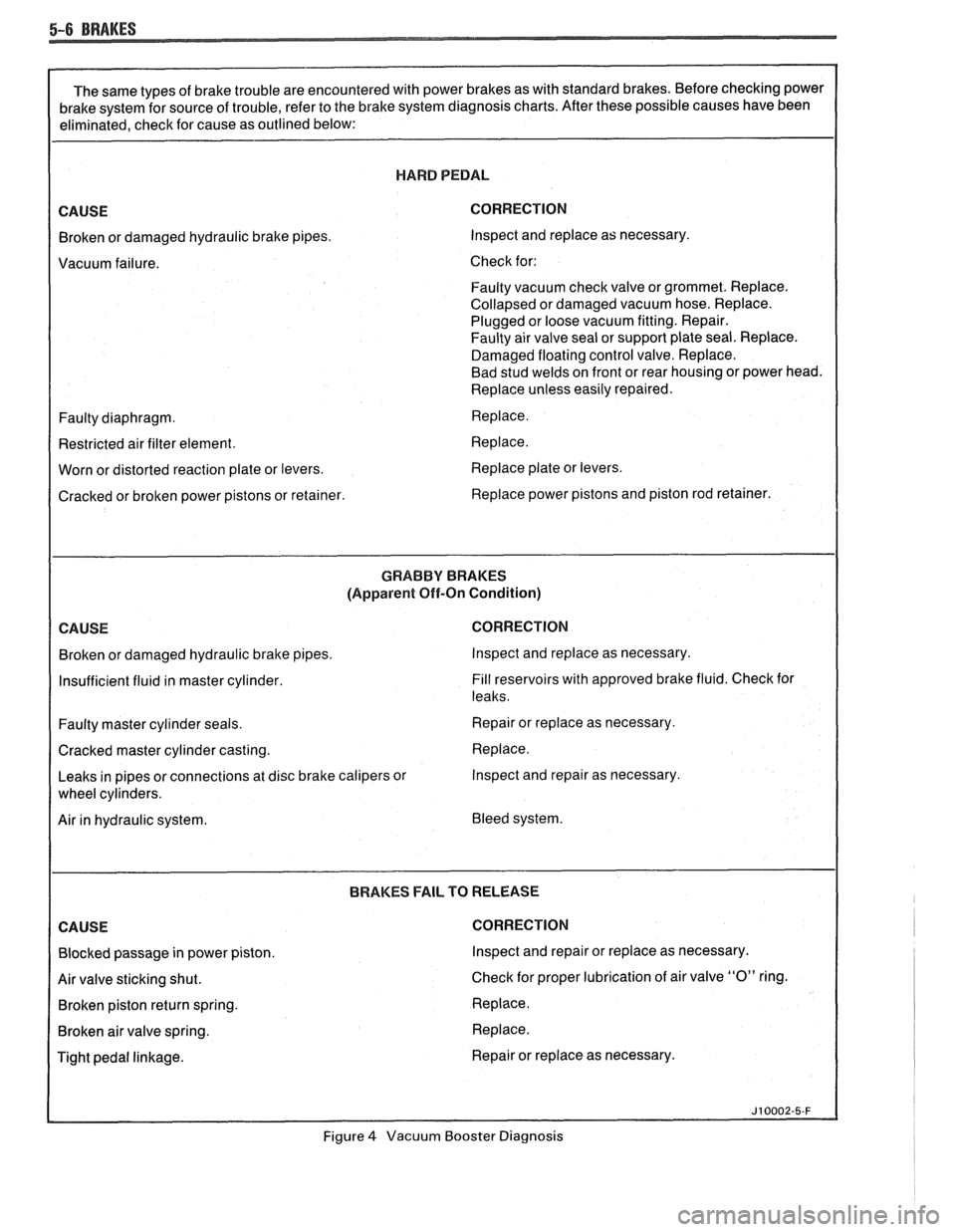
HARD PEDAL
CORRECTION
Broken or damaged hydraulic brake pipes. Inspect and replace
as necessary.
Vacuum failure. Check for:
Faulty vacuum check valve or grommet. Replace.
Collapsed or damaged vacuum hose. Replace.
Plugged or loose vacuum fitting. Repair.
Faulty air valve seal or support plate seal. Replace.
Damaged floating control valve. Replace.
Bad stud welds on front or rear housing or power head.
Replace unless easily repaired.
Faulty diaphragm. Replace.
Restricted air filter element. Replace.
Worn or distorted reaction plate or levers. Replace
plate or levers.
Cracked or broken power pistons or retainer. Replace power pistons and piston
rod retainer.
GRABBV BRAKES
(Apparent Off-On Condition)
CORRECTION
Broken or damaged hydraulic brake pipes. Inspect and replace
as necessary.
Insufficient fluid in master cylinder. Fill
reservoirs with approved brake fluid. Check for
leaks.
Faulty master cylinder seals. Repair or replace
as necessary.
Cracked master cylinder casting. Replace.
Leaks in pipes or connections at disc brake calipers or Inspect and repair
as necessary.
Air in hydraulic system. Bleed system.
BRAKES
FAIL TO RELEASE CORRECTION
Blocked passage in power piston. Inspect and repair or replace
as necessary.
Air valve sticking shut. Check
for proper lubrication of air valve
"0" ring.
Broken piston return spring. Replace.
Broken air valve spring. Replace.
Tight pedal linkage. Repair or replace
as necessary.
Figure
4 Vacuum Booster Diagnosis
Page 310 of 1825
BRAKES 5-17
maintaining proper wheel balance, brake drums should be
checked for balance. Brake drums may be checked for
balance on most off-the-car balancers.
COMBINATION VALVE
Testing Combination Valve Electrical Circuit
When removing the electrical wire connector from the
pressure differential switch, squeeze the
eliptical shaped
plastic locking ring and pull up. This will move the locking
tangs away from the switch. Pliers can be used to help
remove the connector.
1. Disconnect wire from switch terminal and use a
jumper to connect wire to a good ground.
2. Turn ignition key to "ON." The warning lamp should
light. If lamp does not light, bulb is burned out or
electrical circuit is faulty. Replace bulb or repair elec-
trical circuit as necessary.
3. When warning lamp lights, turn off ignition switch.
Disconnect jumper and connect wire to switch termi-
nal.
Testing Combination Valve Warning Lamp Switch
1. Attach a bleeder hose to a rear brake bleed screw and
immerse the other end of the hose in a container
partially filled with clean brake fluid. Be sure master
cylinder reservoirs are full.
2. Turn ignition switch to "ON." Open bleeder screw
while an assistant applies moderate pressure to the
brake pedal. Warning lamp should light. Close
bleeder screw before assistant releases brake pedal.
Apply brake pedal with moderate-to-heavy pressure.
Lamp should go out.
3. Attach the bleeder hose to a front brake bleeder
screw and repeat steps
1 and 2. Warning lamp action
should be the same as in step
2. Turn off ignition
switch.
4. If warning lamp does not light during steps 2 and 3,
but does light when a jumper is connected to ground,
the warning lamp switch portion of the combination
valve is faulty. Do not disassemble the combination
valve.
If any portion of the combination valve is faulty,
it must be replaced with a new combination valve.
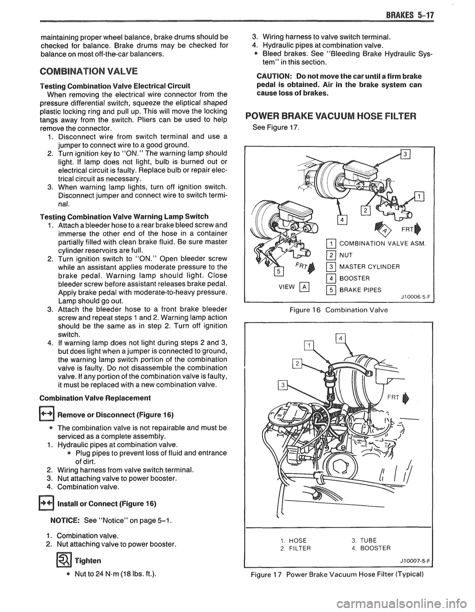
Combination Valve Replacement
Remove or Disconnect (Figure
16)
r The combination valve is not repairable and must be
serviced as a complete assembly.
1. Hydraulic pipes at combination valve.
Plug pipes to prevent loss of fluid and entrance
of dirt.
2. Wiring harness from valve switch terminal.
3. Nut attaching valve to power booster.
4. Combination valve.
@ Install or Connect (Figure 16)
NOTICE: See "Notice" on page 5-1.
1. Combination valve.
2. Nut attaching valve to power booster.
Tighten
* Nut to 24 N.m (18 Ibs. ft.).
3. Wiring harness to valve switch terminal.
4. Hydraulic pipes at combination valve. * Bleed brakes. See "Bleeding Brake Hydraulic Sys-
tem" in this section.
CAUTION: Do not move the car until a firm brake
pedal is obtained. Air in the brake system can
cause loss of brakes.
POWER BRAKE VACUUM HOSE FILTER
See Figure 17.
COMBINATION VALVE ASM.
MASTER CYLINDER BRAKE PIPES
Figure 16 Combination Valve
2 FILTER 4. BOOSTER
Figure 17 Power Brake Vacuum Hose Filter (Typical)
Page 336 of 1825
POWER HEAD ASSEMBLY 582-1
SECTION 582
POWER HEAD ASSEMBLY - TANDEM
APHRAGM
CONTENTS
...................... GENERAL DESCRIPTION 5D2-2 Unlocking and Locking Booster ................ 5D2-3
................................. ON-CAR SERVICE 5D2-2 Power Piston Group ................................. 5D2-3
..................................... Booster Assembly 5D2-2 Power Piston Disassembly ......................... 5D2-4
................................. Exterior Components 5D2-2 Gaging Procedure ...................................... 5D2-7
......................................... UNIT REPAIR 5D2-2
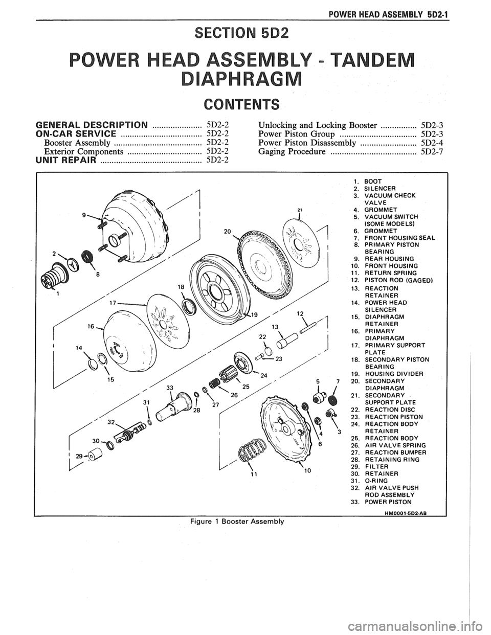
I 1. BOOT I 2. SILENCER 3. VACUUM CHECK
VALVE
4. GROMMET 5. VACUUM SWITCH
(SOME MODELS)
6. GROMMET 7. FRONT HOUSING SEAL 8. PRIMARY PISTON
BEARING
9. REAR HOUSING 10. FRONT HOUSING 11. RETURN SPRING 12. PISTON ROD (GAGED)
13. REACTION
RETAINER
14. POWER HEAD
SILENCER
15. DIAPHRAGM
RETAINER
16. PRIMARY
DIAPHRAGM
17. PRIMARY SUPPORT
PLATE
18. SECONDARY PISTON
BEARING
19. HOUSING DIVIDER 20. SECONDARY
DIAPHRAGM
21. SECONDARY
SUPPORT PLATE
22. REACTION DISC 23. REACTION PISTON 24. REACTION BODY
RETAINER
25. REACTION BODY 26. AIR VALVE SPRING 27. REACTION BUMPER 28. RETAINING RING 29. FILTER 30. RETAINER 31. O-RING 32. AIR VALVE PUSH
ROD ASSEMBLY
33. POWER PISTON
Figure 1 Booster Assembly