1988 PONTIAC FIERO remove seats
[x] Cancel search: remove seatsPage 22 of 1825
MAINTENANCE AND LUBRICATION OB-5
Throttle linkage inspection -- Inspect for inter-
ference, binding, damaged or missing parts.
Engine drive belts inspection - Inspect all
belts for cracks, fraying and wear. Adjust or replace as
needed.
Rear axle service (if equipped) - Check gear
lubricant level and add if needed. For cars equipped with a
limited slip rear axle, fluid does not require changing
(except Caprice and Corvette
- change fluid and required
additive at first
7,500 miles (12 500 km). See your
Owner's Manual or "Recommended Fluids
& Lubricants
Chart" in this section.
IF YOU USE YOUR GAR TO PULL A TRAILER,
CHANGE GEAR LUBRICANT EVERY 7,500 MILES
(12 500 KM).
NOTICE: A large loss in this system may indicate a
problem. Have it inspected and repaired at once.
Power antenna - Clean and then lubricate power
antenna mast. The proper lubricant as shown in Figure
OB-2 should be used.
AT LEAST ONCE A YEAR
Lap and shoulder belts condition and opera-
tion
- Inspect belt system, including webbing, buckles,
latch plates, retractors, guide loops and anchors.
Moveable head restraint operation - On cars
with moveable restraints, make sure restraints stay in the
desired position. (See adjustment instructions in your
Owner's Manual.)
Seatback latch and recliner operation on
cars equipped
with recliner seat --- Be sure seat-
backs latch on those cars with folding seats using mechan-
ical latches. Make sure the recliner is holding by pushing
and pulling on the top of the
seatback while it is reclined.
See your Owner's Manual for seat operating information.
Spare tire and jack storage- Be alert to rattles
in rear of car. Make sure the space tire, all jacking equip-
ment, any tire inflator and any covers or doors are securely
stowed at all times. Oil jack ratchet or screw mechanism
after each use.
Key lock service - Lubricate key lock cylinder at
least annually.
Body lubrication service - Lubricate all body
door hinges including the tailgate or hatchback lid (if
equipped). Also lubricate the body hood, fuel door and
rear compartment hinges and latches including interior
glove box and counsel doors, and any folding seat
hardware.
"Fansmissionltransaxle neutral or clutch
starl switch operation
CAUnON: Before pedorming the follow-
ing safety switch check, be sure to have
enough room around the car. Then, firmly
apply both the parking brake (see your
Owner's Manual for procedure) and the
regular brakes. Do not use the accelerator pedal.
If the engine
starls, be ready to turn
off the ignition promptly. Take these pre-
cautions because the car could move
without warning and possibly cause per-
sonal injury or properly damage. On auto-
matic transmissionltransaxle cars, try to
starl the engine in each gear. The starler
should crank only in "Park" or "Neutral."
On manual transmissionltransaxle cars,
place the
shiR lever in "Neutral," push the
clutch halfway and try to starl. The starler
should crank only when the clutch is fully
depressed.
Steering column lock operation
- While
parked, try to turn key to "Lock" in each gear range. The
key should turn to "Lock" only when gear is in "Park" on
automatic or "Reverse" on manual
transmissionltransax-
le. On cars with key release lever, try to turn key toULock"
without depressing the lever. The key should turn to
"Lock" only with the key lever depressed. On all vehicles,
the key should come out only in "Lock."
Parking brake and transmissionltransaxle
"Park" mechanism operation
CAUT1ON:Before checking the holding
ability of the parking brake and automatic
transmissionltransaxle "Park" mecha-
nism, park on a fairly steep hill with
enough room for movement in the down-
hill direction. To reduce the risk of person-
al injury or property damage, be prepared
to apply the regular brakes promptly if the
car begins to move.
To check the parking brake, with the engine running and
transmission/transaxle in "Neutral." slowly remove foot
pressure from the regular brake pedal (until the car is held
by only the parking brake).
To check the automatic transmissionltransaxle "Park"
mechanism holding ability, release all brakes after shift-
ing the transmissionltransaxle to "Park."
ljnderbody flushing - At least every spring,
tlush from the underbody with plain water any corrosive
materials used for ice and snow removal and dust control.
Take care to thoroughly clean any areas where mud and
other debris can collect.
Sediment packed in closed areas
of the vehicle should be loosened before being flushed.
Engine cooling system service - Inspect
coolant and freeze protection. If dirty or rusty, drain, flush
and refill with new coolant. Keep coolant
at the proper
mixture as specified in your Owner's Manual. This pro-
vides proper freeze protection. corrosion inhibitor level
and engine operating temperature. Inspect hoses and re-
place if cracked. swollen or deteriorated. Tighten hose
clamps. Clean outside of radiator and air conditioning
condensor. Wash radiator filler cap and neck.
To help
ensure proper operation. a pressure test of both the cooling
system and cap is also recommended. (See maintenance
schedule charts in Figure
OB-l for the recommended
coolant change interval.)
Page 57 of 1825
18-14 AIR CONDITIONING
HANDLING OF REFRIGERANT LINES AND
FI-INGS
Tighten all tubing connections as shown in
torque chart (Figure 13). INSUFFICIENT OR
EXCESSIVE TORQUE WHEN TIGHTENING CAN
RESULT IN LOOSE JOINTS OR DEFORMED
JOINT PARTS. Either condition can result in refrig-
erant leakage.
All metal tubing lines should be free of dents or
kinks to prevent loss of system capacity due to line
restriction.
@ The flexible hose lines should never be bent to a
radius of less than four (4) times the diameter of
the hose.
@ The flexible hose lines should never be allowed
to come within a distance of
63.5mm (2-112") of
the exhaust manifold.
@ Flexible hose lines should be inspected regularly
for leaks or brittleness and replaced with new
lines if deterioration or leaking is found.
@ When disconnecting any fitting in the refrigera-
tion system, the system must first be discharged
of all Refrigerant- 12. Proceed very cautiously
regardless of gauge readings. Open very slowly,
keeping face and hands away so that no injury
can occur if there happens to be liquid
Refriger-
ant-12 in the line. If pressure is noticed when
fitting is loosened, allow it to bleed off as
described under DISCHARGING, ADDING
OIL, EVACUATING AND CHARGING PRO-
CEDURES FOR
A/C SYSTEMS.
@ In the event any refrigerant line is opened to the
atmosphere, it should be immediately capped or
taped to prevent entrance of moisture and dirt,
which can cause internal compressor wear or
plugged lines, in the condenser and evaporator
core and expansion (orifice) tubes or compressor
inlet screens.
@ The use of the proper wrenches when making
connections on O-ring fittings is important. The
opposing fitting should always be backed up
with a wrench to prevent distortion of connecting
lines or components. When connecting the flexi-
ble hose connections, it is important that the
swaged fitting and the flare nut, as well as the
coupling to which it is attached, be held at the
same time using three
(3) different wrenches to
prevent turning the fitting and damaging the
ground seat.
@ O-rings and seats must be in perfect condition. A
burr or piece of dirt may cause a refrigerant leak.
When replacing the O-ring, first dip it in clean
525 viscosity refrigeration oil.
MAINTAINING CHEMICAL STABILITY IN
THE
REFRIGERATION SYSTEM
The efficient operation and life of the air condi-
tioning system is dependent upon the chemical stabil-
ity of the refrigeration system. When foreign materials, such as
dirt, air, or moisture, contaminate
the refrigeration system, they will change the stability
of the Refrigerant-12 and 525 viscosity compressor
oil. They will also affect pressure-temperature rela-
tionship, reduce efficient operation and possibly cause
interior corrosion and abnormal wear of moving parts.
The following general practices should be
observed to insure chemical stability in the system:
1. Before disconnecting a refrigerant connection,
wipe away any dirt or oil at and near the connec-
tion to reduce the possibility of dirt entering the
system. Both sides of the connection should be
capped, plugged or taped as soon as possible to
prevent the entry of dirt, foreign material and
moisture.
2. Keep tools clean and dry. This includes the
manifold gauge set and replacement parts.
3. When adding 525 viscosity refrigerant oil (see
ADDING OIL in the DISCHARGING,
ADDING OIL, EVACUATING AND
CHARGING PROCEDURES FOR
AIC SYS-
TEMS, the transfer device and container should
be clean and dry to assure that refrigeration oil
remains as moisture-free as possible.
4. When it is necessary to "open" an
AIC system,
have everything needed ready and handy so that
as little time as possible will be required to per-
form the operation. Do not leave the
AIC system
open any longer than is necessary.
5. Any time the
A/C system has been "opened," it
should be properly evacuated before recharging
with Refrigerant- 12 according to the DIS-
CHARGING, ADDING OIL, EVACUATING
& CHARGING PROCEDURES FOR AIC
SYSTEMS.
All service parts are dehydrated and sealed
prior to shipping. They should remain sealed until just
prior to making connections. All parts should be at
room temperature before uncapping. (This prevents
condensation of moisture from the air entering the
system.) If, for any reason, caps are removed but the
connections are not made, parts should be resealed as
soon as possible.
DISCHARGING, ADDING OIL,
EVACUATING AND CHARGING
PROCEDURES FOR NC SYSTEMS
The refrigerant system may be discharged,
evacuated and charged using air conditioning service
charging station J-23500-01 or equivalent, or the
manifold and gauge set
5-23575-01 and 420ml (14
oz.) disposable cans of Refrigerant-12 (Figure 16).
Charging lines from the charging station or
manifold and gauge set require the use of gauge
adapters to connect to the system service fitting.
A
straight gauge adapter 5-5420 and a 90" angle gauge
adapter
5-9459 are available (see A/C Special Tools).
Always wear goggles and wrap a clean cloth
around fittings and connections when doing work that
Page 145 of 1825
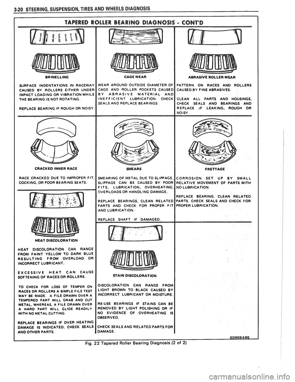
BRINELLING
SURFACE INDENTATIONS IN RACEWAY
CAUSED BY ROLLERS EITHER UNDER
IMPACT LOADING OR VIBRATION WHILE
THE BEARING IS NOT ROTATING.
REPLACE BEARING IF ROUGH OR NOISY. CAGE WEAR
WEAR AROUND OUTSIDE DIAMETER OF
CAGE AND ROLLER POCKETS CAUSED
BY ABRASIVE MATERIAL AND
INE FF IClENT LUBRICATION CHECK
SEALS AND REPLACE BEARINGS. ABRASIVE
ROLLER WEAR
PATTERN ON RACES AND ROLLERS
CAUSED BY
FINE ABRASIVES.
CLEAN ALL PARTS AND HOUSINGS,
CHECK SEALS AND BEARINGS AND
REPLACE IF LEAKING, ROUGH
OR NOISY
CRACKED INNER RACE
WEARS FRETfAGE
RACE CRACKED DUE TO IMPROPER FIT, SMEARING OF METAL DUE TO SLIPBAGE, CORROSION SET UP BY SMALL
COCKING. OR POOR BEARING SEATS. SLIPPAGE CAN BE CAUSED BY POOR RELATIVE MOVEMENT OF PARTS WITH I F ITS. LUBRICATION, OVERHEATING,
OVERLOADS OR HANDLING DAMAGE
REPLACE BEARING. CLEAN RELATED
REPLACE BEARINGS, CLEAN RELATED
PARTS AND CHECK FOR PROPER FIT
I AND LUBRICATION. I I
HEAT DISCOLORATION CAN RANGE
FROM FAINT YELLOW TO DARK BLUE
RESULTING FROM OVERLOAD OR
INCORRECT LUBRICANT.
EXCESSIVE HEAT CAN CAUSE
SOFTENING OF RACES
OR ROLLERS.
TO CHECK FOR LOSS OF TEMPER ON
RACES OR ROLLERS A SIMPLE
FlLE TEST MAY BE MADE. A FILE DRAWN OVER A
TEMPERED PART WlLL GRAB AND CUT
METAL. WHEREAS, A FlLE DRAWN OVER
A HARD PART WlLL GLIDE READILY WlTH NO METAL CUTTING
REPLACE BEARINGS IF OVER HEATING
DAMAGE IS INDICATED. CHECK SEALS
AND OTHER PARTS.
mAIN DISCOLORATION
I DISCOLORATION CAN RANGE FROM
LIGHT BROWN TO BLACK CAUSED BY
INCORRECT LUBRICANT OR MOISTURE.
RE-USE BEARINGS IF STAINS CAN BE
REMOVED BY LIGHT POLISHING OR IF
NO EVIDENCE OF OVERHEATING IS
OBSERVED.
CHECK SEALS AND RELATED PARTS FOR
DAMAGE.
Page 224 of 1825
REAR SUSPENSION 30-3
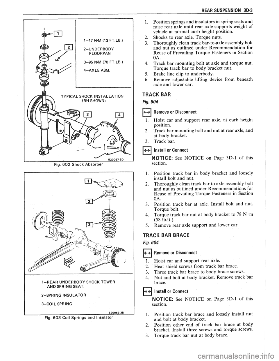
1. Position springs and insulators in spring seats and
raise rear axle until rear axle supports weight of
vehicle at normal curb height position.
2. Shocks to rear axle. Torque nuts. 1-17 N.M (13 FT.LB.1 3. Thoroughly clean track bar-to-axle assembly bolt
2-UNDERBODY and nut as outlined under Recommendation for
Reuse of Prevailing Torque Fasteners in Section
3-95 NeM (70 FT.LB.) 4. Track bar mounting bolt at axle and torque nut.
4-AXLE ASM. Torque track bar to body bracket nut.
5. Brake line clip to underbody.
6. Remove adjustable lifting device from beneath
axle and lower car.
TYPICAL SHOCK INSTALLATION TRACK BAR (RH SHOWN)
Remove or Disconnect
at body bracket.
3. Track bar.
Install or Connect
NOTICE: See NOTICE on Page 3D-1 of this
1. Position track bar in body bracket and loosely
install bolt and nut.
2. Thoroughly clean track bar to axle assembly bolt
and nut as outlined under Recommendations for
Reuse of Prevailing Torque Fasteners in Section
3. Position track bar at axle. Install bolt and nut.
4. Torque track bar nut at body bracket to 78 Nem
5. Remove rear axle support and lower car.
TRACK BAR BRACE
1. Hoist car and support rear axle.
2. Heat shield screws from track bar brace.
3. Three track bar brace to body brace screws.
4. Nut and bolt at body bracket. Remove track bar 1-REAR UNDERBODY SHOCK TOWER
AND SPRING SEAT.
2-SPRING INSULATOR
NOTICE: See NOTICE on Page 3D-1 of this 3-COIL SPRING
1. Position track bar brace and loosely install nut Fig. 603 Coil Springs and Insulator and bolt at body bracket.
2. Position other end of track bar brace at body
bracket. Install three screws and torque screws.
3. Torque track bar nut at body brace.
Page 227 of 1825
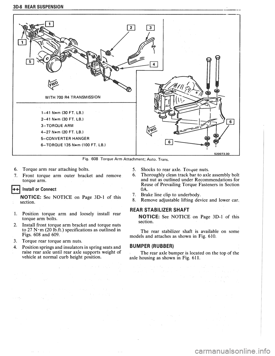
30-8 WEAR SUSPENSION
WITH 700 R4 TRANSMISSION
1-41 Nern (30 FT.
LB.)
2-41 Nern (30 FT. LB.)
3-TORQUE ARM
4-27 Nern
(20 FT. LB.)
5-CONVERTER HANGER
6-TORQUE 135
Nern (100 FT. LB.)
Fig. 608 Torque Arm Attachment; Auto. Trans.
6. Torque arm rear attaching bolts. 5. Shocks to rear axle. Toique nuts.
7. Front torque arm outer bracket and remove
6. Thoroughly clean track bar to axle assembly bolt
torque arm. and nut
as outlined under Recommendations for
Reuse of Prevailing Torque Fasteners in Section
Install or Connect OA.
7. Brake line clip to underbody. On Page 3D-1 of this 8. Remove adjustable lifting device and lower car.
section.
1. Position torque arm and loosely install rear
torque arm bolts.
2. Install front torque arm bracket and torque nuts
to 27
N.m (20 1b.ft.) specifications as outlined in
Figs.
608 and 609.
3.
Torque rear torque arm nuts.
4. Position springs and insulators in spring seats and
raise rear axle until rear axle supports weight of
vehicle at normal curb height position.
REAR STABILIZER SHAFT
NOTICE: See NOTICE on Page 3D-1 of this
section.
The rear stabilizer shaft is available on some
models and attaches as shown in Fig.
610.
BUMPER (RUBBER)
The rear axle bumper is located on the top of the
axle housing as shown in Fig.
61 1.
Page 236 of 1825
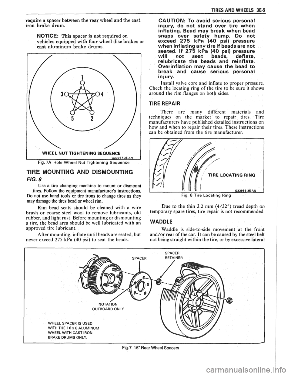
TIRES AND WI4EELS 3E-5
require a spacer between the rear wheel and the cast
iron brake drum.
NOTICE: This spacer is not required on
vehicles equipped with four wheel disc brakes or
cast aluminum brake drums.
Fig. 7A Hole Wheel Nut Tightening Sequence
TlRE MOUNTING AND DISMOUNTING
FIG. 8
Use a tire changing machine to mount or dismount
tires. Follow the equipment manufacturer's instructions.
Do not use hand tools or tire irons to change tires as they
may damage the tires bead or wheel rim.
Rim bead seats should be cleaned with a wire
brush or coarse steel wool to remove lubricants, old
rubber, and light rust. Before mounting or dismounting
a tire, the bead area should be well lubricated with an
approved tire lubricant.
After mounting, inflate until beads are seated, but
never exceed 275
kPa (40 psi) to seat the beads.
CAUTION: To avoid serious personal
injury, do not stand over tire when
inflating. Bead may break when bead
snaps over safety hump. Do not
exceed
275 kPa (40 psi) pressure
when inflating
any tire if beads are not
seated. If
275 kPa (40 psi) pressure
will not seat beads, deflate,
relubricate the beads and reinflate.
Overinflation may cause the bead to
break and cause serious personal
injury.
Install valve core and inflate to proper pressure.
Check the locating ring of the tire to be sure it shows
around the rim flanges on both sides.
TIRE REPAIR
There are many different materials and
techniques on the market to repair tires. Tire
manufacturers have published detailed instructions on
how and when to repair their tires. These instructions
can be obtained from the tire manufacturer.
TlRE LOCATING RING
naaaca a= AM
Fig. 8 Tire Locating Ring
Due to the thin 3.2 mm (4/32") tread depth on
temporary spare tires, tire repair is not recommended.
WADDLE
Waddle is side-to-side movement at the front
and/or rear of the car. It can be caused by the steel belt
not being straight within the tire, or by excessive lateral
WHEEL SPACER IS USED
WITH THE
16 x 8 ALUMINUM
WHEEL WITH CAST IRON
BRAKE DRUMS ONLY.
Fig, 7 16 Rear Wheel Spacers
Page 250 of 1825
PROPELLER SHAFT 4A-9
damage, do not place any tool betvveen pro-
peller shaft yoke and the universal joint
spider.
When making the rear propeller shaft connection,
be sure to align marks made on the pinion flange and
propeller shaft prior to removal.
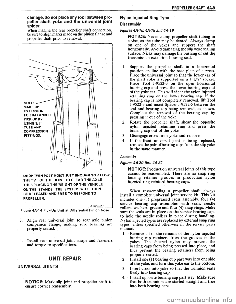
DROP TWIN POST HOIST JUST ENOUGH TO ALLOW
THE
"V" OF THE HOIST TO CLEAR THE AXLE
THUS PLACING THE WEIGHT OF THE VEHICLE
ON THE STANDS. THE SYSTEM
WILL THEN
BE RELEASED AND FREE TO RESPOND TO
PROPELLER.
Figure 4A-14 Pick-Up Unit at Differential Pinion Nose
3. Align rear universal joint to rear axle pinion
companion flange, making sure bearings are
properly seated.
4. Install rear universal joint straps and fasteners
and torque to specifications.
UNIT REPAIR
UNIVERSAL JOINTS
NOTICE: Mark slip joint and propeller shaft to
ensure correct reassembly.
Nylon Injected Ring Type
Disassembly
Figures 4A-16,4A-18 and 4A-19
NOTICE: Never clamp propeller shaft tubing in
a vise, as the tube may be dented. Always clamp
on one of the yokes and support the shaft
horizontally. Avoid damaging the slip yoke sealing
surface. Nicks may damage the bushing or cut the
transmission extension housing seal.
1. Support the propeller shaft in a horizontal
position on line with the base plate of a press.
Place the universal joint so that the lower ear of
the shaft yoke is supported on a
1 1/8" socket.
Place Tool
J-9522-3 on the open horizontal
bearing cap and press the lower bearing cap out
of the yoke ear. This will shear the nylon injected
retaining ring on the lower bearing cap. If the
bearing cap is not completely removed, lift Tool
5-9522-3 and insert Spacer J-9522-5 between the
seal and bearing cap being removed, as shown.
Complete the removal of the bearing cup by
pressing it out of the yoke.
2. Rotate
the propeller shaft, shear the opposite
nylon injected retaining ring and press the
bearing cap out of the yoke.
3. Disengage cross from yoke and remove.
4. If the front universal joint is being replaced,
remove the pair of bearing caps from the slip yoke
in the same manner.
Assembly
Figures 4A-20 thru 4A-22
NOTICE: Production universal joints of this type
cannot be reassembled. There are no snap ring
bearing retainer grooves in production nylon
injected ring retained bearing caps.
When reassembling a propeller shaft, always
install a complete universal joint service kit. This kit
includes one
(1) pregreased cross assembly, four (4)
service bearing cap assemblies with seals, needle
rollers, washers, grease and four
(4) snap rings. Make
sure the seals are in place on the service bearing caps
to hold the needle rollers in place during handling.
Nylon injected types are replaced by external snap ring
types, unless specified otherwise in the service parts
manual.
1. Remove all of the remains of the nylon injected
bearing cap retainers from the grooves in the
yokes. The sheared nylon may prevent the
bearing caps from being pressed into place, and
thus prevent the bearing retainers from being
properly seated.
2. Install one (1) bearing cup part way into one side
of the yoke, and turn this yoke ear to the bottom.
3. Insert cross into yoke so that the trunnion seats
freely into bearing cap.
4. Install opposite bearing cap part way. Make sure
that both trunnions are started straight and true
into both bearing caps.
Page 252 of 1825
I
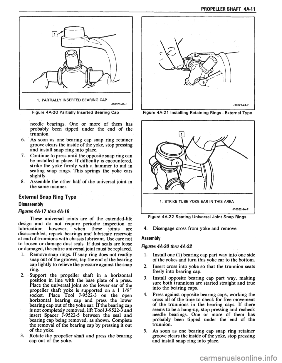
1. PARTIALLY INSERTED BEARING CAP J10020-4A-F I
Figure 4A-20 Partially Inserted eari in^ Cap
needle bearings. One or more of them has
probably been tipped under the end of the
trunnion.
6. As soon as one bearing cap snap ring retainer
groove clears the inside of the yoke, stop pressing
and install snap ring into place.
7. Continue to press until the opposite snap ring can
be installed in place. If difficulty is encountered,
strike the yoke firmly with a hammer to aid in
seating snap rings. This springs the yoke ears
slightly.
8. Assemble the other half of the universal joint in
the same manner.
External Snap Ring Type
Disassembly
Figures 4A- 17 thru 4A- 19
These universal joints are of the extended-life
design and do not require periodic inspection or
lubrication; however, when these joints are
disassembled, repack bearings and lubricate reservoir
at end of trunnions with chassis lubricant. Use care not
to loosen or damage dust seals. If dust seals are loose
or damaged, the entire universal joint must be replaced.
1. Remove snap rings. If snap ring does not readily
snap out of the grooves, tap the end of the bearing
cap lightly to relieve the pressure against the snap
ring.
2. Support the propeller shaft in a horizontal
position in line with the base plate of a press.
Place the universal joint so the lower ear of the
propeller shaft yoke is supported on a
1 1/8"
socket. Place Tool J-9522-3 on the open
horizontal bearing cap and press the lower
bearing cap out of the yoke ear. If the bearing cap
is not completely removed, lift Tool
9-9522-3 and
insert Spacer
J-9522-5 between the seal and
bearing cap being removed, as shown. Complete
the removal of the bearing cap by pressing it out
of the yoke.
3. Rotate the propeller shaft and press the bearing
cap out of the yoke.
PROPELLER SHAFT 4A-11
I I Figure 4A-2 1 Installing Retaining Rings - External Type
I 1. STRIKE TUBE YOKE EAR IN THIS AREA I
Figure 4A-22 Seating Universal Joint Snap Rings
4. Disengage cross from yoke and remove.
Assembly
Figures 4A-20 thru 4A.22
1. Install one (1) bearing cap part way into one side
of the yokes and turn this yoke ear to the bottom.
2. Insert cross into yoke so that the trunnion seats
freely into bearing cap.
3. Install opposite bearing cap part way, making
sure both trunnions are started straight and true
into the bearing caps.
4. Press against opposite bearing caps, working the
cross all of the time to check for free movement
of the trunnions in the bearing caps. If there
seems to be a hang-up, stop pressing and recheck
needle bearings. One or more of them has
probably been tipped under the end of the
trunnion.
5. As soon as one bearing cap snap ring retainer
groove clears the inside of the yoke, stop pressing
and install snap ring into place.