1988 PONTIAC FIERO service interval
[x] Cancel search: service intervalPage 19 of 1825
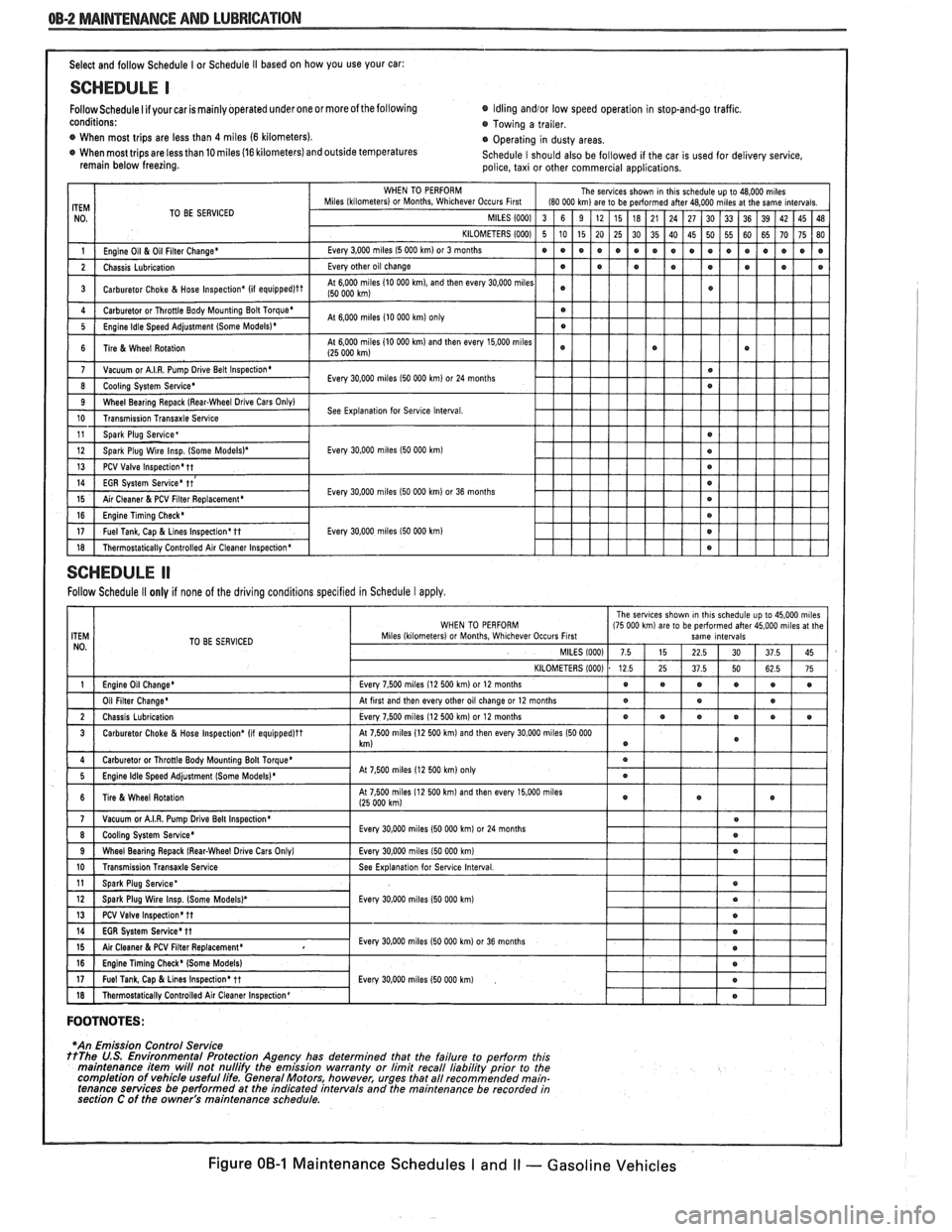
OB-2 MAINTENANCE AND LUBRICATION
Select and follow Schedule I or Schedule I1 based on how you use your car:
SCHEDULE I
Follow Schedule I if your car is mainly operated under one or moreof the following Idling andlor low
speed operation in stop-and-go traffic.
conditions: Towing a trailer.
@ When most trips are less than 4 miles (6 kilometers).
Operating in dusty areas.
When most trips are less than 10 miles (16 kilometers) and outside temperatures
Schedule I should also be followed if the car is used for delivery service,
remain below freezing.
police, taxi or other commercial applications.
TO BE SERVICED
Every
30.000 miles I50 000 km)
Every 30,000 miles I50 000 km) or 36 months
Every
30,000 miles 150 000 km)
SCHEDULE ll
Follow Schedule II only if none of the driving conditions specified in Schedule I apply.
TO BE SERVICED
At
7 500 miles 12 500 km on1
FOOTNOTES:
I
*An Emission Control Service ttThe U.S. Environmental Protection Agency has determined that the failure to perform this
maintenance item will not nullifv the emission warrantv or limit recall liabilitv orior to the
completion of vehicle useful life. General Motors, however, urges that all recommended main-
tenance services be performed at the indicated intervals and the maintenance be recorded in
section C of the owner's
ma~ntenance schedule.
Figure OB-1 Maintenance Schedules I and I1 - Gasoline Vehicles
Page 20 of 1825
F CARLINE
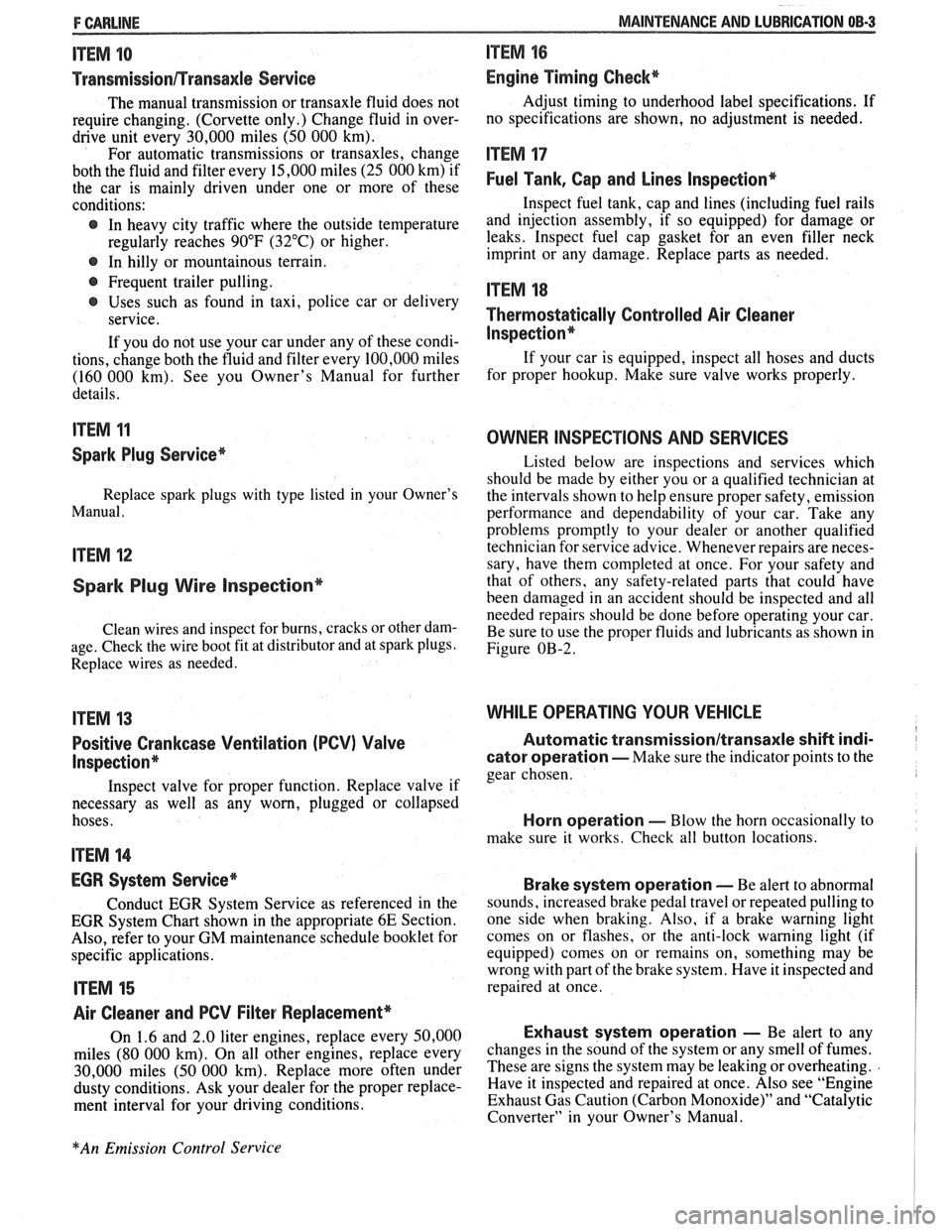
ITEM 10
TransmissionRransaxle Service
The manual transmission or transaxle fluid does not
require changing. (Corvette only.) Change fluid in over-
drive unit every 30,000 miles (50 000 km).
For automatic transmissions or transaxles, change
both the fluid and filter every 15,000 miles (25 000 km) if
the car is mainly driven under one or more of these
conditions:
@ In heavy city traffic where the outside temperature
regularly reaches 90°F (32°C) or higher.
@ In hilly or mountainous terrain.
@ Frequent trailer pulling.
@ Uses such as found in taxi, police car or delivery
service.
If you do not use your car under any of these condi-
tions, change both the fluid and filter every 100,000 miles
(160 000 km). See you Owner's Manual for further
details.
ITEM 11
Spark Plug Service*
Replace spark plugs with type listed in your Owner's
Manual.
ITEM 12
Spark Plug Wire Inspection*
Clean wires and inspect for burns, cracks or other dam-
age. Check the wire boot fit at distributor and at spark plugs.
Replace wires as needed.
ITEM 13
Positive Crankcase Ventilation (PCV) Valve
Inspection*
Inspect valve for proper function. Replace valve if
necessary as well as any worn, plugged or collapsed
hoses.
ITEM 14
EGR System Service*
Conduct EGR System Service as referenced in the
EGR System Chart shown in the appropriate 6E Section.
Also, refer to your GM maintenance schedule booklet for
specific applications.
ITEM 15
Air Cleaner and PCV Filter Replacement*
On 1.6 and 2.0 liter engines, replace every 50,000
miles (80 000 km). On all other engines, replace every
30,000 miles (50 000 km). Replace more often under
dusty conditions. Ask your dealer for the proper replace-
ment interval for your driving conditions.
MAINTENANCE AND LUBRICATION 08-3
ITEM 16
Engine Timing Check*
Adjust timing to underhood label specifications. If
no specifications are shown, no adjustment is needed.
ITEM 17
Fuel Tank, Cap and Lines Inspection*
Inspect fuel tank, cap and lines (including fuel rails
and injection assembly, if so equipped) for damage or
leaks. Inspect fuel cap gasket for an even filler neck
imprint or any damage. Replace parts as needed.
ITEM 18
Thermostatically Controlled Air Cleaner
Inspection*
If your car is equipped, inspect all hoses and ducts
for proper hookup. Make sure valve works properly.
OWNER INSPECTIONS AND SERVICES
Listed below are inspections and services which
should be made by either you or a qualified technician at
the intervals shown to help ensure proper safety, emission
performance and dependability of your car. Take any
problems promptly to your dealer or another qualified
technician for service advice. Whenever repairs are neces-
sary, have them completed at once. For your safety and
that of others, any safety-related parts that could have
been damaged in an accident should be inspected and all
needed repairs should be done before operating your car.
Be sure to use the proper fluids and lubricants as shown in
Figure OB-2.
WHILE OPERATING YOUR VEHICLE
Automatic transmissionltransaxle shift indi-
cator operation - Make sure the indicator points to the
gear chosen.
Horn operation - Blow the horn occasionally to
make sure it works. Check all button locations.
I
Brake system operation -- Be alert to abnormal
sounds, increased brake pedal travel or repeated pulling to
one side when braking. Also, if a brake warning light
comes on or flashes, or the anti-lock warning light (if
equipped) comes on or remains on, something may be
wrong with part of the brake system. Have it inspected and
repaired at once.
Exhaust system operation - Be alert to any
changes in the sound of the system or any smell of fumes.
These are signs the system may be leaking or overheating.
.
Have it inspected and repaired at once. Also see "Engine
Exhaust Gas Caution (Carbon Monoxide)" and "Catalytic
Converter" in your Owner's Manual.
*An Emission Control Service
Page 22 of 1825
MAINTENANCE AND LUBRICATION OB-5
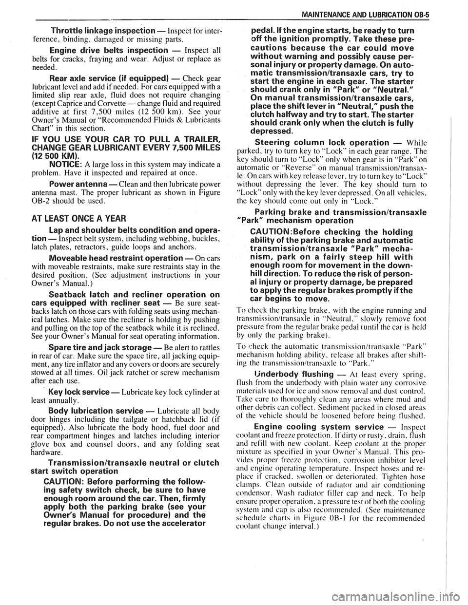
Throttle linkage inspection -- Inspect for inter-
ference, binding, damaged or missing parts.
Engine drive belts inspection - Inspect all
belts for cracks, fraying and wear. Adjust or replace as
needed.
Rear axle service (if equipped) - Check gear
lubricant level and add if needed. For cars equipped with a
limited slip rear axle, fluid does not require changing
(except Caprice and Corvette
- change fluid and required
additive at first
7,500 miles (12 500 km). See your
Owner's Manual or "Recommended Fluids
& Lubricants
Chart" in this section.
IF YOU USE YOUR GAR TO PULL A TRAILER,
CHANGE GEAR LUBRICANT EVERY 7,500 MILES
(12 500 KM).
NOTICE: A large loss in this system may indicate a
problem. Have it inspected and repaired at once.
Power antenna - Clean and then lubricate power
antenna mast. The proper lubricant as shown in Figure
OB-2 should be used.
AT LEAST ONCE A YEAR
Lap and shoulder belts condition and opera-
tion
- Inspect belt system, including webbing, buckles,
latch plates, retractors, guide loops and anchors.
Moveable head restraint operation - On cars
with moveable restraints, make sure restraints stay in the
desired position. (See adjustment instructions in your
Owner's Manual.)
Seatback latch and recliner operation on
cars equipped
with recliner seat --- Be sure seat-
backs latch on those cars with folding seats using mechan-
ical latches. Make sure the recliner is holding by pushing
and pulling on the top of the
seatback while it is reclined.
See your Owner's Manual for seat operating information.
Spare tire and jack storage- Be alert to rattles
in rear of car. Make sure the space tire, all jacking equip-
ment, any tire inflator and any covers or doors are securely
stowed at all times. Oil jack ratchet or screw mechanism
after each use.
Key lock service - Lubricate key lock cylinder at
least annually.
Body lubrication service - Lubricate all body
door hinges including the tailgate or hatchback lid (if
equipped). Also lubricate the body hood, fuel door and
rear compartment hinges and latches including interior
glove box and counsel doors, and any folding seat
hardware.
"Fansmissionltransaxle neutral or clutch
starl switch operation
CAUnON: Before pedorming the follow-
ing safety switch check, be sure to have
enough room around the car. Then, firmly
apply both the parking brake (see your
Owner's Manual for procedure) and the
regular brakes. Do not use the accelerator pedal.
If the engine
starls, be ready to turn
off the ignition promptly. Take these pre-
cautions because the car could move
without warning and possibly cause per-
sonal injury or properly damage. On auto-
matic transmissionltransaxle cars, try to
starl the engine in each gear. The starler
should crank only in "Park" or "Neutral."
On manual transmissionltransaxle cars,
place the
shiR lever in "Neutral," push the
clutch halfway and try to starl. The starler
should crank only when the clutch is fully
depressed.
Steering column lock operation
- While
parked, try to turn key to "Lock" in each gear range. The
key should turn to "Lock" only when gear is in "Park" on
automatic or "Reverse" on manual
transmissionltransax-
le. On cars with key release lever, try to turn key toULock"
without depressing the lever. The key should turn to
"Lock" only with the key lever depressed. On all vehicles,
the key should come out only in "Lock."
Parking brake and transmissionltransaxle
"Park" mechanism operation
CAUT1ON:Before checking the holding
ability of the parking brake and automatic
transmissionltransaxle "Park" mecha-
nism, park on a fairly steep hill with
enough room for movement in the down-
hill direction. To reduce the risk of person-
al injury or property damage, be prepared
to apply the regular brakes promptly if the
car begins to move.
To check the parking brake, with the engine running and
transmission/transaxle in "Neutral." slowly remove foot
pressure from the regular brake pedal (until the car is held
by only the parking brake).
To check the automatic transmissionltransaxle "Park"
mechanism holding ability, release all brakes after shift-
ing the transmissionltransaxle to "Park."
ljnderbody flushing - At least every spring,
tlush from the underbody with plain water any corrosive
materials used for ice and snow removal and dust control.
Take care to thoroughly clean any areas where mud and
other debris can collect.
Sediment packed in closed areas
of the vehicle should be loosened before being flushed.
Engine cooling system service - Inspect
coolant and freeze protection. If dirty or rusty, drain, flush
and refill with new coolant. Keep coolant
at the proper
mixture as specified in your Owner's Manual. This pro-
vides proper freeze protection. corrosion inhibitor level
and engine operating temperature. Inspect hoses and re-
place if cracked. swollen or deteriorated. Tighten hose
clamps. Clean outside of radiator and air conditioning
condensor. Wash radiator filler cap and neck.
To help
ensure proper operation. a pressure test of both the cooling
system and cap is also recommended. (See maintenance
schedule charts in Figure
OB-l for the recommended
coolant change interval.)
Page 189 of 1825
386-2 STEERING LINKAGE
LUBRICATION ADJUSTMENTS
The steering linkage should be lubricated with any
water resistant
EP type chassis lubricant at specified Toeein
intervals. Lubrication points and additional information on Adjust
the steering linkage for proper toe-in setting as
chassis lubrication can be found in Section
OB. outlined in Section 3A.
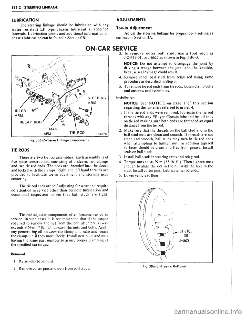
ON-CAR SERVICE 3. To remove outer ball stud, use a tool such as
RELAY ROD
Fig. 3B6-2--Series Linkage Components
TIE RODS
There are two tie rod assemblies. Each assembly is of
five piece construction, consisting of a sleeve, two clamps
and two tie rod ends. The ends are threaded into the sleeve
and locked with the clamps.
Right and left hand threads are
provided to facilitate toe-in adustment and steering gear
centering.
The tie rod ends are self-adjusting for wear and require
no attention in service other than periodic lubrication and
occasional inspection to see that ball studs are tight.
Tie rod adjuster components often become rusted
in
service. In such cases, it is recommended that if the torquc
required to remove the nut from thc bolt after break:iw:~>
exceeds 9 N.m (7 Ib, ft.), discard the nuts and bolth. Appl!
any penetrating oil betwoon thc clamp and tube ;~nd roliitc
the clamps until they movt. frcely. Install nc\4 bolts and nuts
having the same part number to assure proper clamping at
the specified nut torque.
Removal
I. qaise vehicle on hoiht.
2. Remove cotter pins and nuts from ball studs.
5-243 19-01, or 5-6627 as shown in Fig. 3B6-3
NOTICE: Do not attempt to disengage the joint by
driving a wedge between the joint and the knuckle,
because seal damage could result.
4. Remove inner ball stud from relay rod using same
procedure as described in Step 3.
5. To remove tie rod ends from tie rods, loosen clamp bolts
and unscrew end assemblies.
Installation
NOTICE: See NOTICE on page I of this section
regarding the fasteners referred to in step
4.
1. If the tie rod ends were removed, lubricate the tie rod
threads with any
EP type Chassis lube and install ends
on tie rod making sure both ends are threaded an equal
distance from the tie rod.
2. Make sure that the threads on the ball stud and in the
ball stud nuts are clean and smooth. If threads are not
clean and smooth, ball studs may turn in tie rod ends
when attempting to tighten nut. In addition tapered
surfaces should be clean and free from grease. Install
seals on ball studs.
3. Install ball studs in steering arms and relay rod.
4. Torque nuts to 48N.m (35 Ib. ft.). Then tighten nuts
enough to align the slot in the nut with the hole in the
stud. Install cotter pins. Lubricate tie rod
end\.
5. Lower vehicle to floor.
Fig. 3B6-3--Freeing Ball Stud
Page 347 of 1825
6-2 ENGINE GENERAL INFORMATION
6E3 - Fuel Injection (Ported) This section has information
on all exhaust
system parts, such as tailpipes, mufflers, and the
SECTION 6F - EXHAUST SYSTEM catalytic converter.
GENERAL INFORMAflION
CLEANLINESS AND CARE
An automobile engine is a combination of many
machined, honed, polished and lapped surfaces with
tolerances that are measured in the ten-thousandths of
an inch. When any internal engine parts are serviced,
care and cleanliness are important. A liberal coating of
engine oil should be applied to friction areas during
assembly, to protect and lubricate the surfaces on
initial operation. Throughout this section, it should be
understood that proper cleaning and protection of
machined surfaces and friction areas is part of the
repair procedure. This is considered standard shop
practice, even if not specifically stated. PREVENTING
DAMAGE AND IN
CONTRIBUTING TO RELIABLE ENGINE
PERFORMANCE.
When raising or supporting the engine for any
reason, do not use a jack under the oil pan. Due to the
small clearance between the oil pan and the oil pump
screen, jacking against the oil pan may cause it to be
bent against the pump screen resulting in a damaged
oil pick-up unit.
When working on the engine, remember that the
12-volt electrical system is capable of causing short
circuits. When performing any work where electrical terminals could possibly be grounded, the ground cable
of the battery should be disconnected at the battery.
Any time the carburetor or air cleaner is
train components are removed removed, the intake opening should be covered. This for service, they should be in order' will protect against entrance of foreign be installed in the same locations, and with the same material, which could follow the intake passage into mating surfaces, as when removed
the cylinder and cause extensive damage when the -
Battery cables should be disconnected before any engin; is started.
major work is performed on the engine. Failure to IN THE MECHANICAL PROCEDURES
disconnect cables may result in damage to wire harness DESCRIBED IN THIS SECTION, GENERALLY
or other electrical parts. NO
REFERENCES WILL BE MADE TO THE
REMOVAL OF OPTIONAL EQUIPMENT SUCH
ENGINE SERVICE AS POWER STEERING PUMP, AIR
CONDITIONING COMPRESSOR, ETC.
THE FOLLOWING INFORMATION ON SHOULD IT BECOME NECESSARY TO
ENGINE SERVICE SHOULD BE NOTED REMOVE ANY SUCH ITEM TO
PERFORM
CAREFULLY, AS IT IS IMPORTANT IN OTHER SERVICE, REFER TO THE
APPROPRIATE SECTION OF THIS SERVICE
MANUAL FOR SPECIFIC INFORMATION.
ENGINE PERFORMANCE DIAGNOSIS
INTRODUCTION interchangeably for so long, it was necessary to decide
on the most common usage and then define them. If the
Engine Performance procedures are definition is not understood, and the exact Symptom is
guides that will lead to the most probable causes of not used, the Diagnostic procedure will not work. engine performance complaints. They cover the
components of the fuel, ignition, and mechanical It
is important to keep two facts in mind:
systems that could cause a particular
complaint, and 1. The procedures are written to diagnose problems
then outline repairs in a logical sequence. on cars
that have
"run well at one time" and
that time and wear have created the condition.
It is important to determine if the
"Service ~~~i~~ soon- light is "ON,~' or has come for 2. All possible causes cannot be covered,
a short interval while driving. If the
"Service Engine particularly with regard to emission controls. If
Soon" light has come "ON," the Computer doing the work prescribed does not correct the
Command Control System or DECS should be complaint, then either the wrong Symptom was
checked for stored
"Trouble Codes" (See Diagnostic used, or a more detailed analysis will have to be
Circuit Check, Section 6E, for the engine you are made.
working on) which may indicate the cause for the All of the Symptoms can be caused by worn out
performance
complaint.Each Symptom is defined, and or defective parts such as Spark Plugs, Ignition
it is important that the correct one be selected, based Wiring, etc. If time and/or mileage indicate that
on the complaints reported or found. The definition of parts should be replaced, it is recommended that
each symptom is included with the symptom. it
be done.
The words used may not be what you are used to Refer to:
in all cases, but because these terms have been used
@ Section 6E - Driveability and Emissions
Page 464 of 1825
CHARGING SYSTEM 6D3-1
SECTION 6D3
CHARG NG SYSTEM
CONTENTS
General Description ................................. 6D3- 1 Charging System ........................................ 6D3- 1
.......................................... Charging System - CS ............................... 6D3- 1 On-Car Service 6D3-2
................................................... Diagnosis .. 6D3- 1 Generator 6D3-3 ...................... ......................... ............................................. 6D3- 1 Specifications 6D3-3 Service Procedures .................................. Unit Repair .. 6D3-4-6 ............................... ............
GENERAL DESCRIPTION
The engine electrical system includes the battery,
ignition (primary and secondary), starter (and related
wiring) and the generator (and related wiring).
Diagnostic charts (see Section 6D) will aid in
trouble-shooting system faults. When a fault is traced
to a particular component, refer to that components'
section of the service manual.
CHARGING SYSTEM-CS
The CS Charging System has several sizes
available, including the CS-130 and CS-144. The
number (130 or 144) denotes the
OD in mm of the
stator laminations.
CS generators use a new type regulator and a
diode trio is not used. A delta stator, rectifier bridge,
and rotor with slip rings and brushes are electrically
similar to earlier generators. A conventional pulley and
fan is used and, on the CS-130, an internal fan cools the
slip ring end frame, rectifier bridge and regulator.
Unlike three-wire generators, the CS-130 and
CS-144 may be used with only two connections
-
battery positive and an "L" terminal to the charge
indicator bulb. Use of "P",
"F", and "S" terminals is
optional. The "P" terminal is connected to the stator,
and may be connected externally to
a tachometer or other
device. The
"F" terminal is connected internally
to field positive, and may be used as a fault indicator.
The "S" terminal may be connected externally to a
voltage, such as battery voltage, to sense voltage to be
controlled.
As on other charging systems, the charge
indicator lights when the switch is closed, and goes out
when the engine is running. If the charge indicator is
on with the engine running, a charging system defect
is indicated. For all kinds of defects, the indicator will
glow at full brilliance, not "half lit". Also, the charge
indicator will be on with the engine running if system
voltage is too high or too low. The regulator voltage
setting varies with temperature, and limits system
voltage by controlling rotor field current.
This regulator switches rotor field current on and
off at a fixed frequency of about 400 cycles per second.
By varying the on-off time, correct average field
current for proper system voltage control is obtained.
At high speeds, the on-time may be 10% and the
off-time 90%. At low speeds, with high electrical loads,
on-off time may be 90% and
lo%, respectively.
No periodic maintenance on the generator is
required.
DIAGNOSIS
SERVICE PROCEDURES
CHARGING SYSTEM
The generator does not require periodic
lubrication. The rotor shaft is mounted on ball bearings
at the drive end and roller bearings at the slip ring end.
Each contains a permanent grease supply. At periodic
intervals, check mounting bolts for tightness and adjust
belt tension (see Section
6B), if applicable.
e When adjusting belt tension, apply pressure at
center of generator, never against either end
frame.
GENERATOR BENCH CHECK-CS
To check generator in a test stand, remove as
specified in On-Car Service and proceed as follows: 1.
Make connections as shown in Figure
lH, except
leave the carbon pile disconnected. The ground
polarity of generator and battery must be the
same. The battery must be fully charged. Use a
30-500
OHM resistor between battery and "L"
terminal.
2. Slowly increase generator speed and observe
voltage.
3. If the voltage is uncontrolled and increases above
16.0 volts, the rotor field is shorted, the regulator
is defective, or both.
A shorted rotor field coil can
cause the regulator to become defective. NOTE:
The battery must be fully charged when making
this test.
Page 637 of 1825
6E2-C"1-2 DRIVEABILITY AND EMISSIONS - 5.OL (VIN E)
With this system, any blow-by in excess of the
system capacity (from a badly-worn engine, sustained
heavy load,
etc.) is exhausted into the air cleaner and
is drawn into the engine.
Proper operation of the PCV System is dependent
upon a sealed engine. If oil sludging or dilution is
noted, and the PCV System is functioning properly,
check engine for possible cause and correct to ensure
that system will function as intended.
Results of Incorrect PCV Operation
@ A plugged valve or hose may cause:
@ Rough idle.
@ Stalling or slow idle speed.
Oil leaks.
@ Oil in air clcaner.
@ Sludge in engine.
ON-CAR SERVICE
An engine which is operated without any
crankcase ventilation can be damaged. Therefore, it is
important to replace the
PCV valve and air cleaner
breather at intervals shown in Section
"OB".
Periodically, inspect the hoses and clamps and
replace any showing signs of deterioration.
PARTS INFORMATION
PART NAME GROUP
Air Cleaner ......................... 3.402
................ Valve Asm, UCase Vent 1.745
Page 803 of 1825
6E3-C13-2 2.8L (VIN 5) DRIVEABILITY AND EMISSIONS
Proper operation of the PCV System is dependent ON-CAR SERVICE
upon a sealed engine. If oil sludging or dilution is
noted, and the PCV System is functioning properly,
An engine which is operated without any
check engine for possible cause and correct
to ensure crankcase ventilation can be damaged. Therefore, it is
that system will function as intended.
important to replace the PCV valve at
intervals
shown in Section
"OB".
Periodically, inspect the hoses and clamps and
replace any showing signs of deterioration.
I I PARTS INFORMATION
PART NAME GROUP
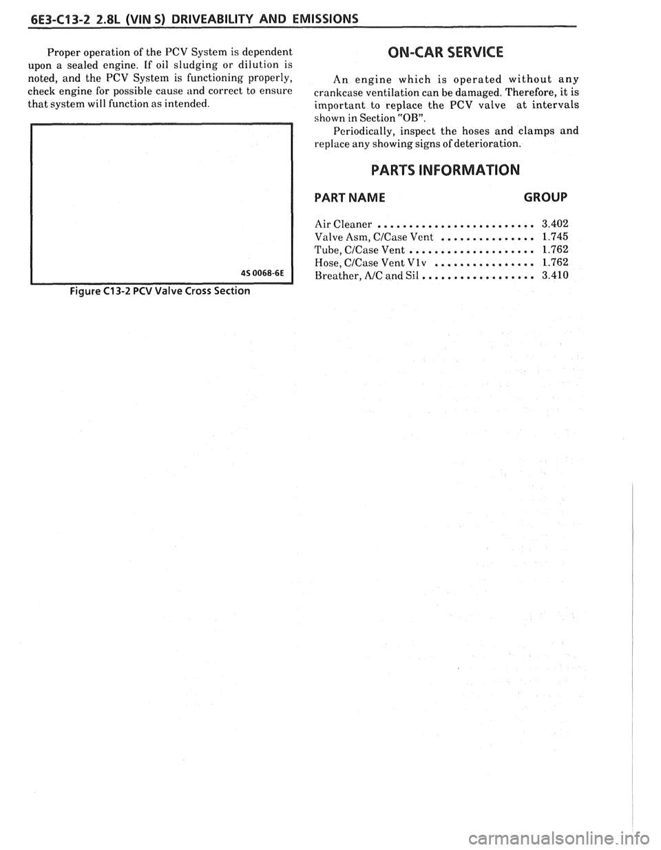
Figure C13-2 PCV Valve Cross Section
......................... Air Cleaner 3.402
............... Valve Asm, C/Case Vent 1.745
.................... Tube, C/Case Vent 1.762
................ Hose, C/Case Vent V 1 v 1.762
.................. Breather, NC and Sil 3.410