1988 PONTIAC FIERO service interval
[x] Cancel search: service intervalPage 957 of 1825
6E3-C13-2 5.OL (VIN F) & 5.7L (VIN 8) DRIVEABILITY AND EMISSIONS
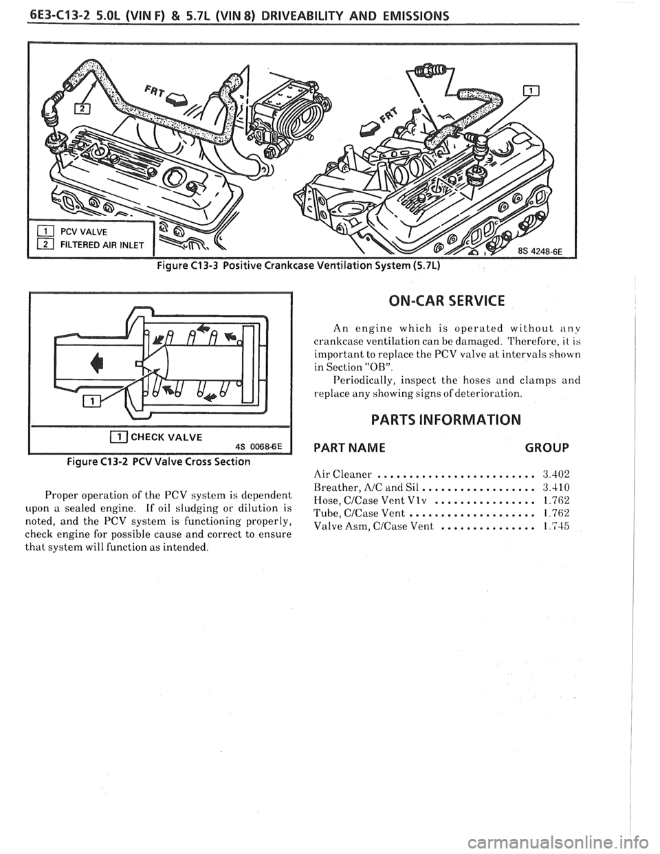
Figure C13-3 Positive Crankcase Ventilation System (5.7L)
CHECK VALVE AS 00686E
Figure C13-2 PCV Valve Cross Section
Proper operation of the PCV system is dependent
upon a sealed engine. If oil sludging or dilution is
noted, and the PCV system is functioning properly,
check engine for possible cause and correct to ensure
that system will function as intended.
ON-CAR SERVICE
An engine which is operated without any
crankcase ventilation can be damaged. Therefore, it is
important to replace the PCV valve at intervals shown
in Section
"OB".
Periodically, inspect the hoses and clamps and
replace any showing signs of deterio~ -a t' lon.
PARTS INFORMATION
PART NAME GROUP
Air Cleaner ......................... 3.402
.................. Breather, NC and Sil 3.410
................ Hose, CICase Vent Vlv 1.762
.................... Tube, CICase Vent 1.762
Valve Asm,
CICase Vent ............... 1.745
Page 1118 of 1825
AUTOMATIC TRANSMISSION 7A-3
PRELIMARY CHECKING PROCEDURE
The condition of an automatic transmission not
operating properly may be influenced by one, or a
combination of the following items:
e Fluid level high/low
(Refer to Section 7A1)
e Engine performance
(Refer to Sections 6 and 6E)
T.V. cable adjustment
(Refer to Section
7A1)
e Manual linkage adjustment
(Refer to Section
7A1)
e Internal fluid leaks
(Refer to Transmission Unit Repair section)
e Electrical system
(Refer to Section 6E and 8A)
e Transmission or other mechanical component
(Refer to Transmission Unit Repair section)
e Vacuum modulator
(Refer to appropriate Hydraulic Diagnosis
Section)
NOISE AND VIBRATION ANALYSIS
A noise or vibration that is noticeable when the
vehicle is in motion, MAY NOT be the result of the
transmission.
If noise or vibration is noticeable in "Park"
(P)
and "Neutral" (N) with engine at idle, but is less
noticeable as
RPM's increase, the cause may be from
poor engine performance.
e Tires for
- Uneven wear
- Imbalance
- Mixed sizes
- Mixed radial and bias ply
(Refer to Section 3E)
e Suspension components for
- Alignment and wear
- Loose fasteners
(Refer to Section 3C)
e Engine/Transmission mounts for
- Damage
- Loose bolts
(Refer
to Sections 6A and 7A2)
e Transmission case mounting holes for:
- Missing bolts, nuts, studs
- Stripped threads
- Cracks
e Flywheel for:
- Missing or loose bolts
- Cracks
- Imbalance
(Refer to Section 6A)
e Torque converter for: - Missing or loose bolts or lugs - Missing or loose balance weights
- Imbalance
TRANSMISSION FLUID LEVEL INFORMATION
Checking fluid level, color and condition at
regular intervals will provide early diagnosis
information about the transmission. This information
may then be used to correct a condition that, if not
detected early, could result in major transmission
repairs.
When adding or changing fluid, use only
DEXRONO 11, or equivalent. Refer to Section OB of
this Service Manual for maintenance information and
servicing intervals.
Fluid level should be checked when it reaches
normal operating temperatures of
190-200°F.
(88-93°C). This temperature is reached after
approximately 15 miles (24 km) of highway
driving.
e Fluid color - Should be dark red (may be dark green)
NOTICE: Do not overfill. Overfilling will cause
foaming, loss of fluid and possible damage to the
transmission.
Inaccurate fluid level readings will result if
checked immediately after the vehicle has been
operated:
- In high abmient temperatures above 90°F
(32°C)
- At sustained high speeds
- In heavy city traffic during hot weather
- As a towing vehicle - In commercial service (taxi or police use)
TRANSMISSION FLUID CHECKING
PROCEDURE
(Refer to Figure 3)
1. Park vehicle on level ground.
2. Apply parking
brake and block wheels.
3. Start
engine and operate vehicle for 15 minutes or
until a normal operating temperature is reached.
4. Move gear
selector through all gear positions.
5. Move
gear selector to "Park" (P).
6. Check fluid level, color and condition.
Page 1683 of 1825
1 H-2 GENERAL INFORMATION - F STYLE
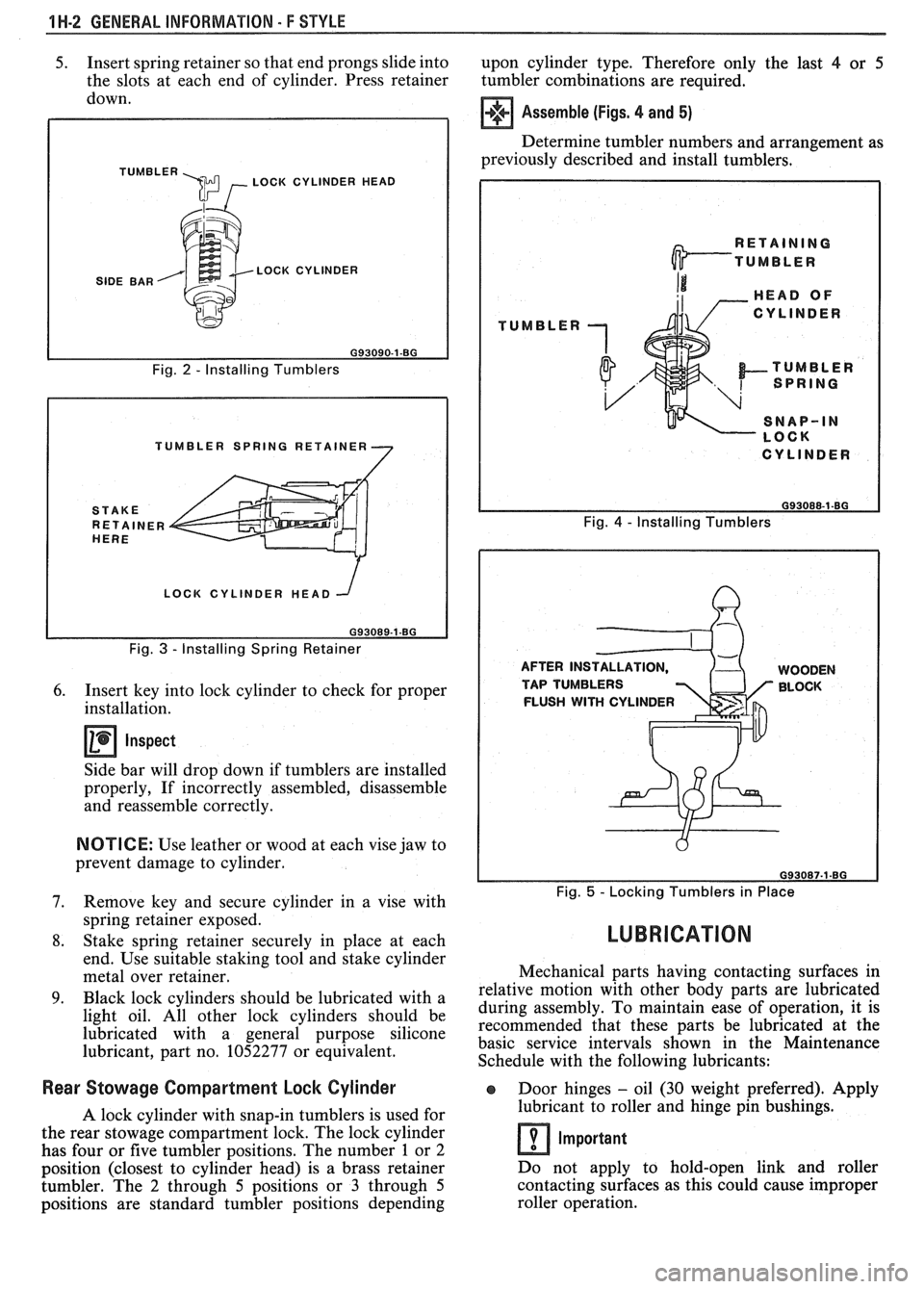
5. Insert spring retainer so that end prongs slide into
upon cylinder type. Therefore only the last 4 or 5
the slots at each end of cylinder. Press retainer
tumbler combinations are required.
down.
TUMBLER \m , LOCK CYLINDER HEAD
SIDE BAR LOCK CYLINDER
Fig.
2 - Installing Tumblers
TUMBLER SPRING RETAINER
LOCK CYLINDER HEAD
Fig.
3 - Installing Spring Retainer
6. Insert key into lock cylinder to check for proper
installation.
Inspect
Side bar will drop down if tumblers are installed
properly, If incorrectly assembled, disassemble
and reassemble correctly.
NOTICE: Use leather or wood at each vise jaw to
prevent damage to cylinder.
7. Remove key and secure cylinder in a vise with
spring retainer exposed.
8. Stake spring retainer securely in place at each
end. Use suitable staking tool and stake cylinder
metal over retainer.
9. Black lock cylinders should be lubricated with a
light oil. All other lock cylinders should be
lubricated with a general purpose silicone
lubricant, part no. 1052277 or equivalent.
Assemble (Figs. 4 and 5)
Determine tumbler numbers and arrangement as
previously described and install tumblers,
TUMBLER
I CYLINDER I
Fig. 4 - Installing Tumblers
AFTER INS WOODEN
TAP TUMBLERS BLOCK
FLUSH
WITH CYLINDER
Fig. 5 - Locking Tumblers in Place
LUBRICATION
Mechanical parts having contacting surfaces in
relative motion with other body parts are lubricated
during assembly. To maintain ease of operation, it is
recommended that these parts be lubricated at the
basic service intervals shown in the Maintenance
Schedule with the following lubricants:
Rear Stowage Compartment Lock Cylinder Door hinges - oil (30 weight preferred). Apply
A lock cylinder with snap-in tumblers is used for lubricant
to roller and hinge pin bushings.
the rear stowage compartment lock. The lock cylinder
Important has four or five tumbler positions. The number 1 or 2
position (closest to cylinder head) is a brass retainer Do
not apply to hold-open link and roller
tumbler. The
2 through 5 positions or 3 through 5 contacting
surfaces as this could cause improper
positions are standard tumbler positions depending roller operation.
Page 1732 of 1825
DOORS - F STYLE 5H-99
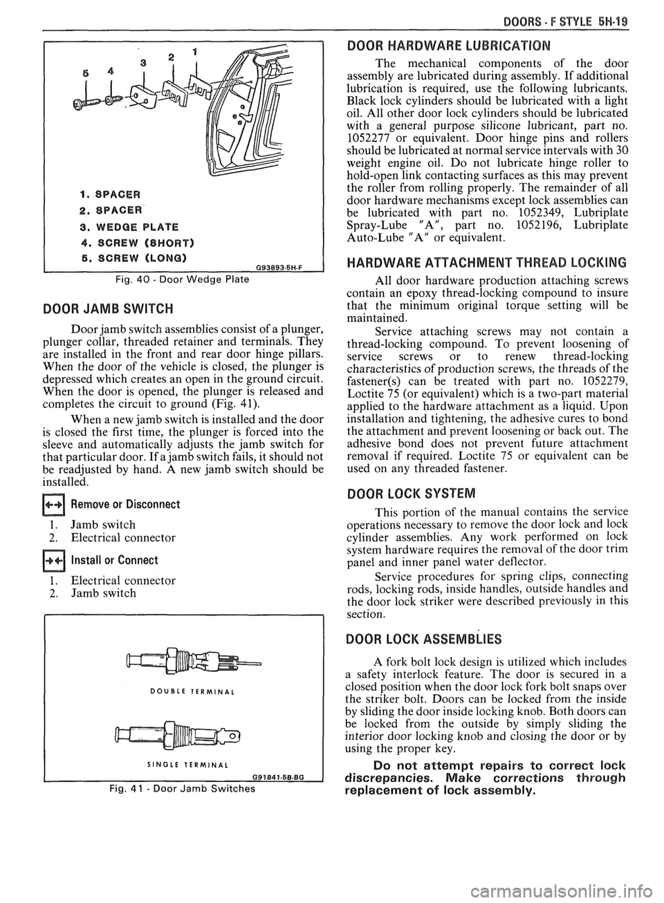
1. SPACER
2. SPACER
3. WEDGE PLATE
4. SCREW (8HORT)
6. SCREW (LONG) G93893.5H-F
Fig. 40 - Door Wedge Plate
DOOR JAMB SWITCH
Door jamb switch assemblies consist of a plunger,
plunger collar, threaded retainer and terminals. They
are installed in the front and rear door hinge pillars.
When the door of the vehicle is closed, the plunger is
depressed which creates an open in the ground circuit.
When the door is opened, the plunger is released and
completes the circuit to ground (Fig. 41).
When a new jamb switch is installed and the door
is closed the first time, the plunger is forced into the
sleeve and automatically adjusts the jamb switch for
that particular door. If a jamb switch fails, it should not
be readjusted by hand. A new jamb switch should be
installed.
Remove or Disconnect
1. Jamb switch
2. Electrical connector
Install or Connect
1. Electrical connector
2. Jamb switch
DOUBLE TERMINAL
I SINGLE TERMINAL I
Fig. 4 1 - Door Jamb Switches
DOOR HARDWARE LUBRICATION
The mechanical components of the door
assembly are lubricated during assembly. If additional
lubrication is required, use the following lubricants.
Black lock cylinders should be lubricated with a light
oil. All other door lock cylinders should be lubricated
with a general purpose silicone lubricant, part no.
1052277 or equivalent. Door hinge pins and rollers
should be lubricated at normal service intervals with 30
weight engine oil. Do not lubricate hinge roller to
hold-open link contacting surfaces as this may prevent
the roller from rolling properly. The remainder of all
door hardware mechanisms except lock assemblies can
be lubricated with part no. 1052349, Lubriplate
Spray-Lube "A", part no. 1052196, Lubriplate
Auto-Lube "A" or equivalent.
HARDWARE ATTACHMENT THREAD LOCKING
All door hardware production attaching screws
contain an epoxy thread-locking compound to insure
that the minimum original torque setting will be
maintained.
Service attaching screws may not contain a
thread-locking compound. To prevent loosening of
service screws or to renew thread-locking
characteristics of production screws, the threads of the
fastener(s) can be treated with part no. 1052279,
Loctite 75 (or equivalent) which is a two-part material
applied to the hardware attachment as a liquid. Upon
installation and tightening, the adhesive cures to bond
the attachment and prevent loosening or back out. The
adhesive bond does not prevent future attachment
removal if required. Loctite 75 or equivalent can be
used on any threaded fastener.
DOOR LOCK SYSTEM
This portion of the manual contains the service
operations necessary to remove the door lock and lock
cylinder assemblies. Any work performed on lock
system hardware requires the removal of the door trim
panel and inner panel water deflector.
Service procedures for spring clips, connecting
rods, locking rods, inside handles, outside handles and
the door lock striker were described previously in this
section.
DOOR LOCK ASSEMBLIES
A fork bolt lock design is utilized which includes
a safety interlock feature. The door is secured in a
closed position when the door lock fork bolt snaps over
the striker bolt. Doors can be locked from the inside
by sliding the door inside locking knob. Both doors can
be locked from the outside by simply sliding the
interior door locking knob and closing the door or by
using the proper key.
Do not attempt repairs to correct lock
discrepancies. Make corrections through
replacement of lock assembly.
Page 1784 of 1825
SEATS - F STYLE 9H-1
SEC"IC"0N 9H
SEATS
NOTICE: Lap belt to floor pan and shoulder belt to roof panel or quarter panel fasteners are important
attaching parts in that they could affect the performance of vital parts and systems, and/or could result in major
repair expense. They must be replaced with one of the same part number or with an equivalent part if replacement
becomes necessary. Do not use a replacement part of lesser quality or substitute design. Torque values must be
used as specified during reassembly to assure proper retention of these parts.
CONTENTS
Restraint Systems ........................................... 9H- 1
Lap and Shoulder Belts
............................... 9H-1
Comfort Lock Operational Checks
and Requirements
.................................... 9H- 1
Front Seat Shoulder Belt Retractor
............ 9H-2
Child Seat
...................................................... 9H-2
............................... .................. -.rant Seats .. 9H-5
Mead Restraint
............................................. 9H-5
Reclining
Seatback ................................... 9H-6
Front
Seatback ........................................... 9H-7
Inertia Lock Check
...................................... 9H-7
............................... Manual Recliner Check 9H-7
........................... Seat Torque Specifications 9H-8
Manual Seat
- Diagnosis Chart ................... 9H-8
..................... Power Seat - Diagnosis Chart 9H-9
RESTRAINT SYSTEMS
LAP
AND SHOULDER BELTS
The front seat belts incorporate a 4-to-8 second
fasten seat belt reminder lamp and sound signal
designed to remind the driver if the lap and shoulder
belts are not fastened when the ignition is turned to the
on position. If the driver's seat belt
is buckled, the
alarm will not operate; however, the fasten seat belt
xminder lamp will stay on for a 4-to-8 second period.
,, the driver's seat belt is not buckled, the reminder
lamp and sound signal will automatically shut off after
the 4-to-8 second interval. To diagnose a system
failure, refer to Seat Belt Reminder
Lamp/Alarm
Diagnosis in Section 8A.
The shoulder belt is attached to the front seat lap
belt latch plate and connected to an inertia locking
retractor installed to the roof panel above the right and
left side of the front seat. The shoulder belt remains
unlocked to allow the occupants to move freely while
the vehicle is being operated. When the vehicle
decelerates or changes direction abruptly, the shoulder
belt is locked in position by a pendulum that causes a
locking bar to engage a cog of the retractor mechanism.
The retractor has a comfort lock feature that
allows the occupant to adjust the shoulder belt for
proper fit and comfort. When engaged, the comfort
lock prevents full retraction of the webbing to eliminate
occupant discomfort due to webbing load on the
shoulder. The occupant can readjust the comfort lock
during vehicle operation as described below.
When servicing or replacing lap and shoulder
belts, refer to the following precautionary items: Front
Seat Adjustments
............................... 9H- 10
Manual Seat Control Arm Knob
................ 9H-10
Front Seat Assembly
.................................... 9H- 1 1
Seat Adjuster Assembly ............................. 9H-11
Six-way Seat Adjuster .................................. 9H- 12
Power Seat Switch
........................................ 9H-15
Four-way Manual Seat Adjuster
................. 9H-15
Seatback Lock Striker/Side Bar Stop .......... 9H-15
High Performance AQ9 Seat
(2FS87) ......... 9H-15
................. .................................... Rear Seats ... 9H- 19
........................................ Cushion Assembly 9H- 19
................................ Folding Rear Seatback 9H- 19
........................... Seatback Lock Assembly 9H-20
.................................. Seatback Lock Striker 9H-20
1. Lap and shoulder belts will be serviced as follows:
a. Retractor
portion(s) of
front seat lap and
shoulder belt for outboard passenger and
driver.
b. Buckle portion of front seat lap belt for
outboard passenger and driver.
c. All belts other than those mentioned in
above steps a and b will be serviced in
complete sets.
d. Do not intermix standard and deluxe belts
on front or rear seats.
2. Keep sharp edges and damaging objects away
from belts.
3. Avoid bending or damaging any portion of the
belt buckle or latch plate.
4. Do not bleach or dye belt webbing (clean with a
mild soap solution and water).
5. When installing lap or shoulder belt anchor bolt,
start bolt by hand to assure that bolt is threaded
straight.
NOTICE: See NOTICE on page 9H-1 of this
section.
6. Do not attempt repairs on lap or shoulder belt
retractor mechanisms or lap belt retractor covers.
Replace with new service replacement parts.
Comfort Lock Operational Checks and Requirements
The shoulder belt comfort lock feature must
function as follows:
1. Extend the webbing from the retractor to a
distance approximating buckled position.