1988 PONTIAC FIERO audio
[x] Cancel search: audioPage 1394 of 1825
WARNINGS AND ALARMS: CHIMES
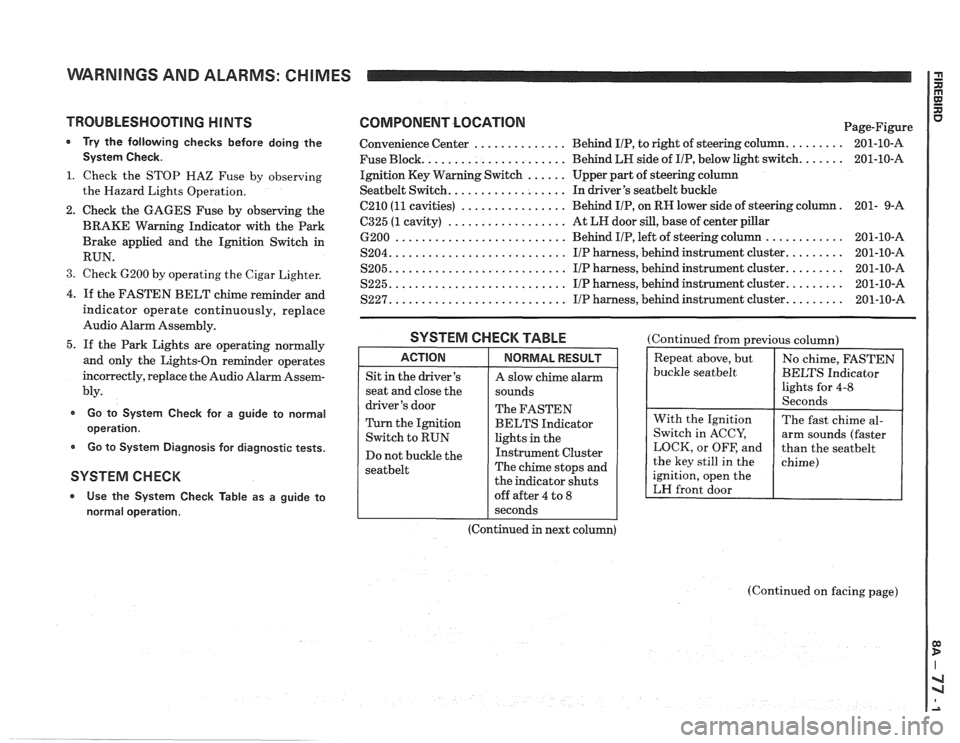
TROUBLESHOOTING H lNTS
* Try the following checks before doing the
System Check.
1. Check the STOP HAZ Fuse by observing
the Hazard Lights Operation.
2. Check the GAGES Fuse by observing the
BRAKE Warning Indicator with the Park
Brake applied and the Ignition Switch in
RUN.
3. Check 6200 by operating the Cigar Lighter.
4. If the FASTEN BELT chime reminder and
indicator operate continuously, replace
Audio Alarm Assembly.
5. If the Park Lights are operating normally
and only the Lights-On reminder operates
incorrectly, replace the Audio Alarm Assem-
bly.
Go to System Check for a guide to normal
operation.
Go to System Diagnosis for diagnostic tests.
SYSTEM CHECK
* Use the System Check Table as a guide to
normal operation.
COMPONENT LOCATlON Page-Figure
Convenience Center
.............. Behind IIP, to right of steering column. ........ 201-10-A
Fuse Block.
..................... Behind LH side of IIP, below light switch. ...... 201-10-A
Ignition Key Warning Switch
...... Upper part of steering column
Seatbelt Switch. ................. In driver's seatbelt buckle
C210
(11 cavities) ................ Behind IIP, on RH lower side of steering column. 201-
9-A
6325 (1 cavity) .................. At LH door sill, base of center pillar
6200 .......................... Behind IIP, left of steering column ............ 201-10-A
S204. .......................... IIP harness, behind instrument cluster. ........ 201-10-A
S205. .......................... IIP harness, behind instrument cluster. ........ 201-10-A
S225. .......................... I/P harness, behind instrument cluster. ........ 201-10-A
S227. .......................... IIP harness, behind instrument cluster. ........ 201-10-A
SYSTEM CHECK TABLE
ACTION
Sit in the driver's
seat and close the
driver's door
Turn the Ignition
Switch to RUN
Do not buckle the
seatbelt
NORMAL RESULT
A slow chime alarm
sounds
The FASTEN
BELTS Indicator
lights in the
Instrument Cluster
The chime stops and
the indicator shuts
off after 4 to
8
(Continued from previous column)
buckle
seatbelt
ignition, open the
LH front door
I seconds
(Continued in next column)
(Continued on facing page)
Page 1395 of 1825
WARNINGS AND ALARMS: CHIMES I
(Continued from facing page) (Continued from previous column) B: KEY IN IGNITION INPUT TEST
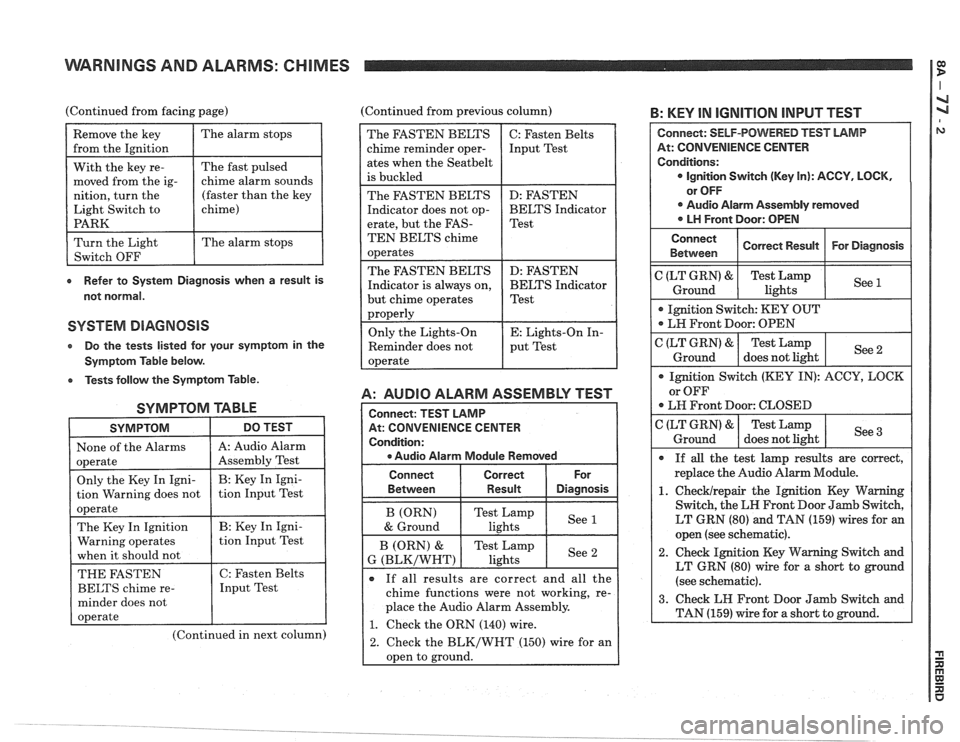
e Refer to System Diagnosis when a result is
not normal.
SYSTEM DIAGNOSIS
Do the tests listed lor your symptom in the
Symptom Table below.
e Tests follow the Symptom Table.
SYMPTOM TABLE
SYMPTOM DO TEST I
1 None of the Alarms 1 A: Audio Alarm I
(Continued in next column)
A: AUDIO ALARM ASSEMBLY TEST
At: CONVENIENCE CENTER
e Audio Alarm Module Removed
The FASTEN BELTS
chime reminder oper-
ates when the
Seatbelt
is buckled
The FASTEN BELTS
Indicator does not op-
erate, but the
FAS-
TEN BELTS chime
operates
The FASTEN BELTS
Indicator is always on,
but chime operates
properly
Only the Lights-On
Reminder does not
operate
Connect Correct
Between
I Result Diasnosis
C: Fasten Belts
Input Test
D: FASTEN
BELTS Indicator
Test
D: FASTEN
BELTS Indicator
Test
E: Lights-On In-
put Test
If all results are correct and all the
chime functions were not working, re-
place the Audio Alarm Assembly.
1. Check the ORN (140) wire.
2. Check the BLK/WHT (150) wire for an
oDen to ground.
At: CONVENIENCE CENTER
LT GRN (80) and TAN (159) wires for an
open (see schematic).
2. Check Ignition Key Warning Switch and
LT GRN (80) wire for a short to ground
(see schematic).
Page 1396 of 1825
WARNINGS AND ALARMS: CHIMES
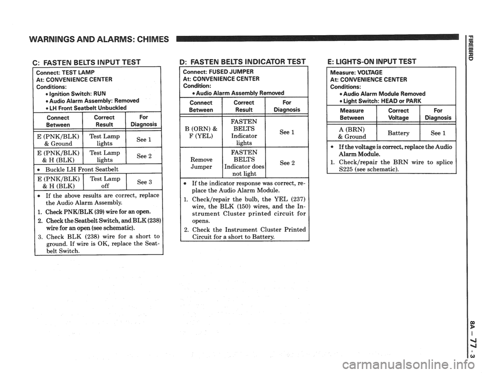
6: FASTEN BELTS INPUT TEST
At: CONVENIENCE CENTER
Ignition Switch: RUN
If the above results are correct, replace
the Audio Alarm Assembly.
Buckle
LH Front
Seatbelt
1. Check PNKIBLK (39) wire for an open.
2. Check the Seatbelt Switch, and BLK (238)
wire for an open (see schematic).
3. Check BLK (238) wire for a short to
ground. If wire is OK, replace the
Seat-
4: FASTEN BELTS INDICATOR TEST
See E (PNKIBLK)
& H (BLK)
Connect: FUSED JUMPER
At: CONVENIENCE CENTER
Condition:
a Audio Alarm Assembly Removed
Connect Correct For
Between Result Diagnosis
Test Lamp
off If
the indicator response was correct, re-
place the Audio Alarm Module.
1. Checklrepair the bulb, the YEL (237)
wire, the BLK (150) wires, and the In-
strument Cluster printed circuit for
opens.
2. Check the Instrument Cluster Printed
Circuit for
a short to Battery.
E: LIGHTS-ON INPUT TEST
At: CONVENIENCE CENTER
0 Audio Alarm Module Removed
Page 1397 of 1825
WARNINGS AND ALARMS: CHIMES
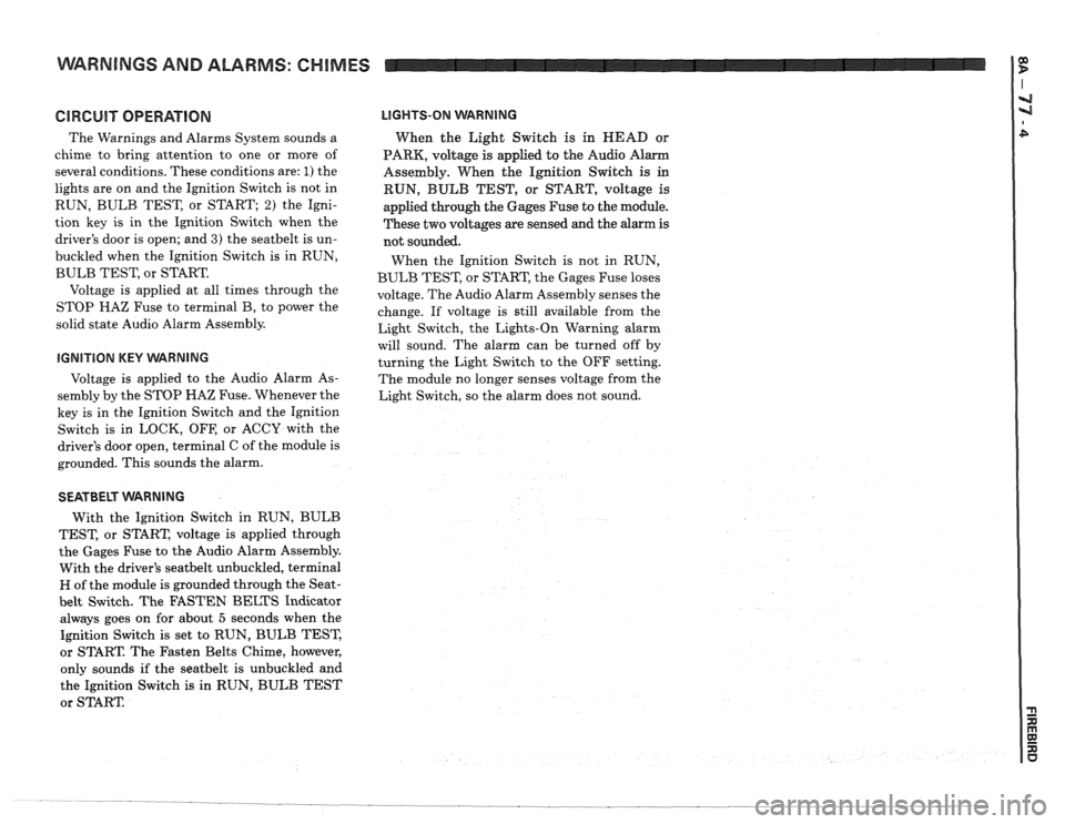
GlRGUlT OPERATION
The Warnings and Alarms System sounds a
chime to bring attention to one or more of
several conditions. These conditions are:
1) the
lights are on and the Ignition Switch is not in
RUN, BULB TEST, or START;
2) the Igni-
tion key is in the Ignition Switch when the
driver's door is open; and
3) the seatbelt is un-
buckled when the Ignition Switch is in RUN,
BULB TEST, or START.
Voltage is applied at all times through the
STOP
HAZ Fuse to terminal B, to power the
solid state Audio Alarm Assembly.
IGNITION KEY VVARNING
Voltage is applied to the Audio Alarm As-
sembly by the STOP HAZ Fuse. Whenever the
key is in the Ignition Switch and the Ignition
Switch is in LOCK, OFF, or ACCY with the
driver's door open, terminal C of the module is
grounded. This sounds the alarm.
LIGHTS-ON WARNING
When the Light Switch is in HEAD or
PARK, voltage
is applied to the Audio Alarm
Assembly. When the Ignition Switch
is in
RUN, BULB TEST, or START, voltage is
applied through the Gages Fuse to the module.
These two voltages are sensed and the alarm is
not sounded.
When the Ignition Switch is not in RUN,
BULB TEST, or START, the Gages Fuse loses
voltage. The Audio Alarm Assembly senses the
change. If voltage is still available from the
Light Switch, the Lights-On Warning alarm
will sound. The alarm can be turned off by
turning the Light Switch to the OFF setting.
The module no longer senses voltage from the
Light Switch, so the alarm does not sound.
SEATBELT WARNING
With the Ignition Switch in RUN, BULB
TEST, or START, voltage is applied through
the Gages Fuse to the Audio Alarm Assembly.
With the driver's
seatbelt unbuckled, terminal
H of the module is grounded through the Seat-
belt Switch. The FASTEN BELTS Indicator
always goes on for about
5 seconds when the
Ignition Switch is set to RUN, BULB TEST,
or START. The Fasten Belts Chime, however,
only sounds if the
seatbelt is unbuckled and
the Ignition Switch
is in RUN, BULB TEST
or START
Page 1422 of 1825
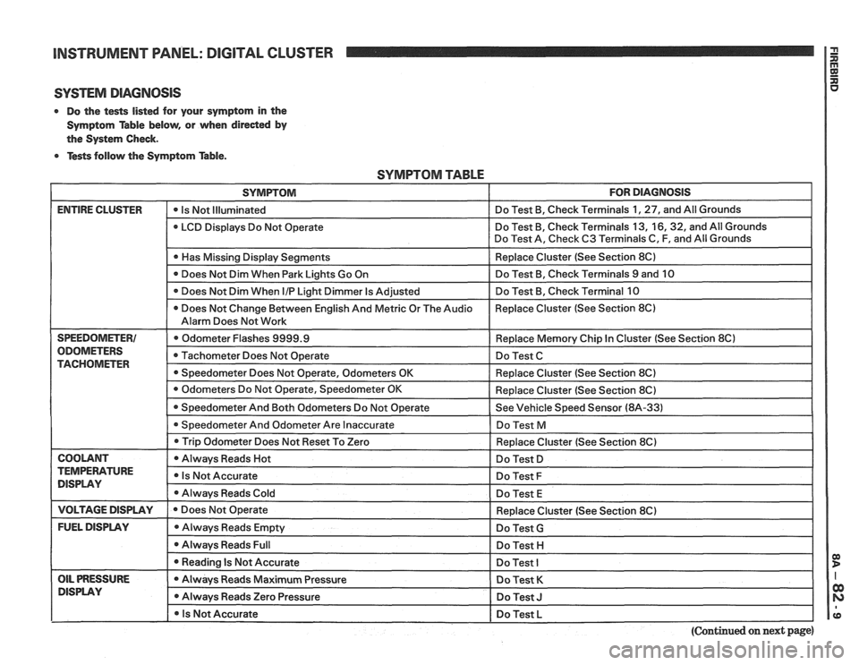
INSTRUMENT PANEL: DlGlTAL CLUSTER a
SYSTEM DIAGNOSIS
0 Do the tests listed for your symptom in the
Symptom Table below, or when
direded by
the System Check.
0 Tests follow the Symptom Table.
SYMPTOM TABLE
SYMPTOM FOR DIAGNOSIS
ENTIRE CLUSTER - -
0 Is Not Illuminated Do
Test B, Check Terminals 1, 27, and All Grounds
LCD Displays Do Not Operate Do
Test B, Check Terminals 13,
16,32, and All Grounds
Do Test A, Check C3 Terminals C, F, and All Grounds
I 0 Has Missing Display Senments I Replace Cluster (See Section 8C) I
Does Not Dim When Park Lights Go On Do
Test B, Check Terminals 9 and 10
Does Not Dim When
I/P Light Dimmer Is Adjusted Do
Test B, Check Terminal 10
0 Does Not Change Between English And Metric Or The Audio Replace
Cluster (See Section 8C)
Alarm Does Not Work
SPEEDOMETER1 Odometer Flashes 9999.9 Replace Memory Chip In Cluster (See Section 8Cl
ODOMETERS Tachometer Does Not Operate Do Test C TACHOMETER 0 Speedometer Does Not Operate, Odometers OK Replace Cluster (See Section 8C)
I 0 Trip Odometer Does ~otReset To Zero I Redace Cluster (See Section 8C) I
I COOLANT I 0 Always Reads Hot I Do Test D I
TEMPERATURE Is Not Accurate DISPLAY Do Test F
Always Reads Cold
Do Test E
I VOLTAGE DISPLAY I e Does Not Operate
FUEL DISPLAY Always Reads Empty
0 Always Reads Full
I 0 Reading Is Not Accurate - --
OIL PRESSURE Always Reads Maximum Pressure
DlSPLAV 0 Always Reads Zero Pressure
I 0 Is Not Accurate Replace
Cluster (See Section 8C)
Do Test
G
Do Test H I
Do Test I
Do Test K
Do Test J I
Do Test L I pp
(Continued on next page)
Page 1542 of 1825
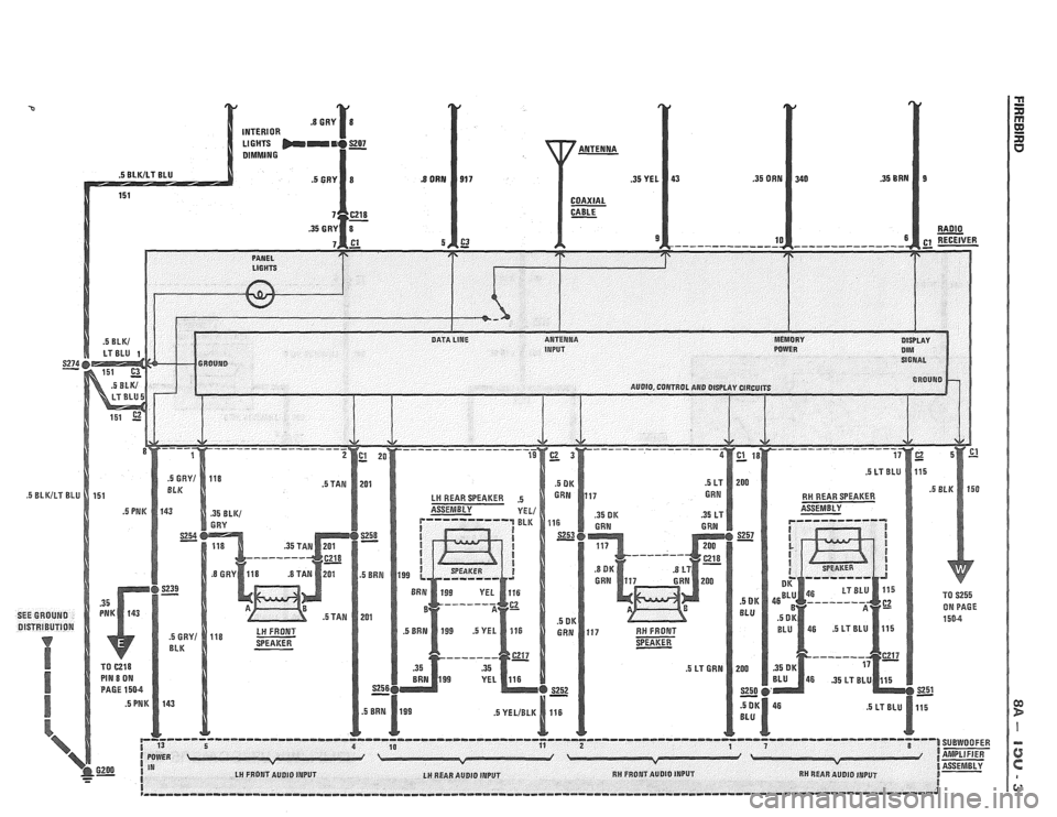
p------------o--------o------------------------------------------------------------------------------- 1 '3 5 4 1 SUEWOOFER
( POWER I IA- v I- 6200 1 IN l ASSEMBLY - - I LH FROPJT AUDIO INPUT LH REAR AUDIO INPUT RH FRONT AUDIO INPUT RH REAR AUDIO INPUT B- I I ,,--,,,-,-,,-,-,-,----~--------------------------~---------------------------------------------------J
Page 1556 of 1825
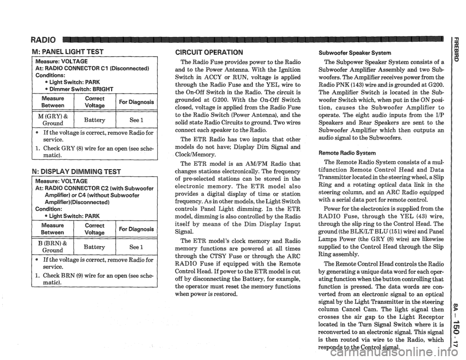
M: WNEL LIGHT TEST GlRGUlT OPERATION Subwoofer Speaker System
TOR 61 (Disconnected)
If the voltage is correct, remove Radio for
N: DISPLAY DIMMING TEST
TOW 62 (with Subwoofer
The Radio Fuse provides power to the Radio
and to the Power Antenna. With the Ignition
Switch in ACCY or RUN, voltage is applied
through the Radio Fuse and the
UEL wire to
the On-Off Switch in the Radio. The circuit is
grounded at 6200. With the On-Off Switch
closed, voltage is applied from the Radio Fuse
to the Radio Switch (Power Antenna), and the
solid state Radio Circuits to ground. Two wires
connect each speaker to the Radio.
The ETR Radio has two inputs that other
models do not have; Display Dim Signal and
ClocklMemory.
The ETR model is an AMIFM Radio that
changes stations electronically. The frequency
of pre-selected stations can be stored
in the
electronic memory. The ETR model also
provides a digital display of time or station
frequency. As in other models, the Light Switch
controls Panel Light dimming. In the
ETR
model, g is also controlled by the Radio
itself by means of the Dim Display Input
Signal.
The ETR model's clock memory and Radio
memory functions are powered at all times
through the CTSY Fuse or through the ARC
RADIO Fuse if equipped with the Remote
Control Head. If power to the ETR model is cut
off by disconnecting the Battery, for example,
the operator must reset the memory functions
when power is restored. The
Subpower Speaker
System consists of a
Subwoofer Amplifier Assembly and two Sub-
woofers. The Amplifier receives power from the
Radio PNK
(143) wire and is grounded at 6200.
The Amplifier Switch is located in the
Sub-
woofer Switch which, when put in the ON posi-
tion, causes the Subwoofer Amplifier to
operate. The eight audio inputs from the
I/P
Speakers and Rear Speakers are sent to the
Subwoofer Amplifier which then outputs an
audio signal to the Subwoofers.
Remote Radio System
The Remote Radio System consists of a mul-
tifunction Remote Control
Head and Data
Transmitter located in the steering wheel, a Slip
Ring and a rotating optical data link in the
steering
colurnn, and an ARC Radio equipped
with a serial data port for remote control.
Power for the electronics is supplied from the
RADIO Fuse, through the
YEL (43) wire,
through the slip ring to the Control Head. The
ground (the
BLKLT BLU (15 1) wire) and Pand
Larnps Power (the GRY (8) wire) are Likewise
supplied to the Control Head through the Slip
Ring assembly.
The Remote Control Head controls the Radio
by generating a unique data word for each oper-
ating function when the button controlling that
function is pressed. The data words are con-
verted from an electronic signal to an optical
signal by the Light Transmitter in the steering
column Cancel Cam. The light signal then
crosses the air gap to the Light Receptor
located in the
Turn Signal Switch where it is
reconverted to
an electronic signal. This signal
is then routed via wire to the Radio, which
responds to the Control signal.
Page 1650 of 1825
RADIO SYSTEMS AND ANTENNAS 9A-1
SECTION 9A
0 SYSTEMS AND ANTENNAS
CONTENTS
............................................. General Description .................................... 9A-1 Radio Operation 9A-4
Radio
............................................................ 9A-1 ETR AM/FM Stereo (UM-7) ....................... 9A-4
Antennas
........................................................ 9A- 1 ETR Stereo Cassette (UM-6) ......................... 9A-5
Fixed Antenna
.......................................... 9A- 1 ETR Stereo/Cassette/Eaualizer
Diagnosis ........................................................
Radio ....................... .. ................................
Static and Noise .................................... .....
........................................ Popping Noise
Preliminary Diagnostics
.............................
Antenna ................................. .. ................
Tape Player .................. .... .......................
Service Procedures ....................................
Radio and Speakers ........................... .............
Radio Noise Suppression Equipment ............
Stereo Cassette Tape Player ..........................
Tape & Tape Player Care ........................
(UX-1) ..................................................... 9A-6
Advanced ETR
Stereo/Cassette/Equalizer Touch
Control
.................................... ... .............. 9A-7
On-Car Service .............................................. 9A-9
Radio Receiver
............................................ 9A-9
Radio Steering Wheel Controls
..................... 9A-9
Audio Amplifier
........................................... 9A-9
Radio Suppression
..................................... 9A-9
Front Speaker
................................................. 9A-9
............... Rear Speaker; Sub Woofer Speaker
9A-9
Antenna
..................... .. ............................. 9A- 10
GENERAL DESCRIPUION
RADIO ANTENNAS
For radios and radio use see the "Radio Fixed Antenna
Operation" section. ETR means 'Electronically Tuned The
fixed antenna on the right front fender
Receiver'. cannot be adjusted up or down. It may provide
improved reception in rural areas.
- The fixed antenna is designed to withstand most
car washes without damage. If the antenna becomes
slightly bent, you can straighten it by hand. The
antenna can be replaced if severely bent (by vandalism,
etc.). Antennas must be kept clean for good
performance.
RADIO
Because radio problems are normally repaired at
authorized warranty repair stations, the tendency is to
remove the set when a problem is reported, without any
preliminary diagnosis. This results in a large number
of radios being "No Trouble Found" units when
received by the warranty repair stations. Often the
trouble can be corrected without radio removal. wire.
If equipped with
A/C, the blower motor has a
built-in capacitor. Extra electrical equipment added to
the static if not properly grounded or wiring was
improperly routed.
Weak
FM station reception will be affected by
nearby buildings, car speed and direction. These
"flutter" and "fading" conditions are characteristic of
weak FM signals.
ETR radios require clock and button reset if the
battery is disconnected.
Popping Noise
Static and Noise Operating devices such as turn signals, pushing in
cigarette lighter, operating stop lights, etc., may cause
Ground strap connections must be clean and
a popping noise on distant (weak) AM signals.
tight, spark plug cables must be TVRS type and in
good condition and resistance-type spark plugs used.
Preliminary Diagnostics
Capacitors are used in the generator, heating/air
conditioning system, and fuse panel to reduce noise
The inconvenience of driving without a radio
entering the radio through the feed wires. If the car has
while the set is being serviced can often be avoided if
a heater only, the capacitor is in the blower motor feed
the following quick checks are used to eliminate