1988 PONTIAC FIERO warning light
[x] Cancel search: warning lightPage 20 of 1825
F CARLINE
ITEM 10
TransmissionRransaxle Service
The manual transmission or transaxle fluid does not
require changing. (Corvette only.) Change fluid in over-
drive unit every 30,000 miles (50 000 km).
For automatic transmissions or transaxles, change
both the fluid and filter every 15,000 miles (25 000 km) if
the car is mainly driven under one or more of these
conditions:
@ In heavy city traffic where the outside temperature
regularly reaches 90°F (32°C) or higher.
@ In hilly or mountainous terrain.
@ Frequent trailer pulling.
@ Uses such as found in taxi, police car or delivery
service.
If you do not use your car under any of these condi-
tions, change both the fluid and filter every 100,000 miles
(160 000 km). See you Owner's Manual for further
details.
ITEM 11
Spark Plug Service*
Replace spark plugs with type listed in your Owner's
Manual.
ITEM 12
Spark Plug Wire Inspection*
Clean wires and inspect for burns, cracks or other dam-
age. Check the wire boot fit at distributor and at spark plugs.
Replace wires as needed.
ITEM 13
Positive Crankcase Ventilation (PCV) Valve
Inspection*
Inspect valve for proper function. Replace valve if
necessary as well as any worn, plugged or collapsed
hoses.
ITEM 14
EGR System Service*
Conduct EGR System Service as referenced in the
EGR System Chart shown in the appropriate 6E Section.
Also, refer to your GM maintenance schedule booklet for
specific applications.
ITEM 15
Air Cleaner and PCV Filter Replacement*
On 1.6 and 2.0 liter engines, replace every 50,000
miles (80 000 km). On all other engines, replace every
30,000 miles (50 000 km). Replace more often under
dusty conditions. Ask your dealer for the proper replace-
ment interval for your driving conditions.
MAINTENANCE AND LUBRICATION 08-3
ITEM 16
Engine Timing Check*
Adjust timing to underhood label specifications. If
no specifications are shown, no adjustment is needed.
ITEM 17
Fuel Tank, Cap and Lines Inspection*
Inspect fuel tank, cap and lines (including fuel rails
and injection assembly, if so equipped) for damage or
leaks. Inspect fuel cap gasket for an even filler neck
imprint or any damage. Replace parts as needed.
ITEM 18
Thermostatically Controlled Air Cleaner
Inspection*
If your car is equipped, inspect all hoses and ducts
for proper hookup. Make sure valve works properly.
OWNER INSPECTIONS AND SERVICES
Listed below are inspections and services which
should be made by either you or a qualified technician at
the intervals shown to help ensure proper safety, emission
performance and dependability of your car. Take any
problems promptly to your dealer or another qualified
technician for service advice. Whenever repairs are neces-
sary, have them completed at once. For your safety and
that of others, any safety-related parts that could have
been damaged in an accident should be inspected and all
needed repairs should be done before operating your car.
Be sure to use the proper fluids and lubricants as shown in
Figure OB-2.
WHILE OPERATING YOUR VEHICLE
Automatic transmissionltransaxle shift indi-
cator operation - Make sure the indicator points to the
gear chosen.
Horn operation - Blow the horn occasionally to
make sure it works. Check all button locations.
I
Brake system operation -- Be alert to abnormal
sounds, increased brake pedal travel or repeated pulling to
one side when braking. Also, if a brake warning light
comes on or flashes, or the anti-lock warning light (if
equipped) comes on or remains on, something may be
wrong with part of the brake system. Have it inspected and
repaired at once.
Exhaust system operation - Be alert to any
changes in the sound of the system or any smell of fumes.
These are signs the system may be leaking or overheating.
.
Have it inspected and repaired at once. Also see "Engine
Exhaust Gas Caution (Carbon Monoxide)" and "Catalytic
Converter" in your Owner's Manual.
*An Emission Control Service
Page 21 of 1825
OB-4 MAINTENANCE AND LUBRICATION
Tire and wheel operation - Be alert to a vibra-
tion of the steering wheel or seat at normal highway
speeds. This may mean a wheel balance is needed. Also, a
pull right or left on a straight, level road may show the
need for
a tire pressure adjustment or wheel alignment.
Steering system operation - Be alert to
changes in steering action. An inspection is needed when
the steering wheel is harder to turn or has too much free
play or if unusual sounds are noted when turning or
parking.
Headlight aim operation - Take note of light
pattern occasionally. If beam aim doesn't look right,
headlights should be adjusted.
AT EACH FUEL FILL
Engine oil level check - Check engine oil level
and add if necessary. See your Owner's
Manual for further
details.
NOTICE: A large loss in this system may indicate a
problem. Have it inspected and repaired at once.
Engine coolant level and condition - Check
engine coolant level in coolant reservoir tank and add if
necessary. Replace if dirty or rusty. See your Owner's
Manual for further details.
NOTICE: A large loss in this system may indicate a
problem. Have it inspected and repaired at once.
Windshield washer fluid level check -- Check
washer fluid level in container and add if necessary.
Hood latch operation - When opening hood on
cars equipped with hoods that open from the front, note
the operation of secondary latch. It should keep hood from
opening all the way when primary latch is released. Make
sure that hood closes firmly.
AT LEAST MONTI-ILY
Tire and wheel inspection and pressure
check--
Check tires for abnormal wear or damage. Also,
check for damaged wheels. Keep pressures as shown on
Tire Placard on the driver's door (include spare unless it is
a stowaway). Pressure should b\: checked when tires are
"cold". See "Tires" in Owner's Manual for further
infomation.
Light operation check - Check operation of
license plate light, side-marker lights, headlights includ-
ing high beams, parking lights, taillights, brake lights.
turn signals, backup lights, instrument panel and interior
lights and hazard warning flashers.
Fluid leak check - After the car has been parked
for a while, inspect the surface beneath the car for water,
oil, fuel or other fluids. Water dripping from the air
conditioning system after use is normal. If you notice fuel
leaks or fumes, the cause should be found and corrected at
once.
AT LEAST TWICE A YEAR (FOR EXAMPLE,
EVERY SPRING AND FALL)
Power steering pump fluid level check --
Check power steering pump fluid level in accordance with
Owner's Manual instructions and keep at proper level.
NOTICE: A large loss in this system may indicate a
problem. Have it inspected and repaired at once.
Brake master cylinder reservoir fluid level
check ---- Check fluid and keep at proper level. Note: It is
normal for the brake fluid level to go down slightly as the
brake pads wear
- so be sure to keep reservoir filled.
NOTICE: A large loss in this system may indicate a
problem. Have
it inspected and repaired at once.
Clutch system service --- manual transmis-
sionltransaxle --- For cars equipped with hydraulic
clutch system, check the reservoir fluid level and add fluid
as required. All others, check clutch pedal free travel and
adjust as necessary. See your Owner's Manual for further
details.
~
NOTICE: A large loss in this system may indicate a
problem. Have it inspected and repaired at once.
Weatherstrip Lubrication - Clean surface and
then apply a thin film of silicone grease with a clean cloth.
EACH TIME OIL IS CHANGED
Automatic and manual transmissionltrans-
axle fluid level check - Check transmission/transaxle
fluid level and add as required. (Corvette only) if equipped
with manual transmission
- check fluid in the overdrive
unit and add as required.
NOTICE: A large loss in this system may indicate a
problem. Have
it inspected and repaired at once.
Brake systems inspection - For convenience,
the following should be done when wheels are removed
for rotation: Inspect lines and hoses for proper hookup,
binding, leaks, cracks, chafing, etc. Inspect disc brake
pads for wear and rotors for surface condition. Also in-
spect drum brake linings for wear and cracks. Inspect
other brake parts, including drums, wheel cylinders, park-
ing brake, etc. at the same time. Check parking brake
adjustment.
INSPECT BRAKES MORE OFTEN IF DRIVING
HABITS OR CONDITIONS RESULT IN FREQUENT
BRAKING.
Steering, suspension and front drive axle
boot and seal inspection
- Inspect front and rear
suspension and steering system for damaged, loose or
missing parts, signs of wear or lack of lubrication. Inspect
power steering lines and hoses for proper hookup, bind-
ing, leaks, cracks, chafing, etc. (On cars equipped with
manual steering gear, check for seal leakage.) On
front-
wheel-drive cars, clean then inspect drive axle boot seals
for damage, tears or leakage. Replace seals if necessary.
Exhaust system inspection - Inspect complete
system. Inspect body near the exhaust system. Look for
broken, damaged, missing or out-of-position parts as well
as open seams, holes, loose connections or other condi-
tions which could cause a heat buildup in the tloor pan or
could let exhaust fumes seep into the trunk or passenger
compartment.
Page 111 of 1825
2C-4 CHASSIS SHEET METAL
3. Clean area to be repaired.
4. Mix and apply the repair material by using a
putty knife or rubber squeegee.
5. Work the material into the repair and build up
the desired contour. For deep filling, and on
vertical surfaces, several layers may be
required.
6. Feather-sand damaged area with No. 200 sand-
paper and finish-sand with No. 320 sandpaper.
7. Prepare repaired area for refinishing. Refinish
with acrylic lacquer as described below.
1. THOROUGHLY CLEAN the entire surface
area, using Naphtha or equivalent solvent, to
insure a surface free of contamination.
2. To promote paint adhesion, a light scuff-sand-
ing of the surface with
#400-grit sandpaper is
recommended.
3. Repeat cleaning of the surface.
4. Color coat with acrylic lacquer for proper color
match.
5. Allow to dry thoroughly, rub out and polish.
PAINT REFINISHING PROCEDURES FOR
URETHANE, P.V.C. AND T.P.R. SURFACES
Urethane material will withstand minor impact
and the resultant damage, such as occurs in parking
lots, by recovering its original shape. Its Endura paint
film responds to impact in a similar manner without
cracking or splitting. If, however, an area of damage
in the Urethane bumper or panel does not recover its
shape, or the surface is punctured, gouged or torn, a
repair system has been developed to restore the origi-
nal shape and appearance of the urethane-base
material.
CALSVON: There are a number of paint
systems available For service use; how-
ever,
many require additives containing
isocyanates.
It is essential that all rec-
ommendations and warnings listed on
the container label for
materials
seleded be followed.
CAUTION: If the paint system selected
specifies an additive containing
isocya-
nates, it is mandatory that adequate
respiratory protection be worn. An
example of such protection
is an air line
respirator with a
full hood or half mask.
If not
avaiable, use a vaporlpaHiculate
respirator that the respirator supplier
recommends as
efFective for isocyanate
vapors and mists (unless local
regula-
tions prevail).
Such protection should be worn during the
entire painting process. Persons with respiratory
problems, or those
allergic to isocyanates must not
be exposed to isocyanate vapors or spray mist.
REPAIRING & REFINISHING URETHANE
BUMPERS AND FRONT END PANELS
Required Materials:
1. 3M No. 8101 Structural Adhesive, or
equivalent.
2. Color Coat - Dexlar (DuPont) Flexible Finish
Enamel Color Coat, or Ditzler Elastomeric
Enamel Color Coat or equivalent.
3. Additive
- DuPont 792s Centari Hardener,
or
Ditzler
DXR-80 Delthane Additive or
equivalent.
4. Thinner
- DuPont 3608s Acrylic
Lacquer
Thinner, or Ditzler Delstar DTR 601 Acrylic
Enamel Reducer or equivalent.
NOTICE: Use the same brand name materials for
the color coat, additive, and thinner.
5. A wax and adhesive cleaner.
Equipment Needed:
1. Wooden spatula (enclosed in repair package).
2. Heat lamp.
3. 36 grit 180-A, 240-A, and 320-A grit disc
sandpaper.
4. Random orbital-type sander.
5. Body repair tape.
6. Suction spray gun (same nozzle and air cap
combination as used for acrylic).
Repair Procedure
There are three types of repairable damage on
urethane material. They are a puncture, a gouge and a
tear.
Following is the basic repair procedure for
repairing these types of damages.
1. Clean the damaged area with 3M #8984 Gen-
eral Purpose Adhesive Cleaner or equivalent. If
the damage is through the thickness of the part,
clean both sides.
Grind away damaged material with a
36 grit
disc. Feather edge the paint around the damage
using a
1808 grit disc.
2. If the part has a puncture or tear, file or rout out
the area where joint line will be. Bevel the edge
of the part with the open edge towards the side
to be filled (fill from the side with easiest
access). Clean the repair area with a clean dry
rag.
3. Apply 3M #6935 Auto Body Repair Tape, or
equivalent, to the underside of the repair area to
backup the repair material.
NOTICE: Before going to the next step, be sure
all of the paint (both topcoat and primer) has been
removed from the area where the structural adhe-
sive is to be applied.
Page 132 of 1825
STEERING, SUSPENSION, TIRES AND WHEELS DIAGNOSIS 3-7
e To determine if turn signal switch is inoperative,
substitute new turn signal switch into circuit and
operate switch by hand.
If the car's lights operate
normally, turn signal switch is inoperative.
Front Or Rear Turn Signal Lights Not Flashing
Inspect
s Burned-out or damaged turn signal bulb
e High resistance conection to ground at bulb
socket
s Loose chassis-to-column connector. Disconnect
column-to-chassis connector and connect new
turn signal switch into system and operate switch
by hand.
A. If turn signal lights are now on and flashing,
turn signal switch is inoperative.
B. If car lights do not operate, refer to Section
8A
for electrical diagnosis.
Turn Indicator Panel Lights
Inspect
Burned out bulbs or opens, grounds in the wiring
harness from the front turn signal bulb socket to the
indicator lights. Refer to Section
8A for electrical
diagnosis.
Stop Light Mot On When Turn Indicated
Inspect
s Loose column-to-chassis connection
e Disconnect the column-to-chassis connector and
connect the new turn signal switch into the
system and operate the switch by hand.
A. If the brake lights work when the switch is
in the turn position, the turn signal switch
is inoperative.
B. If the brake lights do not work, refer to Section
8A for electrical diagnosis.
Turn Signal Lights Flash Very Slowly
e Loose chassis-to-column connection
a Disconnect the column-to-chassis connector and
connect a new turn signal switch into the system
and operate the switch by hand.
A. If the lights flash at a normal rate, the turn
signal switch is inoperative.
B. If the Lights still flash very slowly, refer to
Section
8A for electrical diagnosis.
Hazard Signal Lights Will Not Flash - Turn
Signal Functions Normally
~"SPBC~
a Blown fuse
Inoperative hazard warning flasher
e Loose chassis-to-column connection
s Disconnect the column-to-chassis connector and
connect a new turn signal switch into the system,
then press in the hazard warning button and
watch the hazard warning lights.
A. If the lights now work normally, the turn
signal switch is inoperative.
B. If the lights do not flash, check the wiring
harness. Refer to Section
8A for electrical
diagnosis.
IGNITION SWITCH
Electrical System Will Not Function
Damaged ign~rion switch
e Ignition switch not adjusted properly
e Loose connector at the ignition switch
Switch Will Not Turn
Inspect
Damaged ignition switch
Switch Cannot Be Set Correctly
Inspect
Switch actuator rod deformed
e Sector to rack engaged in wrong tooth
KEY REMINDER
Figs. 1 through 11 ,
Weminder Continues To Operate With Key Out,
But Stops When Driver's Door Is Closed
e Chips, foreign material in lock cylinder bore
Sticky lock cylinder actuator tip
Damaged or broken reminder switch
Reminder Does Not Sound With Key Fully
Inserted In Lock Cylinder And The Driver's Door
Open
Inspect
1. Power not available to reminder. Refer to Sec-
tion
8A for electrical diagnosis.
2. Open in chassis wiring. Check by separating
chassis-to-column connector. Connect terminals
"E" and "F" female contacts on the chassis
connector (a bent paper clip will work). If the
reminder sounds, repair chassis wiring. If the
reminder does not sound, go to Step
A.
A. Connect a continuity meter (light) to the
male
"E" and "F" column connector
contacts. Push the key all the way into the
lock cylinder. If the light is on when the key
Page 295 of 1825
5-2 BRAKES
GENERAL DESCRIPTION
COMPOSIE EASTER CYLINDER
This vehicle uses a composite master cylinder which has
an aluminum body and a clear nylon reservoir with fluid
level indicators. The master cylinder uses a "quick take-up" feature in the
rear chamber to reduce pedal travel which may result from
increased fluid displacement required to move the caliper
piston. The quick take-up master cylinder includes a spring
loaded ball check valve which holds pressure in the
large-
diameter rear chamber. When the brake is first applied, the
movement of the rear piston causes fluid to be displaced
forward, past the primary piston primary seal and into the
primary high pressure chamber, which feeds the front
brakes. At a predetermined pressure, 480-690
kPa (70-100
mi), the ball unseats and fluid from the largi! rear bore is
disblaced past the ball and into the reservoir. The primary
and secondary high pressure chambers supply pressure to
the front and rear brakes, respectively, in the usual way.
When the pedal is released, the large-bore chamber is filled
with fluid by drawing fluid from the reservoir around the
quick take-up lip seal, and also through a small orifice in the
ball seat.
BRAKE FLUID LEVEL INDICATOR
(Figure 1)
The nylon master cylinder reservoir has two windows
which allow the brake fluid level to be checked without
removal of the reservoir cover.
OPERATION OF DISC BRAKE
When the brakes are applied, fluid pressure behind the
caliper piston increases. Pressure is exerted equally
against the bottom of the piston and also against the bottom
of the piston bore. The pressure applied to the piston is
transmitted to the inner shoe and lining, forcing the lining
against the inner rotor surface. The pressure applied to the
bottom of the piston bore forces the caliper to slide on the
Figure
1 Master Cylinder Reservoir Window (Typical) mounting bolts toward the inner side,
or toward the car.
Since the caliper is one piece, this movement toward the
car causes the outer section of the caliper to apply pressure
against the back of the outer shoe and lining assembly,
forcing the lining against the outer rotor surface. As line
pressure increases, the shoe and lining assemblies are
pressed against the rotor surfaces with increased force,
bringing the car to a stop. When line pressure is released,
the seal and seal groove cause the piston to be slightly
retracted, resulting in less drag on the rotor by the shoe and
lining assembly.
Outward movement of the piston and inward movement
of the caliper automatically compensate for lining wear. As
the linings wear, the increased area behind the piston is
filled with brake fluid from the master cylinder reservoir.
OPERATION OF DRUM BRAKE
The drum brake assembly is a duo-servo design. In the
duo-servo brake, the force that the wheel cylinder applies to
the primary shoe is
multipled by the primary lining friction to
provide a very high force applied to the secondary shoe.
Torque from the brake shoes is transferred through the anchor pin to the axle flange. Adjustment is automatic when
the brakes are applied while the car is backing up.
OPERATION OF COMBINATION VALVE
The metering, or hold-off section of the combination
valve, limits pressure to the front disc brakes until a prede-
termined front input pressure is reached, approximating
the pressure to overcome the rear shoe and lining retractor
springs. There is no restriction at inlet pressures below 20
kPa (3 psi) to allow for pressure equalization during non
apply periods.
To prevent early rear wheel lock-up under heavy braking
loads, the proportioning section of the combination valve
proportions outlet pressure to the rear brakes after a prede-
termined rear input pressure has been reached.
The valve has a by-pass feature which insures full system
pressure to the rear brakes in the event of a front brake
system failure. Similarly, full front pressure is retained in
the event of a rear brake pressure failure.
BRAKE PRESSURE DIFFERENTIAL
WARNING
SWITCH
The pressure differential warning switch constantly com-
pares brake pressure in both parts of the system. The
switch will activate the "BRAKE" warning lamp on the
instrument panel in a failure in either part. The combination
valve is designed so the switch will stay in the "warning"
position once a failure has occurred. The lamp can only be
turned off by repairing the failure and applying a pedal force
as required to develop up to 3100
kPa (450 psi) line pres-
sure.
Page 296 of 1825
BRAKES 5-3
DIAGNOSIS AND INSPECTION
BRAKE SYSTEM TESTING
(Figures
2 through 4)
Brakes should be tested on dry, clean, reasonably
smooth and level roadway. A true test of brake performance
cannot be made if the roadway is wet, greasy or covered
with loose dirt so that all tires do not grip the road equally.
Testing will also be affected if the roadway is crowned
which would throw the weight of the car toward the wheels
on one side. If the roadway is too rough, the wheels will tend
to bounce. Test brakes at different car speeds with both light and
heavy pedal pressure, avoid locking the brakes and sliding
the tires. Locked brakes and sliding tires do not indicate
brake efficiency, because heavily braked, but turning
wheels will stop the car in less distance than locked brakes.
More tire-to-road friction is present with a heavily braked
turning tire than with a sliding tire. The brake system is designed and balanced to avoid
locking the wheels, except at very high deceleration levels.
The shortest stopping distance and best control is achieved
without brake lock-up.
Because of high deceleration capability, a firmer pedal
may be felt at higher deceleration levels.
External Conditions That Affect Brake Performance
1. Tires. Tires having unequal contact and grip on road
will cause unequal braking. Tires must be equally
inflated and tread pattern of right and left tires must
be approximately equal.
2. Car Loading. A heavily loaded car requires more
braking effort. When a car has unequal loading, the
most heavily loaded wheels require more braking
power than others.
3. Wheel Alignment. Misalignment of the wheels, par-
ticularly excessive camber and caster, will cause the
brakes to pull to one side.
4. Front Wheel Bearings. A loose front wheel bearing
BRAKE FLUID LEAKS
With engine running at idle and the transmission in neu-
tral, depress the brake pedal and hold a constant foot pres-
sure.
If the pedal gradually falls away with the constant
pressure, the hydraulic system may be leaking. Perform a
visual check to confirm any suspected leak.
Check the master cylinder fluid levels. While a slight drop
in reservoir level does result from normal lining wear, an
abnormally low level in either reservoir indicates
a leak in
the system. The hydraulic system may be leaking either
internally or externally. See "Master Cylinder Check."
Also, the system may appear to pass this test but still have
slight leakage.
If fluid levels are normal, check the vacuum booster
pushrod length. If an incorrect length pushrod is found,
adjust or replace the
pushrod. Check the service brake
pedal travel and the parking brake adjustment.
When checking the fluid levels, the master cylinder reser-
voir may be as low as
25 mm (1 inch) from the top if the front
linings are worn. This is not abnormal.
MASTER CYLINDER CHECK
These checks will help locate some master cylinder mal-
functions. Use the Brake Diagnosis Charts to help isolate
the problem if it is not found by using these tests.
1. Check for a cracked master cylinder casting or brake
fluid around the master cylinder. Leaks are indicated
only if there is at least a drop of fluid. A damp condi-
tion is not abnormal.
2. Check for a binding pedal linkage.
3. Disassemble the master cylinder and check for swol-
len or stretched piston
seal(s). If swollen seals are
found, substandard or contaminated brake fluid
should be suspected.
If contaminated, all compo-
nents should be disassembled and cleaned. All rub-
ber components should be replaced and all the pipes
should be flushed.
permits the front wheel to tilt and lose contact with the
SUBSTANDARD OR CONTAMINATED brake shoe linings causing erratic brake operation. BRAKE FLUID
WARNING LAMP OPERATION
The brake system uses a single red "BRAKE" warning
lamp located in the instrument panel cluster. When the
ignition switch is in the "START" position, the "BRAKE"
warning lamp should come on. It should go off when the
ignition switch returns to the "RUN" position.
The following conditions will activate the "BRAKE"
warning lamp:
1. Parking brake applied. The lamp should be on when
tfie parking brake is applied and the ignition switch is
"ON."
2. Pressure differential switch detects a failure. See
"Brake Pressure Differential Warning Switch" in this
section. Improper
brake fluid, mineral oil or water in the fluid may
cause the brake fluid to boil or the rubber components to
deteriorate.
If piston cups are swollen, the rubber parts have dete-
riorated. This deterioration may also be seen by swollen
wheel cylinder piston cups on the drum brake wheels or a
swollen master cylinder cover diaphragm.
If rubber deterioration is evident, disassemble all hydrau-
lic parts and wash with alcohol. Dry these parts with com-
pressed air before assembly to keep alcohol out of the
system. Replace all rubber parts in the system, including
hoses. Check for fluid on the linings. If excessive fluid is
found, replace the linings.
If master cylinder piston seals are satisfactory, check for
leakage or excessive heat conditions. If condition is not
found, drain fluid, flush with brake fluid, fill and bleed the
system.
Page 302 of 1825
BRAKES 5-9
TUBE hlUST BE
SUBMERGED IN
Figure 7 Bleeding Brakes
3. Charge the bleeder to 140-172
kPa (20-25 psi).
4. Connect line to adapter. Open the line valve and
depress bleed off valve on top of adapter until a few
drops of fluid appear.
5. Rear drum brakes require manual override of the
combination valve to permit flow to the front wheels. Use
J 35856 to hold the valve stem open when pres-
sure bleeding.
6. Raise car. See Section
OA.
7. Bleed the brakes in the following sequence:
a. right rear
b. left rear
c. right front
d. left front
8. Place a proper size box end wrench or
J 21472 over
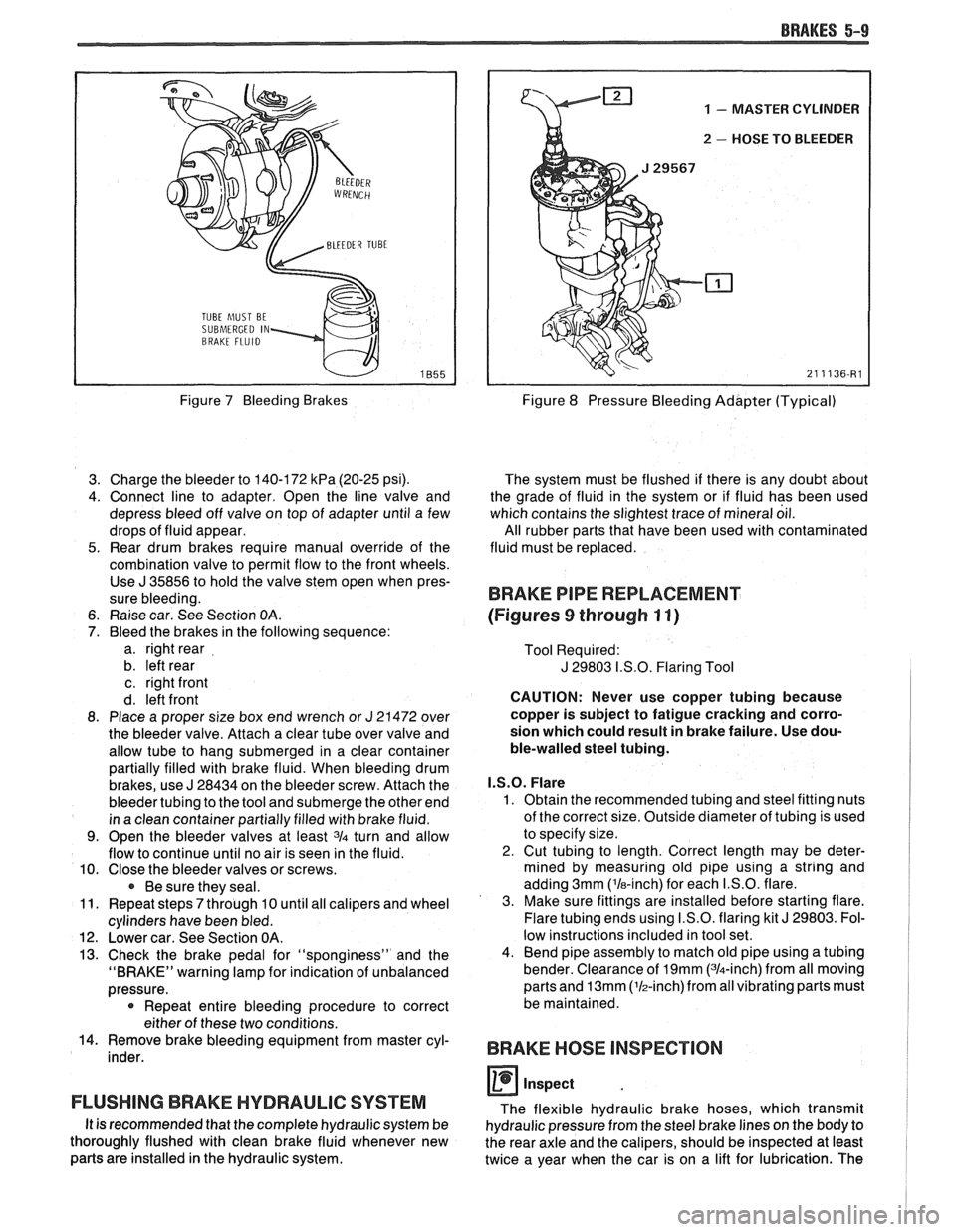
the bleeder valve. Attach a clear tube over valve and
allow tube to hang submerged in a clear container
partially filled with brake fluid. When bleeding drum
brakes, use
J 28434 on the bleeder screw. Attach the
bleeder tubing to the tool and submerge the other end
in a clean container partially filled with brake fluid.
9. Open the bleeder valves at least 3/4 turn and allow
flow to continue until no air is seen in the fluid.
10. Close the bleeder valves or screws.
Be sure they seal.
11. Repeat steps
7 through 10 until all calipers and wheel
cylinders have been bled.
12. Lower car. See Section OA.
13. Check the brake pedal for "sponginess" and the
"BRAKE" warning lamp for indication of unbalanced
pressure.
* Repeat entire bleeding procedure to correct
either of these two conditions.
14. Remove brake bleeding equipment from master cyl-
inder.
FLUSHING BRAKE HYDRAULIC SYSTEM
It is recommended that the complete hydraulic system be
thoroughly flushed with clean brake fluid whenever new
parts are installed in the hydraulic system.
1 - MASTER CYLINDER
u 2 - HOSE TO BLEEDER
Figure 8 Pressure Bleeding Adapter (Typical)
The system must be flushed if there is any doubt about
the grade of fluid in the system or if fluid has been used
which contains the slightest trace of mineral oil.
All rubber parts that have been used with contaminated
fluid must be replaced.
BRAKE PIPE REPLACEMENT
(Figures
9 through 11)
Tool Required:
J 29803 I.S.O. Flaring Tool
CAUTION: Never use copper tubing because
copper is subject to fatigue cracking and corro-
sion which could result in brake failure. Use dou-
ble-walled steel tubing.
I.S.O. Flare
1. Obtain the recommended tubing and steel fitting nuts
of the correct size. Outside diameter of tubing is used
to specify size.
2. Cut tubing to length. Correct length may be deter-
mined by measuring old pipe using a string and
adding 3mm ('la-inch) for each I.S.O. flare.
3. Make sure fittings are installed before starting flare.
Flare tubing ends using I.S.O. flaring kit
J 29803. Fol-
low instructions included in tool set.
4. Bend pipe assembly to match old pipe using a tubing
bender. Clearance of
19mm (314-inch) from all moving
parts and
13mm (lh-inch)from all vibrating parts must
be maintained.
BRAKE HOSE INSPECTION
0 inspect
The flexible hydraulic brake hoses, which transmit
hydraulic pressure from the steel brake lines on the body to
the rear axle and the calipers, should be inspected at least
twice a year when the car is on a lift for lubrication. The
Page 310 of 1825
BRAKES 5-17
maintaining proper wheel balance, brake drums should be
checked for balance. Brake drums may be checked for
balance on most off-the-car balancers.
COMBINATION VALVE
Testing Combination Valve Electrical Circuit
When removing the electrical wire connector from the
pressure differential switch, squeeze the
eliptical shaped
plastic locking ring and pull up. This will move the locking
tangs away from the switch. Pliers can be used to help
remove the connector.
1. Disconnect wire from switch terminal and use a
jumper to connect wire to a good ground.
2. Turn ignition key to "ON." The warning lamp should
light. If lamp does not light, bulb is burned out or
electrical circuit is faulty. Replace bulb or repair elec-
trical circuit as necessary.
3. When warning lamp lights, turn off ignition switch.
Disconnect jumper and connect wire to switch termi-
nal.
Testing Combination Valve Warning Lamp Switch
1. Attach a bleeder hose to a rear brake bleed screw and
immerse the other end of the hose in a container
partially filled with clean brake fluid. Be sure master
cylinder reservoirs are full.
2. Turn ignition switch to "ON." Open bleeder screw
while an assistant applies moderate pressure to the
brake pedal. Warning lamp should light. Close
bleeder screw before assistant releases brake pedal.
Apply brake pedal with moderate-to-heavy pressure.
Lamp should go out.
3. Attach the bleeder hose to a front brake bleeder
screw and repeat steps
1 and 2. Warning lamp action
should be the same as in step
2. Turn off ignition
switch.
4. If warning lamp does not light during steps 2 and 3,
but does light when a jumper is connected to ground,
the warning lamp switch portion of the combination
valve is faulty. Do not disassemble the combination
valve.
If any portion of the combination valve is faulty,
it must be replaced with a new combination valve.
Combination Valve Replacement
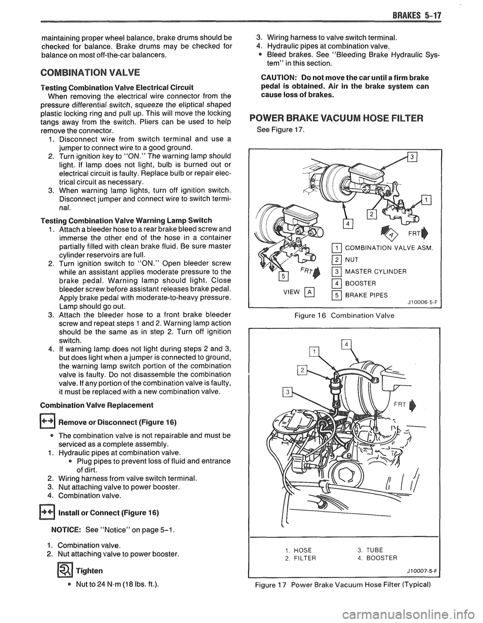
Remove or Disconnect (Figure
16)
r The combination valve is not repairable and must be
serviced as a complete assembly.
1. Hydraulic pipes at combination valve.
Plug pipes to prevent loss of fluid and entrance
of dirt.
2. Wiring harness from valve switch terminal.
3. Nut attaching valve to power booster.
4. Combination valve.
@ Install or Connect (Figure 16)
NOTICE: See "Notice" on page 5-1.
1. Combination valve.
2. Nut attaching valve to power booster.
Tighten
* Nut to 24 N.m (18 Ibs. ft.).
3. Wiring harness to valve switch terminal.
4. Hydraulic pipes at combination valve. * Bleed brakes. See "Bleeding Brake Hydraulic Sys-
tem" in this section.
CAUTION: Do not move the car until a firm brake
pedal is obtained. Air in the brake system can
cause loss of brakes.
POWER BRAKE VACUUM HOSE FILTER
See Figure 17.
COMBINATION VALVE ASM.
MASTER CYLINDER BRAKE PIPES
Figure 16 Combination Valve
2 FILTER 4. BOOSTER
Figure 17 Power Brake Vacuum Hose Filter (Typical)