1988 PONTIAC FIERO service reset
[x] Cancel search: service resetPage 135 of 1825

3-10 STEERING, SUSPENSION, TIRES AND WHEELS DIAGNOSIS
Reminder Keeps Operating With Key In Lock
Cylinder, Driver's Door Open Or Closed; Ceases
When Key Is Removed
Inspect
s Door jamb switch on driver's side misadjusted or
inoperative.
e Wire from signal switch to door jamb switch
shorted.
A. This condition indicates the lock cylinder or
the reminder switch is at fault. To verify,
check for continuity at the
"E" and "F"
male column connector contacts, with the
key removed from the lock cylinder. If
continuity exists, the fault is in the column.
B. Insert the key into the lock, then turn the
lock toward the "Start" position. If the
reminder stops when the key is in the
"Run" position or when it is turned past
"Run" toward "Start," the problem is a
sticky lock cylinder actuator.
COLUMN-MOUNTED DIMMER SWITCH
No "Low" or "High" Beam
Inspect
e Loose connector at dimmer switch
e Improper adjustment
e Internally damaged or worn switch. Check the
continuity on the switch at the It. green and at the
tan switch terminals by pushing in the plunger all
the way.
A click should be heard. If there is no
continuity, replace the dimmer switch. If there is
continuity, refer
to'section 8A for electricaldiag-
nosis.
PIVOT AND SWITCH ASSEMBLY
Switch Inoperative: No "Low," "High" and/or
"Wash"
e Loose body-to-switch connector
a Broken or damaged switch
Internally damaged or worn switch. Connect a
new switch without removing the old one. If the
system functions, replace the switch. If the
system doesn't function, refer to Section
8A for
electrical diagnosis.
STEERING GEAR AND PUMP LEAKS
General Procedure
Inspect
s Overfilled reservoir
s Fluid aeration and overflow
e , Hose connections
Verify exact point of leakage Example:
Torsion bar, stub shaft and
adjuster seals are close together; the exact
spot where the system is leaking may not be
clear.
Example: The point from which the fluid is
dripping is not necessarily the point where
the system is leaking; fluid overflowing from
the reservoir, for instance.
e When service is required:
A. Clean leakage area upon disassembly.
B. Replace leaking seal.
C. Check component sealing surfaces for
damage.
D. Reset bolt torque to specifications, where
required.
Some complaints about the power steering system
may be reported as:
A. Fluid leakage on garage floor
B. Fluid leaks visible on steering gear or pump
C. Growling noise, especially when parking or
when engine is cold
D. Loss of power steering when parking
E. Heavy steering effort
When troubleshooting these kinds of complaints,
check for an external leak in the power steering system.
For further diagnosis of leaks, refer to External
Leakage Check in this section.
External Leakage Check
Fig. 12
The purpose of this procedure is to pinpoint the
location of the leak.
In some cases, the leak can easily be located. But,
seepage-type leaks may be more difficult to isolate. To
locate seepage leaks, use the following method.
1. With the engine off, wipe dry the complete power
steering system.
2. Check the fluid level in the pump's reservoir. Add
fluid if necessary.
3. Start the engine, then turn the steering wheel
from stop to stop several times. Do not hold it at
a stop for any length of time, as this can damage
the power steering pump. It is easier if someone
else operates the steering wheel while you search
for the seepage.
4. Find the exact area of the leak and repair leak.
SEAL REPLACEMENT
RECOMMENDATIONS
Lip seals, which seal rotating shafts, require
special treatment. This type of seal is used on the
steering gear and on the drive shaft of the pump. When
there is a leak in one of these areas, always replace the
seal(s), after inspecting and thoroughly cleaning the
sealing surfaces. Replace the shaft only if very severe
pitting is found. If the corrosion in the lip seal contact
zone is slight, clean the surface of the shaft with crocus
cloth. Replace the shaft only if the leakage cannot be
stopped by first smoothing with crocus cloth.
Page 268 of 1825
REAR AXLE 481-1 5
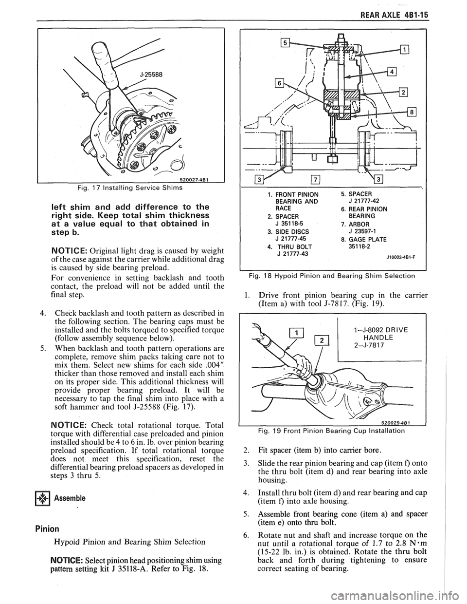
Fig. 17 Installing Service Shims
left shim and add difference to the
right side. Keep total shim thickness
at a value equal to that obtained in
step b.
NOTICE: Original light drag is caused by weight
of the case against the carrier while additional drag
is caused by side bearing preload.
For convenience in setting backlash and tooth
contact, the preload will not be added until the
final step.
4. Check backlash and tooth pattern as described in
the following section. The bearing caps must be
installed and the bolts torqued to specified torque
(follow assembly sequence below).
5. When backlash and tooth pattern operations are
complete, remove shim packs taking care not to
mix them. Select new shims for each side
.004"
thicker than those removed and install each shim
on its proper side. This additional thickness will
provide proper bearing preload. It will be
necessary to tap the
final shim into place with a
soft hammer and tool
5-25588 (Fig. 17).
1. FRONT PINION
BEARING AND
RACE
2. SPACER
J 351 18-5
3.
SIDE DISCS J 21 777-45
4. THRU BOLT J 21 777-43 5.
SPACER
J 21777-42
6. REAR PINION
BEARING
7. ARBOR
J 23597-1
8. GAGE PLATE
351 18-2
J10003-4B1 -F
Fig. 18 Hypoid Pinion and Bearing Shim Selection
1. Drive front pinion bearing cup in the carrier
(Item a) with tool
5-7817. (Fig. 19).
1-J-8092 DRIVE
NOTICE: Check total rotational torque. Total
torque with differential case preloaded and pinion Fig. 19 Front Pinion Bearing Cup Installation
installed should be 4 to 6 in. lb, over pinion bearing
preload specification. If total rotational torque 2. Fit spacer (item
b) into carrier bore.
does
not- meet this specification, reset the
differential bearing preload spacers as developed in 3. Slide the rear pinion bearing and cap (item f) onto
steps
3 thru 5. the
thru bolt (item d) and rear bearing into axle
housing.
Assemble 4. Install thru bolt (item d) and rear bearing and cap
(item
f) into axle housing.
5. Assemble front bearing cone (item a) and spacer
(item e) onto thru bolt.
Pinion 6. Rotate nut and shaft and increase torque on the Hypoid Pinion and Bearing Shim Selection
nut until a rotational toraue of 1.7 to 2.8 N-m
(15-22 lb. in.) is obtained: Rotate the thru bolt
NOTICE: Select pinion head positioning shim using back
and forth during tightening to ensure
pattern setting kit
J 35118-A. Refer to Fig. 18. correct
seating of bearing.
Page 582 of 1825
DRIVEABILITY AND EMISSIONS - 5.BL (VIN E) 6E2-CZ-7
Refer to the disassembled view (Figure C2-8) for
identification of parts during repair procedures.
Service repair of individual components is performed
without removing the TBI unit from the engine. If
removed, it is essential that care is taken to prevent
damage to the throttle valve or sealing surface while
performing any service.
Whenever service is performed on the TBI or any
of its components, first remove the air cleaner, adapter
and air cleaner gaskets. Discard the gaskets and
replace them with new ones before replacing the air
cleaner after service is complete.
When disconnecting the fuel lines, be sure to use a
backup wrench
(J-29698-A, or BT8251-A, or
equivalent) to keep the TBI nuts from turning.
Fuel Pressure Relief
The TBI Model 220 on this engine contains a
constant bleed feature in the pressure regulator that
relieves pressure. Therefore, no special pressure relief
procedure is required.
Fuel System Pressure Pest
A fuel system pressure test is part of several of the
diagnostic charts and symptom checks. To perform
this test, follow this procedure:
1. Turn engine "OFF" to relieve fuel pressure.
2. Remove air cleaner and plug THERMAC vacuum
port on TBI.
3. Uncouple fuel supply flexible hose in engine
compartment. Install fuel pressure gage
J-29658AlBT8205 and adapter 29658A-85
between steel line and flexible hose.
4. Tighten gage in line to ensure no leaks occur
during testing.
5. Start car and observe fuel pressure reading. It
should be 62-90
kPa (9-13 psi); if not, refer to
CHART A-7.
6. Relieve fuel pressure.
7. Remove fuel pressure gage.
8. Reinstall fuel line.
9. Start car and check for fuel leaks.
10. Remove plug from vacuum port and install air
cleaner with new gasket.
Cleaning and inspection
All TBI component parts, with the exception of
those noted below, should be cleaned in a cold
immersion cleaner such as Carbon
X (X-55) or
equivalent.
NOTICE: The throttle position sensor ('I'PS), idle air
control
(IAC) valve, pressure regulator
diaphragm assembly, fuel injectors or other
components containing
rubber,should NOT be placed in a solvent
or cleaner bath. A chemical reaction will
cause these parts to swell, harden or
distort. Do not soak the throttle body with
the above parts attached. If the throttle
body assembly requires cleaning, soaking
time in the cleaner should be kept to a
minimum. Some models have hidden
throttle shaft dust seals that could lose
their effectiveness by extended soaking.
1. Clean all metal parts thoroughly and blow dry
with shop air. Be sure that all fuel and air
passages are free of dirt or burrs.
2. Inspect mating casting surfaces for damage that
could affect gasket sealing.
Thread Locking Compound
Service repair kits are supplied with a small vial
of thread locking compound with directions for use. If
material is not available, use Loctite 262, or
GM part
number 10522624, or equivalent.
NOTICE: Do not use a higher strength locking
compound than recommended, since to do
so could make removing the screw
extremely difficult, or result in damaging
the screw head.
FUEL METER COVER ASSEMBLY
Replacement (Figure
C2-9)
The fuel meter cover assembly contains the fuel
pressure regulator assembly. The regulator has been
adjusted at the factory and should only be serviced as
a complete preset assembly.
CAUTION: DO NOT remove the four screws
securing the pressure regulator to
the fuel meter cover. The fuel
pressure regulator includes a large
spring under heavy compression
which, if accidentally released,
could cause personal injury.
Disassembly might also result in a
fuel leak between the diaphragm
and the regulator container.
Remove or Disconnect
I. Electrical connectors to fuel injectors. (Squeeze
plastic tabs and pull straight up.)
2. Long
and short fuel meter cover screw assemblies.
3. Fuel meter cover assembly.
Page 586 of 1825
DRIVEABILITY AND EMISSIONS - 5.0L (VIN E) 6EZ-CZ-11
IDLE AIR CONTROL (IAC) VALVE
IAC VALVE GASKET
THROTTLE BODY ASSEMBLY
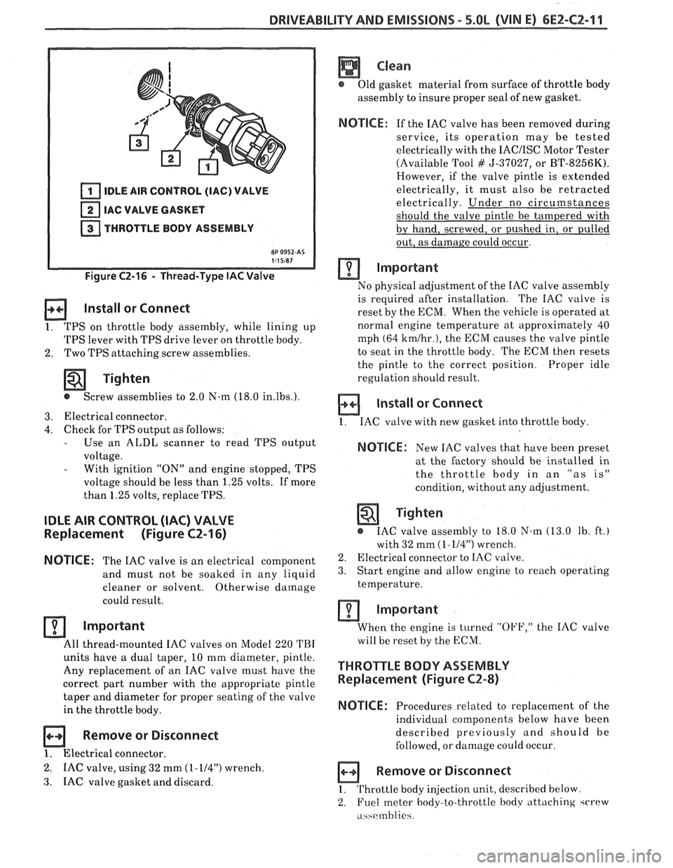
Figure C2-16 - Thread-Type IAC Valve
Install or Connect
1. TPS on throttle body assembly, while lining up
TPS lever with TPS drive lever on throttle body.
2. Two
TPS attaching screw assemblies.
Tighten
@ Screw assemblies to 2.0 N-m (18.0 in.lbs.).
3. Electrical connector.
4. Check for TPS output as follows: - Use an ALDL scanner to read TPS output
voltage.
- With ignition "ON" and engine stopped, TPS
voltage should be less than 1.25 volts. If more
than 1.25 volts, replace TPS.
IDLE AIR CONTROL (IAC) VALVE
Replacement (Figure CZ-16)
NOTICE:
The IAC valve is an electrical
component
and must not be soaked in any liquid
cleaner or solvent. Otherwise
damage
could result.
Important
All thread-mounted IAC valves on Model 220 TBI
units have a dual taper, 10 mm diameter, pintle.
Any replacement of an IAC valve must have the
correct part number with the appropriate pintle
taper and diameter for proper seating of the valve
in the throttle body.
Remove or Disconnect
1. Electrical connector.
2. IAC valve, using 32 mm (1-114") wrench.
3. IAC
valve gasket and discard.
Clean
@ Old gasket material from surface of throttle body
assembly to insure proper seal of new gasket.
NOTICE: If the IAC valve has been removed during
service, its operation may be tested
electrically with the
IACIISC Motor Tester
(Available Tool
# 5-37027, or BT-8256K).
However, if the valve pintle is extended
electrically, it must also be retracted
electrically. Under no circumstances
should the valve pintle be tampered with
by hand, screwed, or pushed in, or pulled
out, as damage could occur.
Important
No physical adjustment of the IAC valve assembly
is required after installation. The IAC valve is
reset by the ECM. When the vehicle is operated at
normal engine temperature at approximately 40
mph (64
kmlhr.), the ECM causes the valve pintle
to seat in the throttle body. The ECM then resets
the pintle to the correct position. Proper idle
regulation should result.
Install or Connect
1. IAC valve with new gasket into throttle body
NOTICE: New IAC valves that have been preset
at the factory should be installed in
the throttle
body in an "as is"
condition, without any adjustment.
Tighten
@ IAC valve assembly to 18.0 N.m (13.0 lb. ft.)
with 32 mm
(1-114") wrench.
2. Electrical connector to IAC valve.
3. Start engine and allow engine to reach operating
temperature.
Important
When the engine is turned "OFF," the IAC valve
will be reset by the ECM.
THROTTLE BODY ASSEMBLY
Replacement (Figure CZ-8)
NOTICE:
Procedures related to replacement of the
individual components below have been
described previously and should be
followed, or damage could occur.
Remove or Disconnect
1. Throttle body injection unit, described below
2. Fuel
meter body-to-throttle hodv attaching ~CI'PW
.i~~rmhlie
Page 891 of 1825
6E3-CZ-4 5.OL (VIN F) & 5.7L(VIN 8) DRIVEABILITY AND EMISSIONS
FUEL INJECTOR
1 INTAKE MANIFOLD
( INTAKE VALVE
1 ELECTRICAL TERMINAL
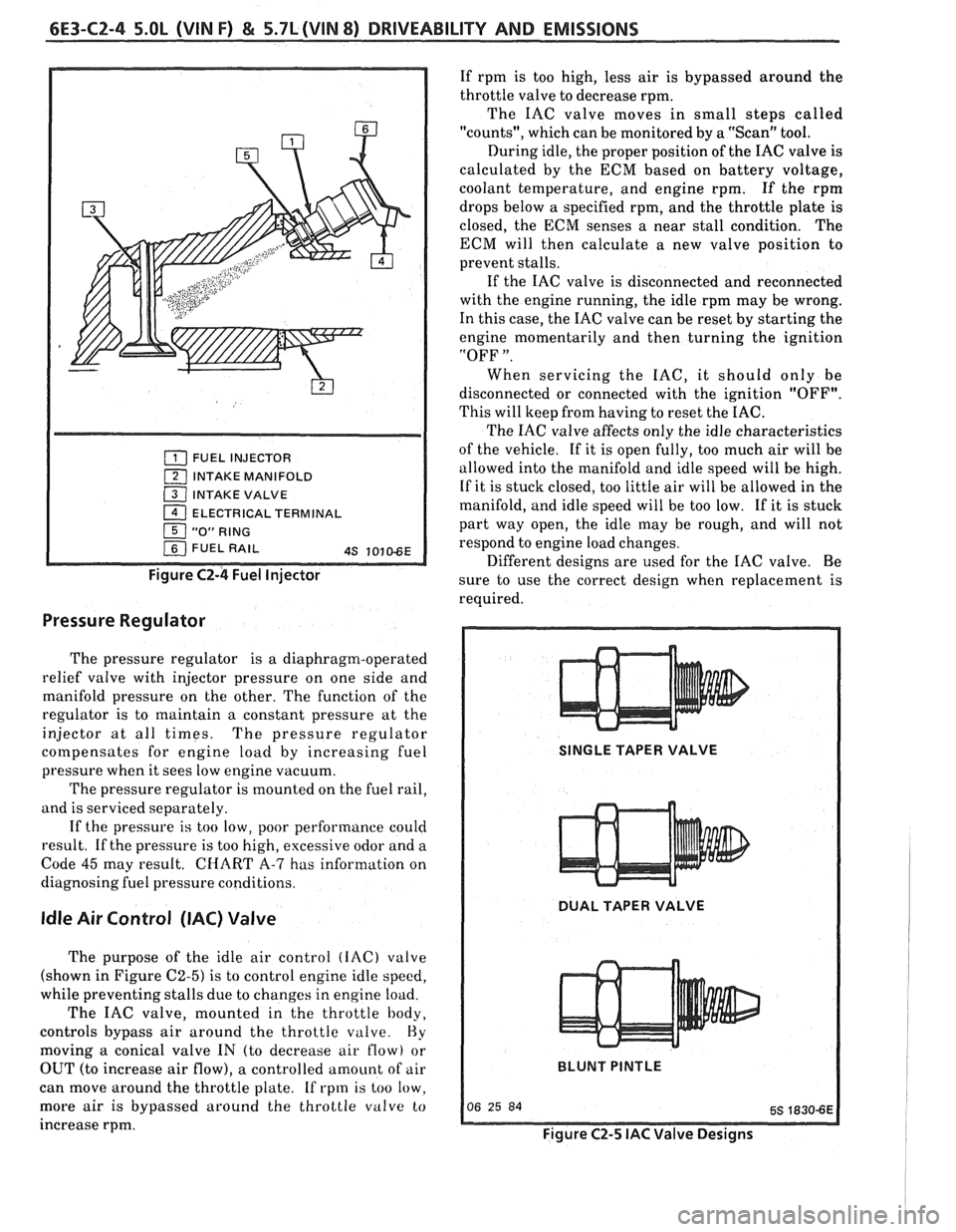
Figure C2-4 Fuel Injector
Pressure Regulator
The pressure regulator is a diaphragm-operated
relief valve with injector pressure on one side and
manifold pressure on the other. The function of the
regulator is to maintain a constant pressure at the
injector at all times. The pressure regulator
cotnpensates for engine load by increasing fuel
pressure when it sees low engine vacuum.
The pressure regulator is mounted on the fuel rail,
and is serviced separately.
If the pressure
is too low, poor performance could
result. If the pressure is too high, excessive odor and a
Code
45 may result. CHART A-7 has information on
diagnosing fuel pressure conditions.
Idle Air Control (IAC) Valve
The purpose of the idle air control (IAC) valve
(shown in Figure
C2-5) is to control engine idle speed,
while preventing stalls due to changes in engine load.
The IAC valve, mounted in the throttle body,
controls bypass air around the throttle
valve. Hy
moving a conical valve IN (to decrease air flow) or
OUT (to increase air flow), a controlled amount of air
can move around the throttle plate. If rpm is too low.
more air
is bypassed around the throttle valve to
increase rpm. If
rpm is too high, less air is bypassed around the
throttle valve to decrease rpm.
The IAC valve moves in small steps called
"counts", which can be monitored by a "Scan" tool.
During idle, the proper position of the IAC valve is
calculated by the ECM based on battery voltage,
coolant temperature, and engine rpm. If the rpm
drops below
a specified rpm, and the throttle plate is
closed, the ECM senses a near stall condition. The
ECM will then calculate a new valve position to
prevent stalls.
If the IAC valve is disconnected and reconnected
with the engine running, the idle rpm may be wrong.
In this case, the IAC valve can be reset by starting the
engine momentarily and then turning the ignition
"OFF
".
When servicing the IAC, it should only be
disconnected or connected with the ignition "OFF".
This will keep from having to reset the IAC.
The IAC valve affects only the idle characteristics
of the vehicle. If it is open fully, too much air will be
allowed into the manifold and idle speed will be high.
If it is stuck closed, too little air will be allowed in the
manifold, and idle speed will be too low. If it is stuck
part way open, the idle may be rough, and will not
respond to engine load changes.
Different designs are used for the IAC valve. Be
sure to use the correct design when replacement is
required.
SINGLE TAPER VALVE
DUAL TAPER VALVE
BLUNT
PINTLE
Figure C2-5 IAC Valve Designs
Page 965 of 1825
6E-4 DRIVEABILITY AND EMISSIONS - FUEL INJECnON
and ohms. You should understand what happens in a
circuit with an open or a shorted wire. You should be
able to read and understand a wiring diagram. A
short to ground
is referred to as a ground to
distinguish it from a short between wires.
Use of Circuit Testing Tools
You should know how to use a test light, how to
connect and use
a tachometer, and how to use jumper
wires to by-pass components to test circuits. Care
should be taken to not deform the terminal when
testing.
Use of Digital Volt-Ohm Meter (DVM)
You should be familiar with the digital volt-ohm
Meter, particularly essential tool J-29125-A,
J34029A
or equivalent. You should be able to measure voltage,
resistance, and current, and know how to use the
meter correctly.
The digital volt-ohm meter is covered in the
"Special
ToolsJ'portion of this section.
DIAGNOSTIC INFORMATION
The electronic control module (ECM) is equipped
with a self-diagnosis system which detects system
failure and aids the technician by identifying the
circuit at fault via a trouble code. Below is
information about the way the ECM displays a
problem and how this corresponds to a trouble code in
the ECM. The ECM can also indicate an "Open Loop"
or "Closed Loop" mode.
"'Service Engine Soonw Light
This light is on the instrument panel, and has two
functions:
@ It is used to tell the driver that a problem has
occurred, and that the vehicle should be taken for
service as soon as reasonably possible.
@ It is used by the technician to read out "Trouble
CodesJ' to help diagnose system problems.
As a bulb and system check, the light will come
"ON" with the key "ON" and the engine not running.
When the engine is started, the light will turn "OFF".
If the light remains "ONJ', the self-diagnostic system
has detected a problem. If the problem goes away, the
light will go out in most cases after 10 seconds, but a
Trouble Code will remain stored in the ECM.
Intermittent "Service Engine Soon" Light
The diagnostic charts in Section "A" are set up to
check whether or not a stored trouble code is
"intermittent" or "hard". An
"intermittent" code is one which does not
always reset when the code setting parameters are
met, or is not present while you are working on the
vehicle. This is often caused by
a loose connection.
The facing page will contain diagnostic aids to help in
detecting
intermittents.
A "hard" code is one which is present when you
are working on the vehicle and the condition still
exists while working on the vehicle. The chart with
the stored trouble code number will lead you to the
cause of the problem.
Trouble Codes
The engine control module (ECM) is really a
computer. It uses sensors to look at many engine
operating conditions. It has
a memory and it knows
what certain sensor readings should be under certain
conditions. These conditions are described on the
facing page of each Trouble Code chart. If a sensor
reading is not what the ECM thinks it should be, the
ECM will turn "ON" the "Service Engine Soon" light
on the instrument panel, and will store a Trouble Code
in the memory. The Trouble Code tells which circuit
the trouble is in. A circuit consists of a sensor (such as
coolant temperature), the wiring and connectors to it,
and the ECM.
i
To get a Trouble Code out of the ECM, we use the
assembly line diagnostic link (ALDL) connector.
!
ALDL Connector I
I
The assembly line diagnostic link (ALDL) is a
diagnostic connector located in the passenger
compartment (Figure 2). It has terminals which are
used in the assembly plant to check that the engine is
operating properly before it leaves the plant.
Terminal "B" is the Diagnostic terminal, and it can be
connected to terminal
"A", or ground, to enter the
Diagnostic mode, or the Field Service Mode.
The ALDL connector is also used by "ScanJ' tools to
read information from the ECM via the Serial Data
Line. Serial Data information
is used extensively
throughout the manual.
Diagnostic Mode
1
If the Diagnostic terminal is grounded with the
ignition "ON" and the engine stopped, the system will
enter the Diagnostic Mode. In this mode the ECM
will:
1. Display a Code 12 by flashing the "Service Engine
Soon" light (indicating the system is operating). A
Code 12 consists of one flash, followed by a short
pause, then two flashes in quick succession. This
code will be flashed three times. If no other codes
Page 1551 of 1825
RADIO
(Continued from previous page)
1. Remove the Cancel Cam. Inspect the Slip
Rings on the Cancel Cam and the spring
loaded contacts on the Turn Signal
Switch. Replace as necessary. Incorrect
or missinglubricant on the Cam can cause
premature failure. Take care to keep lubri-
cant or any foreign material away from
the
LED'S and receptors as it will hinder
or prevent proper operation. The correct
lubricant is part no.
26002312.
F: OPTICAL SLlPRlNG TEST (TABLE 2)
Measure: VOLTAGE
At: TOOL J-35630 (Connected)
Conditions:
@ Engine running
0 Press the Preset, Mute and RCL buttons
or the Seek, Scan, and
AMIFM buttons
on the Remote Control Head
sirnultaneoulsy
0 Turn the steering wheel slowly while
measuring
Measure
Correct I For Diagnosis I
I I Between 3.0 1 I Terminal C & and 4.5 volts
1 Ground 1 at all wheel
I 1 positions I I
I . If the voltage is correct, go to Table 3. (
1. Replace the Remote Control Head. Refer
to Section
3B5 for replacement pro-
cedures.
F: OPTICAL SLlPRllUG TEST (TABLE 3) H: NOlSE DIAGNOSIS
Remove the Cancel Cam. Refer to Section Unplug
the Antenna at the back of the Radio.
3B5 for removal procedures.
If noise disappears, it was being picked up
0 Make the following measurements.
by the Antenna. Consult the Delco Sound
Service Guide for Antenna noise diagnosis.
If the noise persists, it is coming in the Radio
wiring. Refer to the following chart for a
possible cause and corrective action.
At: CONNECTOR 6210 (Connected)
@ Ignition Switch: RUN
Shield the Turn Signal Switch Light
Receptors from outside light with a dark
1. Replace the Turn Signal Switch. Refer to
6: ANTENNA TEST
Check connectors Radio and Antenna ends of
Antenna Coaxial Cable. Connect a known good
test Antenna to the Radio. The test Antenna
must be designed for use
with ARC Radios, as
ARC Radios use a different size Antenna con-
nector than conventional Radios.
@ If Radio plays, replace the Antenna.
If Radio still does not operate, send Radio to
an authorized AC-Delco repair station.
Refer to section 9A for removal and replace-
ment procedures.
Page 1615 of 1825
8C.4 INSTRUMENT PANEL, GAGES & CONSOLE
ON-CAR SERVlCE
lNSTRUMEMT PANEL PAD
Figure 601
Remove or Disconnect
1. Four (4) screws in defroster ducts.
2. Screws
under lip of
I.P, pad.
3. I.P. pad from carrier.
lnstall or Connect
1. I.P. to carrier.
2. Screws
under lip of I.P. pad.
3. Four (4) screws in defroster ducts.
INSTRUMENT PANEL CLUSTER
Figure 683
Remove or Disconnect
1. Right and left lower trim plates. Removal of
lower I.P. covers not required.
2. Instrument cluster trim plate.
3. Six (6) cluster attachment screws, pull cluster
back and disconnect speedo cable and electrical
connections.
4. Trip odometer, reset knob (if so equipped) and
remove cluster lens.
5. Individual gages and/or speedo head are now
accessible for service or replacement. If service is
intended for only gages or tachometer, skip Step
3.
Install or Connect
1. Trip odometer, reset knob (if so equipped) and
remove cluster lens.
2. Six
(6) cluster attachment screws, pull cluster
back and disconnect speedo cable and electrical
connections.
3. Instrument cluster trim plate.
4. Right and left lower trim plates. Removal of
lower I.P. covers not required.
INSTRUMENT PANEL CARRIER
Figure 602
Remove or Disconnect
Negative battery cable.
Console. Instrument panel pad and lower hush panels.
Right and left lower I.P. covers and trim plates.
Instrument panel cluster and headlight switch.
Lower steering column.
Five (5) upper and six (6) lower I.P. carrier to
cowl screws.
Instrument panel electrical harness at cowl
(bulkhead) connector, and under dash.
I.P. carrier from car.
10. I.P. mounted components (A/C, defroster ducts,
wiring harness, etc.) are now accessible for service
or replacement.
11. Any seals or sealant damaged during
disassembly.
Install or Connect
I.P. carrier to car.
Instrument panel electrical harness at cowl
(bulkhead) connector, and under dash.
Five (5) upper and six (6) lower I.P. carrier to
cowl screws.
Steering column.
Instrument panel cluster and headlight switch.
Right and left lower I.P. covers and trim plates.
Instrument panel pad and lower hush panels.
Console.
Negative battery cable.
HEADLIGHT SWITCH
Figure 620
Remove or Disconnect
1. Right and left lower trim plates. Removal of
lower I.P.
cover(s) not required.
2. I.P. cluster trim plate.
3. Two (2) switch assembly retaining screws.
4. Depress side tangs and pull switch assembly from
I.P.
5. Individual switches of assembly are now
accessible for service or replacement.
Install or Connect
1. Depress side tangs and replace switch assembly
to I.P.
2. Two
(2) switch assembly retaining screws.
3. I.P. cluster trim plate.
4. Right and
left lower trim plates. Removal of
lower I.P.
cover(s) not required.
DASH MOUNTED ACCESSORY SWITCHES
Figure 62 1
Installation for various dash mounted accessory
switches is shown in Fig.
62 1.
CONSOLE MOUNTED SWITCHES AND
ACCESSORIES
Figure 6 17
Installation of various console mounted switches,
lights and accessories is shown in Figure 617.
CONSOLE
Remove or Disconnect
1. Negative battery cable.
2. Shift gate trim plate. Requires removal
of shift
handle and seven (7) screws.
3. Radio/A/C-heater controller trim plate.