1988 PONTIAC FIERO headlight bulb
[x] Cancel search: headlight bulbPage 115 of 1825
26-8 CHASSIS SWEET METAL
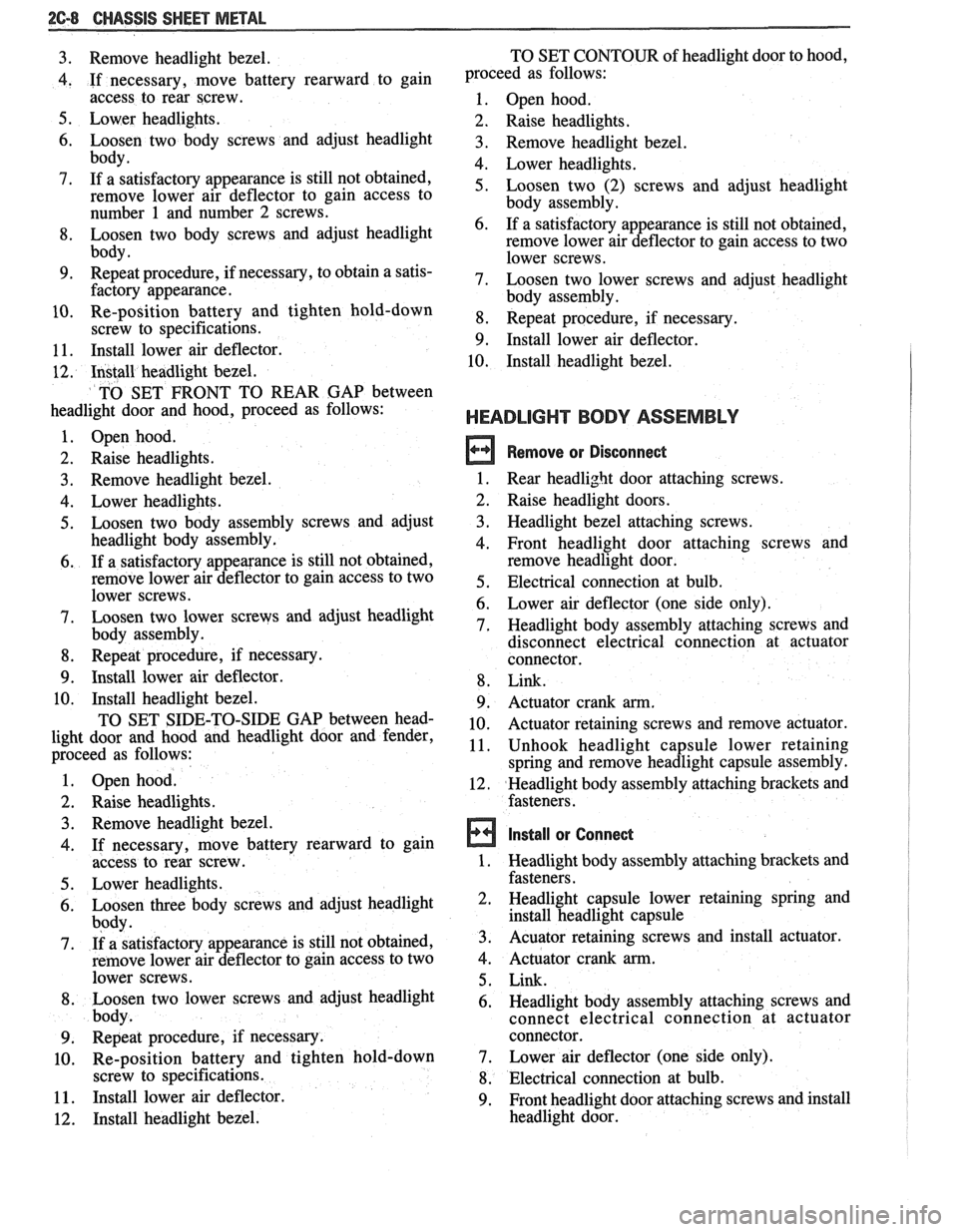
3. Remove headlight bezel.
4. If necessary, move battery rearward to gain
access to rear screw.
5. Lower headlights.
6. Loosen two body screws and adjust headlight
body.
7. If a satisfactory appearance is still not obtained,
remove lower air deflector to gain access to
number 1 and number 2 screws.
8. Loosen two body screws and adjust headlight
body.
9. Repeat procedure, if necessary, to obtain a satis-
factory appearance.
10. Re-position battery and tighten hold-down
screw to specifications.
11. Install lower air deflector.
12. Install headlight bezel.
TO SET FRONT TO REAR
GAP between
headlight door and hood, proceed as follows:
1. Open hood.
2. Raise headlights.
3. Remove headlight bezel.
4. Lower headlights.
5. Loosen two body assembly screws and adjust
headlight body assembly.
6. If a satisfactory appearance is still not obtained,
remove lower air deflector to gain access to two
lower screws.
7. Loosen two lower screws and adjust headlight
body assembly.
8. Repeat procedure, if necessary.
9. Install lower air deflector.
10. Install headlight bezel.
TO SET SIDE-TO-SIDE GAP between head-
light door and hood and headlight door and fender,
proceed as follows:
Open hood.
Raise headlights. Remove headlight bezel.
If necessary, move battery rearward to gain
access to rear screw.
Lower headlights.
Loosen three body screws and adjust headlight
body.
If a satisfactory appearance is still not obtained,
remove lower air deflector to gain access to two
lower screws.
Loosen two lower screws and adjust headlight
body.
Repeat procedure, if necessary.
Re-position battery and tighten hold-down
screw to specifications.
Install lower air deflector.
Install headlight bezel. TO
SET CONTOUR of headlight door to hood,
proceed as follows:
1. Open hood.
2. Raise headlights.
3. Remove headlight bezel.
4. Lower headlights.
5. Loosen two (2) screws and adjust headlight
body assembly.
6. If a satisfactory appearance is still not obtained,
remove lower air deflector to gain access to two
lower screws.
7. Loosen two lower screws and adjust headlight
body assembly.
8. Repeat procedure, if necessary.
9. Install lower air deflector.
10. Install headlight bezel.
HEADLIGHT BODY ASSEMBLY
Remove or Disconnect
1. Rear headlight door attaching screws.
2. Raise headlight doors.
3. Headlight bezel attaching screws.
4. Front headlight door attaching screws and
remove headlight door.
5. Electrical connection at bulb.
6. Lower air deflector (one side only).
7. Headlight body assembly attaching screws and
disconnect electrical connection at actuator
connector.
8. Link.
9. Actuator crank arm.
10. Actuator retaining screws and remove actuator.
11. Unhook headlight capsule lower retaining
spring and remove headlight capsule assembly.
12. Headlight body assembly attaching brackets and
fasteners.
Install or Connect
1. Headlight body assembly attaching brackets and
fasteners.
2. Headlight capsule lower retaining spring and
install headlight capsule
3. Acuator retaining screws and install actuator.
4. Actuator crank arm.
5. Link.
6. Headlight body assembly attaching screws and
connect electrical connection at actuator
connector.
7. Lower air deflector (one side only).
8. Electrical connection at bulb.
9. Front headlight door attaching screws and install
headlight door.
Page 1474 of 1825
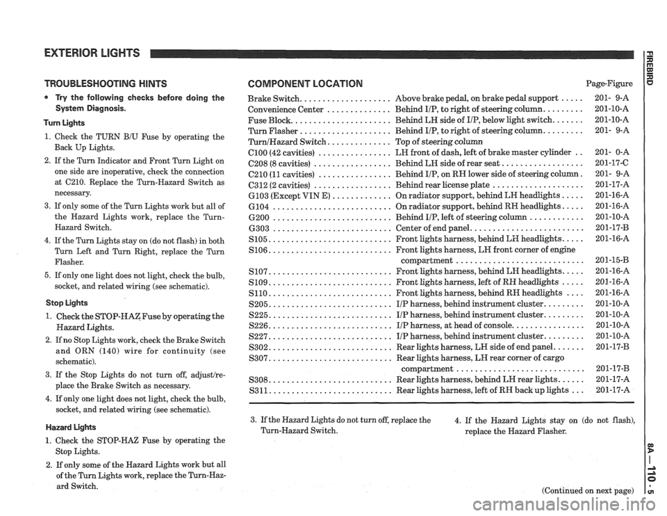
TROUBLESHOOTING HINTS
Try the following checks before doing the
System Diagnosis.
Turn Lights
1. Check the TURN B/U Fuse by operating the
Back Up Lights.
2. If the Turn Indicator and Front Turn Light on
one side are inoperative, check the connection
at
C210. Replace the Turn-Hazard Switch as
necessary.
3. If only some of the Turn Lights work but all of
the Hazard Lights work, replace the
Turn-
Hazard Switch.
4. If the Turn Lights stay on (do not flash) in both
Turn Left and Turn Right, replace the Turn
Flasher.
5. If only one light does not light, check the bulb,
socket, and related wiring (see schematic).
Stop Lights
1. Check the STOP-HAZFuse by operating the
Hazard Lights.
2. If no Stop Lights work, check the Brake Switch
and ORN (140) wire for continuity (see
schematic).
3. If the Stop Lights do not turn off, adjustlre-
place the Brake Switch as necessary.
4. If only one light does not light, check the bulb,
socket, and related wiring (see schematic).
Hazard Lights
1. Check the STOP-HAZ Fuse by operating the
Stop Lights.
2. If only some of the Hazard Lights work but all
of the Turn Lights work, replace the
Turn-Haz-
ard Switch.
COMPONENT LOCATION Page-Figure
................... ..... Brake Switch. Above
brake pedal, on brake pedal support 201- 9-A
.............. ........ Convenience
Center Behind IIP, to right of steering column. 201-10-A
Fuse Block.
..................... Behind LH side of IIP, below light switch. ...... 201-10-A
Turn Flasher
.................... Behind IIP, to right of steering column. ........ 201- 9-A
............. TurnlHazard Switch. Top of steering column
C100 (42 cavities) ................ LH front of dash, left of brake master cylinder .. 201- 0-A
................. ................. C208 (8 cavities) Behind LH side of rear seat. 201-17-C
C210
(11 cavities) ................ Behind IIP, on RN lower side of steering column. 201- 9-A
................. .................... 6312 (2 cavities) Behind rear license plate 201-17-A
............. ..... 6103 (Except VIN E) On radiator support, behind LN headlights 201-16-A
.......................... .... 6104
On radiator support, behind RH headlights. 201-16-A
.......................... ............ 6200 Behind IIP, left of steering column 201-10-A
........................ .......................... 6303 Center of end panel. 201-17-B
.......................... .... S105. Front lights harness, behind LH headlights. 201-16-A
.......................... S106. Front lights harness, LN front corner of engine
compartment..
.......................... 201-1543
.......................... .... S107. Front lights harness, behind LH headlights. 201-16-A
.......................... ..... S109. Front lights harness, left of RH headlights 201-16-A
S110. .......................... Front lights harness, behind RH headlights .... 201-16-A
S205. .......................... IIP harness, behind instrument cluster. ........ 201-10-A
S225. .......................... IIP harness, behind instrument cluster. ........ 201-10-A
S226. .......................... IIP harness, at head of console. ............... 201-10-A
S227. .......................... IIP harness, behind instrument cluster. ........ 201-10-A
S302. .......................... Rear lights harness, LW side of end panel. ...... 201-17-B
.......................... S307. Rear lights harness, LH rear corner of cargo
compartment..
.......................... 201-17-B
.......................... ..... S308. Rear lights harness, behind LH rear lights. 201-17-A
S311. .......................... Rear lights harness, left of RH backup lights ... 201-17-A
3. If the Hazard Lights do not turn off, replace the
4. If the Hazard Lights stay on (do not flash),
Turn-Hazard Switch.
replace the Hazard Flasher.
(Continued on next page)
Page 1477 of 1825
EXTERIOR LIGHTS I$
(Continued from previous page)
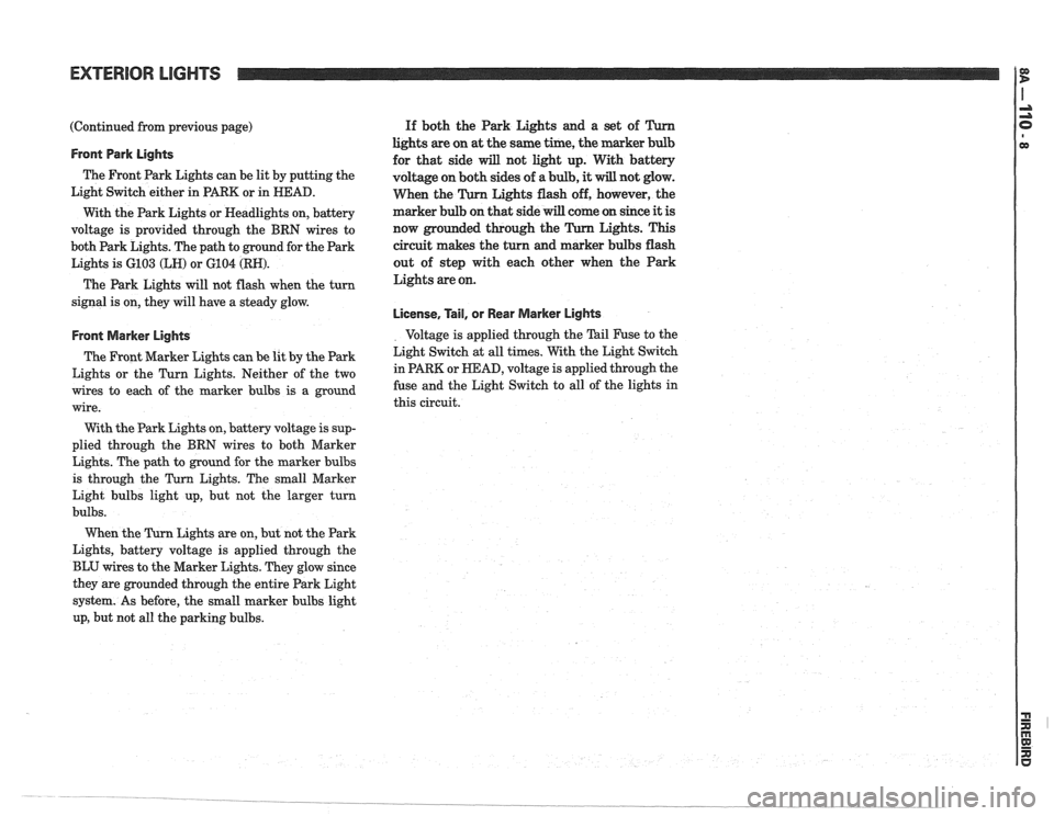
Front Park Lights
The Front Park Lights can be lit by putting the
Light Switch either in
PARK or in HEAD.
With the Park Lights or Headlights on, battery
voltage is provided through the BRN wires to
both Park Lights. The path to ground for the Park
Lights is
6103 (LH) or 6104 (RN).
The Park Lights will not flash when the turn
signal is on, they will have a steady glow.
Front Marker Lights
The Front Marker Lights can be lit by the Park
Lights or the Turn Lights. Neither of the two
wires to each of the marker bulbs is
a ground
wire.
With the Park Lights on, battery voltage is sup-
plied through the BRN wires to both Marker
Lights. The path
to ground for the marker bulbs
is through the
Turn Lights. The small Marker
Light bulbs light up, but not the larger turn
bulbs.
Lights are on, but not the Park
Lights, battery voltage is applied through the
BLU wires
to the Marker Lights. They glow since
they are grounded through the entire Park Light
system. As before, the small marker bulbs light
up, but not all the parking bulbs. If
both the Park Lights and a set of
lights are on at the same time, the marker
for that side
will not light up. With battery
voltage on both sides of
a bulb, it will not glow.
When the Lights flash off, however, the
marker bulb on that side will come on since
it is
now grounded through the Lights. This
circuit
makes the turn and marker bulbs flash
out of step with each other when the Park
Lights are on.
License, Tail, or Rear Marker Lights
Voltage is applied through the Tail Fuse to the
Light Switch at all times. With the Light Switch
in PARK or
HEAD, voltage is applied through the
fuse and the Light Switch to all of the lights in
this circuit.
Page 1483 of 1825
EXTERIOR LIGHTS WITH LAMP MONITOR I:
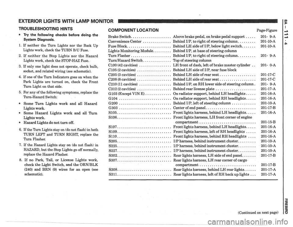
TROUBLESHOOTING HINTS
r Try the follovving checks before doing the
Systern Diagnosis .
1 . If neither the Turn Lights nor the Back Up
Lights work. check the TURN
BIU Fuse .
2 . If neither the Stop Lights nor the Hazard
Lights work. check the STOP-HAZ Fuse
.
3 . If only one light does not operate. check bulb.
socket. and related wiring (see schematic)
.
4 . If one of the Turn Indicators goes on when the
Park Lights are turned on. check the Front
Turn Light on that side
.
5 . For any of the following symptoms. replace the
Turn-Hazard Switch:
Some Turn Lights work and all Hazard
Lights work
.
@ Some Hazard Lights work and all Turn
Lights work
.
Hazard Lights do not turn off .
6 . If the Turn Lights stay on (do not flash) in both
TURN LEFT and TURN RIGHT. replace the
Turn Flasher
.
7 . If the Hazard Lights stay on (do not flash) in
HAZARD. but the Stop Lights go off normally.
replace the Hazard Flasher
.
8 . If no Park. Tail. or License Lights work.
check the Light Switch. and the
ORNIBLK
(240) and BRN (9) wires for an open (see
schematic)
.
COMPONENT LOCATION Page-Figure
..... Brake Switch .................... Above brake pedal. on brake pedal support 201- 9-A
......... Convenience
Center .............. Behind IIP. to right of steering column 201-10-A
....... Fuse
Block ...................... Behind LH side of IIP. below light switch 201-10-A
Lights Monitoring Module
......... Behind IIP. at base of steering column
......... Turn Flasher .................... Behind IIP. to right of steering column 201-
9-A
TurnIHazard Switch .............. Top of steering column
.. ClOO (42 cavities) ................ LW front of dash. left of brake master cylinder 201- 0-A
................. C105 (2 cavities) Behind
LH side of IIP. near fuse block
.................. 6205 (3 cavities) ................. Behind LH side of rear seat 201-17-6
.................. ................. C208 (8 cavities) Behind LR side of rear seat 201-17-C
. C210 (11 cavities) ................ Behind IIP. on RH lower side of steering column 201-
9-A
.................... C312 (2 cavities) ................. Behind rear license plate 201-17-A
..... ............. 6103
(Except VIN E) On
radiator support. behind LH headlights 201-16-A
..... .......................... 6104 On
radiator support. behind RH headlights 201-16-A
............ .......................... 6200 Behind IIP. left of steering column 201-10-A
......................... .......................... 6303 Center of end panel 201-17-B
..... ........................... S105 Front lights harness. behind LH headlights 201-16-A
S106
........................... Front lights harness. LH front corner of engine
............................ compartment 201-15-B
..... ........................... S107 Front lights harness. behind LH headlights 201-16-A
..... S109 ........................... Front lights harness. left of RH headlights 201-16-A
.... S110 ........................... Front lights
harness. behind RH headlights 201-16-A
......... S205 ........................... IIP harness. behind
instrument cluster 201-10-A
......... S225 ........................... I/P harness. behind instrument cluster 201-10-A
......... S227 ........................... IIP harness. behind instrument cluster 201-10-A
....... S302 ........................... Rear lights harness. LH side of end panel 201-17-B
S307
........................... Rear lights harness. LH rear corner of cargo
............................ compartment 201-17-B
...... S308 ........................... Rear lights harness. behind LH rear lights 201-17-A
S311
........................... Rear lights harness. left of RW back up lights ... 201-17-A
Page 1499 of 1825
INTERIOR LIGHTS DIMMING
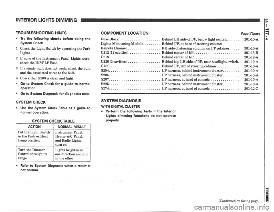
TROUBLESHOOTlNG HINTS COMPONENT LOGATlON Page-Figure
a Try the following checks before doing the Fuse Block. ..................... Behind LN side of IIP, below light switch. ...... 201-10-A
System Check. Lights Monitoring Module. ........ Behind IIP, at base of steering column
................. ..... 1. Check the Light Switch by operating the Park RN
side of steering column, on IIP retainer 201-10-A
................ ........................ Lights. 6212 (12-cavities) Behind center of IIP 201-13-B -
.......................... ........................ 2. If none of the Instrument Panel Lights work, C218. Behind center of IIP 201-12-A
................. check the INST LP Fuse. C220 (2 cavities) Behind top LH side of IIP, near headlight switch. 201-10-A
............ 6200 .......................... Behind IIP, left of steering column 201-10-A
3. If a single light does not work, cheek the bulb ........ S204. .......................... IIP harness, behind instrument cluster. 201-10-A and the associated wires to the bulb. ........ S205. .......................... IIP harness, behind instrument cluster. 201-10-A
4. Check that 6200 is clean and tight. ............... S207. .......................... IIP harness, at head of console. 201-10-A
@ Go to System Check for a guide to normal S225. .......................... IIP harness, behind instrument cluster. ........ 201-10-A
operation. $274. .......................... IIP harness, at head of console. ............... 201-12-C
s Go to System Diagnosis for diagnostic tests.
SYSTEM CHECK SYSTEM DIAGNOSIS
Use the System Check Table as a guide to WITH DIGITAL CLUSTER
normal operation. r Perform
the follbking tests if the Interior
Lights dimming functions do not operate
properly.
SYSTEM CHECK TABLE
ACTION
Put the Light Switch
in the Park or
Head
Lamp position
Refer to System Diagnosis when a result is
not normal.
NORMAL RESULT
Instrument Panel,
Heater-AIC Panel,
and Radio Lights
turn on
Turn the Dimmer
Control through its
range
(Continued on facing page)
Lights brighten
in
one direction and dim
in the other
Page 1600 of 1825
LIGHTING SYSTEMS AND HORNS 8B-I
SECTION 8B
NG SYSTEMS AND HORNS
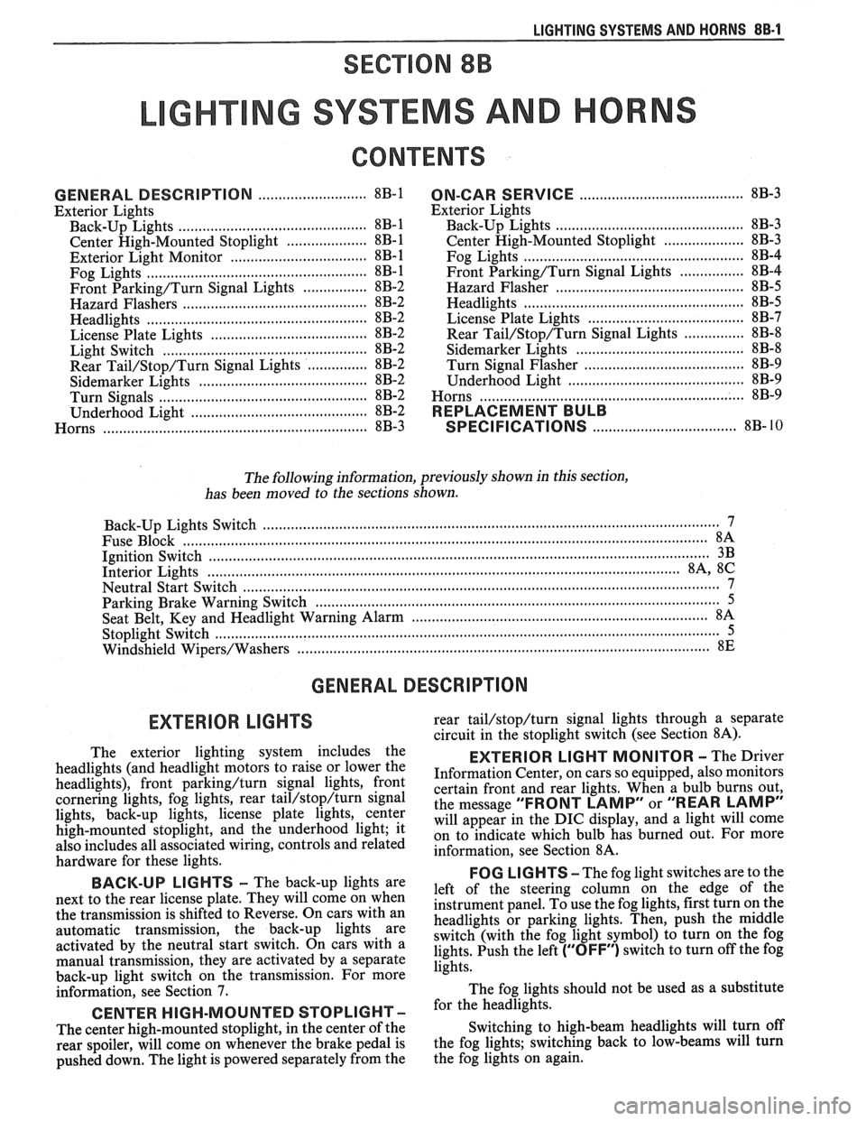
CONTENTS
........................... GENERAL DESCRIPTION 8B-1
Exterior Lights
....................... ................... Back-up Lights .. 8B- 1
Center High-Mounted Stoplight .................... 8B-1
Exterior Light Monitor .................................. 8B-1
............................ .................... Fog Lights .. 8B-1
Front Parking/Turn Signal Lights ................ 8B-2
............................... Hazard Flashers .. ........ 8B-2 .................................................... Headlights 8B-2
License Plate Lights ..................................... 8B-2
Light Switch ............................................... 8B-2
............... Rear Tail/Stop/Turn Signal Lights 8B-2
Sidemarker Lights ........................................ 8B-2
Turn Signals .......................................... 8B-2
......................... Underhood Light ... ........ 8B-2
Horns .......................................................... 8B-3
....................................... ON-CAR SERVICE 8B-3
Exterior Lights
............................................. Back-up Lights 8B-3
Center High-Mounted Stoplight .................... 8B-3
Fog Lights .................................................... 8B-4
Front Parking/Turn Signal Lights ................ 8B-4
Hazard Flasher .............................................. 8B-5
....................................................... Headlights 8B-5
License Plate Lights ..................................... 8B-7
............... Rear Tail/Stop/Turn Signal Lights 8B-8
.......................................... Sidemarker Lights 8B-8
................... ............... Turn Signal Flasher .. 8B-9
......................................... Underhood Light 8B-9
Horns ................................................................. 8B-9
REPLACEMENT BULB
.................................... SPECIFICATIONS 8B- 10
The following information, previously shown in this section,
has been moved to the sections shown.
Back-up Lights Switch
............................. ... ............................................................................ 7
................................................................................................................................. Fuse Block 8A
Ignition Switch ........................................................................................................................... 3B
Interior Lights
................................................................................................................... 8A, 8C
Neutral Start Switch ..................................................................................................................... 7
Parking Brake Warning Switch
......................... ... .................................................................... 5
........................................................................ Seat Belt, Key and Headlight Warning Alarm 8A
Stoplight Switch .......................... .. ............................................................................................... 5
Windshield
Wipers/Washers .................................................................................................... 8E
GENERAL DESCRIPTION
The exterior lighting system includes the
headlights (and headlight motors to raise or lower the
headlights), front
parkinghurn signal lights, front
cornering lights, fog lights, rear
tail/stop/turn signal
lights, back-up lights, license plate lights, center
high-mounted stoplight, and the underhood light; it
also includes all associated wiring, controls and related
hardware for these lights.
BACK-UP LIGHTS - The back-up lights are
next to the rear license plate. They will come on when
the transmission is shifted to Reverse. On cars with an
automatic transmission, the back-up lights are
activated by the neutral start switch. On cars with a
manual transmission, they are activated by a separate
back-up light switch on the transmission. For more
information, see Section 7.
CENTER HIGH-MOUNTED STOPLIGHT-
The center high-mounted stoplight, in the center of the
rear spoiler, will come on whenever the brake pedal is
pushed down. The light is powered separately from the rear
tail/stop/turn signal
lights through a separate
circuit in the stoplight switch (see Section
8A).
EXTERIOR LIGHT MONITOR - The Driver
Information Center, on cars so equipped, also monitors
certain front and rear lights. When a bulb burns out,
the message
"FRONT LAMP" or "REAR LAMP"
will appear in the DIC display, and a light will come
on to indicate which bulb has burned out. For more
information, see Section
8A.
FOG LIGHTS -The fog light switches are to the
left of the steering column on the edge of the
instrument panel. To use the fog lights, first turn on the
headlights or parking lights. Then, push the middle
switch (with the fog light symbol) to turn on the fog
lights. Push the left
("OFF") switch to turn off the fog
lights.
The fog lights should not be used as a substitute
for the headlights.
Switching to high-beam headlights will turn off
the fog lights; switching back to low-beams will turn
the fog lights on again.
Page 1601 of 1825
88-2 LIGHTING SYSTEMS AND HORNS
The fog lights must be aimed for proper
illumination of the road. Fog light
aim should be
checked: at least once a year; when a new light housing
is installed; or if service or repairs in the front end area
have (or may have) disturbed the fog light mountings.
FRONT PARKING/TURM SIGNAL
LIGHTS - Pushing either side of the instrument panel
switch will turn on the front parking lights. (Pushing
the left side of the switch will also turn on the
headlights.) When the ignition is on and the turn signal
lever is moved, the appropriate front parking light
flashes to signal a turn. Both lights will flash when the
hazard flashers are on.
If the driver's door is opened when the parking
lights are on, a warning tone will sound. For more
information, see Section
8A-77.
HAZARD FLASHERS - The hazard warning
flasher is part of the turn signal circuit. Pushing in the
button (on the right side of the steering column) will
cause the front and rear turn signal lights, and the front
sidemarker lights, to flash. Pull out the collar around
the button to turn off the hazard flashers.
The hazard flashers will work with the ignition
either off or on. When the hazard flashers are on, the
turn signals do not
work.
The hazard flashers will stop flashing and stay on
brightly if the brake pedal is pushed down.
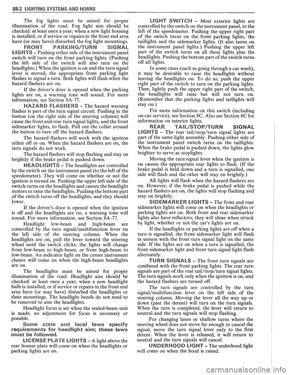
HEADLIGHTS - The headlights are controlled
by the switch on the instrument panel (to the left of the
speedometer). They will come on whether or not the
ignition is turned on. Pushing the upper left side of the
switch turns on the headlights and causes the headlight
motors to raise the headlights. Pushing the bottom part
of the switch turns off the headlights, and they should
lower.
If the driver's door is opened when the ignition
is off and the headlights are on, a warning tone will
sound. For more information, see Section
8A-77.
Headlight low-beam and high-beam are
controlled by the turn
signal/multifunction lever on
the left side of the steering column. When the
headlights are on, pull the lever toward the steering
wheel until the switch clicks; the lights will change
from low-beam to high-beam, or from high-beam to
low-beam. An indicator light on the center instrument
cluster will come on when the high-beam headlights
are on.
The headlights must be aimed for proper
illumination of the road. Headlight aim should be
checked: at least once a year; when a new headlight
bulb is installed; or if service or repairs in the front end
area have (or may have) disturbed the headlights or
their mountings. The headlight bezels do not need to
be removed to aim the headlights.
Headlight focus is set when the sealed-beam unit
is made; no adjustment for focus is necessary or
possible.
Some state and local laws specify
requirements for headlight aim; these laws
must be followed.
LICENSE PLATE LBGHTS -A light above the
rear license plate will come on when the headlights or
parking lights are on.
LIGHT SWITCH - Most exterior lights are
controlled by the switch on the instrument panel, to the
left of the speedometer. Pushing the upper right part
of the switch turns on the front parking lights, the
taillights and the sidemarker lights. (It also turns on
the instrument panel lights.) Pushing the upper left
part of the switch turns on all these lights plus the
headlights. Pushing the bottom part of the switch turns
off all lights.
In some cases (such as going through a car wash),
it may be desirable to raise the headlights without
leaving the headlights on. To do so, push the upper
right part of the switch to turn on the parking lights.
Then, lightly push the upper right part of the switch;
the headlights will raise but will not turn on.
(Remember that the parking lights and taillights will
stay on.)
For more information on this switch (including
on-car service), see Section
8C. Also see Section 8C for
information on interior lights.
REAR TAlL/STOP/TURN SIGNAL
LIGHTS - The rear tail/stop/turn signal lights are
part of the same light assembly. Pushing either side of
the instrument panel switch turns on the taillights.
When the brake pedal is pushed down, the lights glow
brighter to serve as stoplights.
Moving the turn signal lever when the ignition is
on causes the appropriate rear lights to flash. (If the
brake pedal is held down and a turn is signalled, one
side will flash and the other will stay on brightly.)
All lights will flash when the hazard flashers are
on. However, if the brake pedal is pushed while the
hazard flashers are on, the lights will stop flashing and
stay on brightly.
SIDEMARKER LIGHTS -The front and rear
sidemarker lights will come on when the headlights or
parking lights are on. Both front and rear sidemarker
lights also have reflectors; they will shine when struck
by light, whether or not the car's lights are on.
If the headlights or parking lights are off when a
turn is signalled, the front sidemarker light will flash
in unison with the front turn signal light on the same
side. If the lights are on when a turn is signalled, the
front
sidemarker light and front turn signal light flash
alternately.
TURN SlG N ALS - The front turn signals are
combined with the front parking lights. The rear turn
signals are part of the rear
tail/stop/turn signal lights.
The turn signals work only when the ignition is on, and
the hazard flashers are turned off.
The turn signals are controlled by the turn
signal/multifunction lever on the left side of the
steering column. Moving the lever all the way up or
down (past the detent) will turn on the turn signals.
When the turn is completed, the lever will return to
neutral and the turn signals will stop flashing.
For changing lanes or shallow turns where the
steering wheel does not move far enough to cancel the
signal, move the turn signal lever only to the first
detent. When the lever is released, it will return to
neutral and the turn signals will cancel.
UNDERHOOD LIGHT - The underhood light
will come on when the hood is raised.
Page 1604 of 1825
I
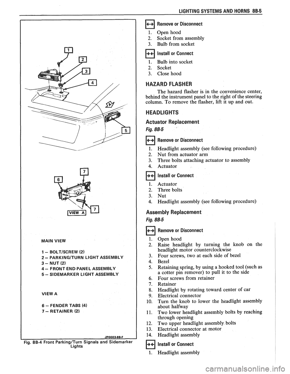
MAIN VIEW
I
1 - BOLTISCREW (2)
2 - PARKINGITURN LIGHT ASSEMBLY
3 - NUT (2)
4 - FRONT END PANEL ASSEMBLY
5 - SIDEMARKER LIGHT ASSEMBLY
VIEW A
6 - FENDER TABS (4)
7 - RETAINER (2)
Fig. 8B-4 Front Parkingflurn Signals and Sidemarker
Lights
LIGHTING SYSTEMS AND HORNS 88-5
Remove or Disconnect
1. Open hood
2. Socket from assembly
3. Bulb from socket
Install or Connect
1. Bulb into socket
2. Socket
3. Close hood
HAZARD FLASHER
The hazard flasher is in the convenience center,
behind the instrument panel to the right of the steering
column. To remove the flasher, lift it up and out.
HEADLIGHTS
Actuator Replacement
Fig. 88-5
Remove or Disconnect
1. Headlight assembly (see following procedure)
2. Nut from actuator arm
3. Three bolts attaching actuator to assembly
4. Actuator
Install or Connect
1. Actuator
2. Three bolts
3. Nut
4. Headlight assembly (see following procedure)
Assembly Replacement
Fig. 88-5
Remove or Disconnect
Open hood
Raise headlight by turning the knob on the
headlight motor counterclockwise
Four screws, two at each side of bezel
Bezel
Retaining spring, by using a hooked tool (such as
a cotter pin remover) to pull it to the side
Four screws from retainer
Retainer
Headlight by rotating toward center of car
Electrical connector
Turn the knob to lower the headlight assembly
about halfway
Two lower headlight assembly bolts by reaching
through opening
Two upper headlight assembly bolts
Electrical connector at motor
Headlight assembly
Install or Connect
1. Headlight assembly