1988 PONTIAC FIERO change time
[x] Cancel search: change timePage 2 of 1825
1988
SER
This manual applies to the 1988 Pontiac Firebird Models.
It contains the latest product information available at the
time of publication approval. lnformation pertaining to
the operation of the vehicle is contained in the Owner's
Manual which accompanies each vehicle. The right is
reserved to make changes at any time without notice.
Any references to brand names in this manual is intended
merely as an example of the types of
lubricant% tools,
materials, etc, recommended for use in servicing 1988
Pontiac Models. In all cases, an equivalent may be used.
PONTIAC DIVISION
GENERAL
MOTORS CORPORATION
PONTIAC, MICHIGAN 48053
1987 General Motors Corp. All Rights Reserved.
No part of this publication may be reproduced, stored in any
retrieval system or transmitted in any form or by any means,
including but not limited to electronic, mechanical,
photocopying, recording or otherwise, without the prior written
permission of General Motors Corp. This includes all text,
illustrations, tables and charts.
S-881 OF 9-87 Printed in Canada
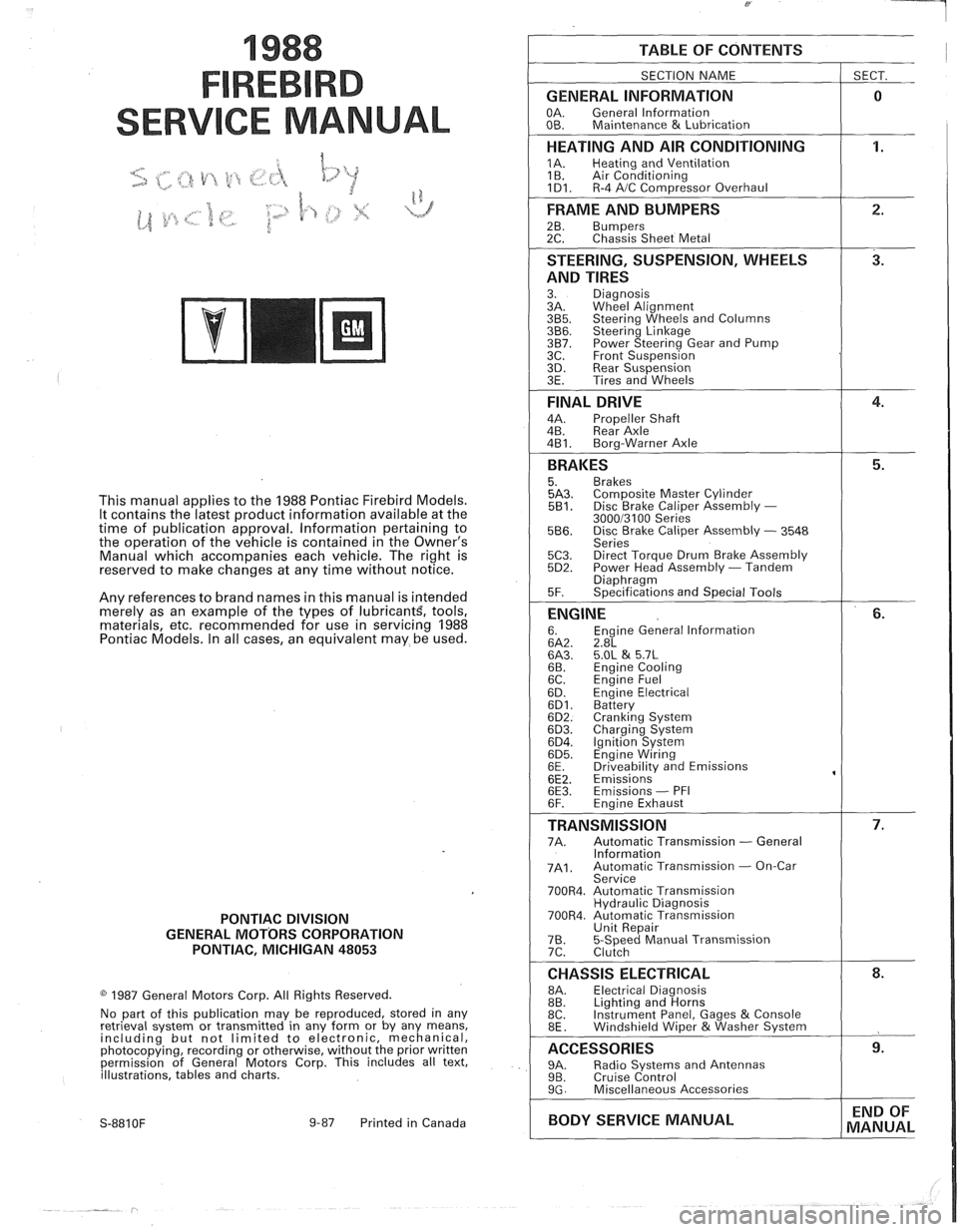
TABLE OF CONTENTS
SECTION NAME
GENERAL INFORMATION
OA. General lnformation
OB. Maintenance & Lubrication
1 SECT.
HEATING AND AIR CONDITIONING
1A. Heating and Ventilation
1 B. Air Conditioning
1D1. R-4 AIC Com~ressor Overhaul
FRAME AND BUMPERS
2B. Bumpers 2C. Chassis Sheet Metal
STEERING, SUSPENSION, WHEELS
AND TIRES
3. Diagnosis
3A. Wheel Alignment
3B5. Steering Wheels and Columns 3B6. Steering Linkage 3B7. Power Steering Gear and Pump
3C. Front Suspension
3D. Rear Suspension
3E. Tires and Wheels
FINAL DRIVE
4A. Propeller Shaft
4B. Rear Axle
4B1. Bora-Warner Axle
BRAKES 5. Brakes 5A3. Comoosite Master Cvlinder 5B1. Disc r rake Caliper ~ssembly - 300013100 Series 5B6. Disc Brake Caliper Assembly - 3548
Series
5C3. Direct Torque Drum Brake Assembly 5D2. Power Head Assembly - Tandem Diaohraam 5F. ~~ecifications and Special Tools
ENGINE 6. Engine General lnformation 6A2. 2.8L 6A3. 5.OL & 5.7L 6B. Engine Cooling
6C. En~ine Fuel
6D. ~ngine Electrical 6D1. Battery 6D2. Cranking System 6D3. Charging System 6D4. Ignition System 6D5. Engine Wiring
6E. Driveabilitv and Emissions
6E2. ~missions' 6E3. Emissions - PFI
6F. Engine Exhaust
TRANSMISSION 7A. Automatic Transmission - General
lnformation
7A1. Automatic Transmission - On-Car
Service
700R4. Automatic Transmission Hydraulic Diagnosis
700R4. Automatic Transmission Unit Repair
76. 5-Speed Manual Transmission
7C. Clutch
CHASSIS ELECTRICAL 8A. Electrical Diagnosis
8B. Lighting and Horns
8C. Instrument
Panel, Gages
& Console
8E. Windshield Wiper &Washer System
ACCESSORIES 9A. Radio Systems and Antennas 9B. Cruise Control 9G. Miscellaneous Accessories
I BODY SERVICE MANUAL END
OF
MANUAL
Page 21 of 1825
OB-4 MAINTENANCE AND LUBRICATION
Tire and wheel operation - Be alert to a vibra-
tion of the steering wheel or seat at normal highway
speeds. This may mean a wheel balance is needed. Also, a
pull right or left on a straight, level road may show the
need for
a tire pressure adjustment or wheel alignment.
Steering system operation - Be alert to
changes in steering action. An inspection is needed when
the steering wheel is harder to turn or has too much free
play or if unusual sounds are noted when turning or
parking.
Headlight aim operation - Take note of light
pattern occasionally. If beam aim doesn't look right,
headlights should be adjusted.
AT EACH FUEL FILL
Engine oil level check - Check engine oil level
and add if necessary. See your Owner's
Manual for further
details.
NOTICE: A large loss in this system may indicate a
problem. Have it inspected and repaired at once.
Engine coolant level and condition - Check
engine coolant level in coolant reservoir tank and add if
necessary. Replace if dirty or rusty. See your Owner's
Manual for further details.
NOTICE: A large loss in this system may indicate a
problem. Have it inspected and repaired at once.
Windshield washer fluid level check -- Check
washer fluid level in container and add if necessary.
Hood latch operation - When opening hood on
cars equipped with hoods that open from the front, note
the operation of secondary latch. It should keep hood from
opening all the way when primary latch is released. Make
sure that hood closes firmly.
AT LEAST MONTI-ILY
Tire and wheel inspection and pressure
check--
Check tires for abnormal wear or damage. Also,
check for damaged wheels. Keep pressures as shown on
Tire Placard on the driver's door (include spare unless it is
a stowaway). Pressure should b\: checked when tires are
"cold". See "Tires" in Owner's Manual for further
infomation.
Light operation check - Check operation of
license plate light, side-marker lights, headlights includ-
ing high beams, parking lights, taillights, brake lights.
turn signals, backup lights, instrument panel and interior
lights and hazard warning flashers.
Fluid leak check - After the car has been parked
for a while, inspect the surface beneath the car for water,
oil, fuel or other fluids. Water dripping from the air
conditioning system after use is normal. If you notice fuel
leaks or fumes, the cause should be found and corrected at
once.
AT LEAST TWICE A YEAR (FOR EXAMPLE,
EVERY SPRING AND FALL)
Power steering pump fluid level check --
Check power steering pump fluid level in accordance with
Owner's Manual instructions and keep at proper level.
NOTICE: A large loss in this system may indicate a
problem. Have it inspected and repaired at once.
Brake master cylinder reservoir fluid level
check ---- Check fluid and keep at proper level. Note: It is
normal for the brake fluid level to go down slightly as the
brake pads wear
- so be sure to keep reservoir filled.
NOTICE: A large loss in this system may indicate a
problem. Have
it inspected and repaired at once.
Clutch system service --- manual transmis-
sionltransaxle --- For cars equipped with hydraulic
clutch system, check the reservoir fluid level and add fluid
as required. All others, check clutch pedal free travel and
adjust as necessary. See your Owner's Manual for further
details.
~
NOTICE: A large loss in this system may indicate a
problem. Have it inspected and repaired at once.
Weatherstrip Lubrication - Clean surface and
then apply a thin film of silicone grease with a clean cloth.
EACH TIME OIL IS CHANGED
Automatic and manual transmissionltrans-
axle fluid level check - Check transmission/transaxle
fluid level and add as required. (Corvette only) if equipped
with manual transmission
- check fluid in the overdrive
unit and add as required.
NOTICE: A large loss in this system may indicate a
problem. Have
it inspected and repaired at once.
Brake systems inspection - For convenience,
the following should be done when wheels are removed
for rotation: Inspect lines and hoses for proper hookup,
binding, leaks, cracks, chafing, etc. Inspect disc brake
pads for wear and rotors for surface condition. Also in-
spect drum brake linings for wear and cracks. Inspect
other brake parts, including drums, wheel cylinders, park-
ing brake, etc. at the same time. Check parking brake
adjustment.
INSPECT BRAKES MORE OFTEN IF DRIVING
HABITS OR CONDITIONS RESULT IN FREQUENT
BRAKING.
Steering, suspension and front drive axle
boot and seal inspection
- Inspect front and rear
suspension and steering system for damaged, loose or
missing parts, signs of wear or lack of lubrication. Inspect
power steering lines and hoses for proper hookup, bind-
ing, leaks, cracks, chafing, etc. (On cars equipped with
manual steering gear, check for seal leakage.) On
front-
wheel-drive cars, clean then inspect drive axle boot seals
for damage, tears or leakage. Replace seals if necessary.
Exhaust system inspection - Inspect complete
system. Inspect body near the exhaust system. Look for
broken, damaged, missing or out-of-position parts as well
as open seams, holes, loose connections or other condi-
tions which could cause a heat buildup in the tloor pan or
could let exhaust fumes seep into the trunk or passenger
compartment.
Page 22 of 1825
MAINTENANCE AND LUBRICATION OB-5
Throttle linkage inspection -- Inspect for inter-
ference, binding, damaged or missing parts.
Engine drive belts inspection - Inspect all
belts for cracks, fraying and wear. Adjust or replace as
needed.
Rear axle service (if equipped) - Check gear
lubricant level and add if needed. For cars equipped with a
limited slip rear axle, fluid does not require changing
(except Caprice and Corvette
- change fluid and required
additive at first
7,500 miles (12 500 km). See your
Owner's Manual or "Recommended Fluids
& Lubricants
Chart" in this section.
IF YOU USE YOUR GAR TO PULL A TRAILER,
CHANGE GEAR LUBRICANT EVERY 7,500 MILES
(12 500 KM).
NOTICE: A large loss in this system may indicate a
problem. Have it inspected and repaired at once.
Power antenna - Clean and then lubricate power
antenna mast. The proper lubricant as shown in Figure
OB-2 should be used.
AT LEAST ONCE A YEAR
Lap and shoulder belts condition and opera-
tion
- Inspect belt system, including webbing, buckles,
latch plates, retractors, guide loops and anchors.
Moveable head restraint operation - On cars
with moveable restraints, make sure restraints stay in the
desired position. (See adjustment instructions in your
Owner's Manual.)
Seatback latch and recliner operation on
cars equipped
with recliner seat --- Be sure seat-
backs latch on those cars with folding seats using mechan-
ical latches. Make sure the recliner is holding by pushing
and pulling on the top of the
seatback while it is reclined.
See your Owner's Manual for seat operating information.
Spare tire and jack storage- Be alert to rattles
in rear of car. Make sure the space tire, all jacking equip-
ment, any tire inflator and any covers or doors are securely
stowed at all times. Oil jack ratchet or screw mechanism
after each use.
Key lock service - Lubricate key lock cylinder at
least annually.
Body lubrication service - Lubricate all body
door hinges including the tailgate or hatchback lid (if
equipped). Also lubricate the body hood, fuel door and
rear compartment hinges and latches including interior
glove box and counsel doors, and any folding seat
hardware.
"Fansmissionltransaxle neutral or clutch
starl switch operation
CAUnON: Before pedorming the follow-
ing safety switch check, be sure to have
enough room around the car. Then, firmly
apply both the parking brake (see your
Owner's Manual for procedure) and the
regular brakes. Do not use the accelerator pedal.
If the engine
starls, be ready to turn
off the ignition promptly. Take these pre-
cautions because the car could move
without warning and possibly cause per-
sonal injury or properly damage. On auto-
matic transmissionltransaxle cars, try to
starl the engine in each gear. The starler
should crank only in "Park" or "Neutral."
On manual transmissionltransaxle cars,
place the
shiR lever in "Neutral," push the
clutch halfway and try to starl. The starler
should crank only when the clutch is fully
depressed.
Steering column lock operation
- While
parked, try to turn key to "Lock" in each gear range. The
key should turn to "Lock" only when gear is in "Park" on
automatic or "Reverse" on manual
transmissionltransax-
le. On cars with key release lever, try to turn key toULock"
without depressing the lever. The key should turn to
"Lock" only with the key lever depressed. On all vehicles,
the key should come out only in "Lock."
Parking brake and transmissionltransaxle
"Park" mechanism operation
CAUT1ON:Before checking the holding
ability of the parking brake and automatic
transmissionltransaxle "Park" mecha-
nism, park on a fairly steep hill with
enough room for movement in the down-
hill direction. To reduce the risk of person-
al injury or property damage, be prepared
to apply the regular brakes promptly if the
car begins to move.
To check the parking brake, with the engine running and
transmission/transaxle in "Neutral." slowly remove foot
pressure from the regular brake pedal (until the car is held
by only the parking brake).
To check the automatic transmissionltransaxle "Park"
mechanism holding ability, release all brakes after shift-
ing the transmissionltransaxle to "Park."
ljnderbody flushing - At least every spring,
tlush from the underbody with plain water any corrosive
materials used for ice and snow removal and dust control.
Take care to thoroughly clean any areas where mud and
other debris can collect.
Sediment packed in closed areas
of the vehicle should be loosened before being flushed.
Engine cooling system service - Inspect
coolant and freeze protection. If dirty or rusty, drain, flush
and refill with new coolant. Keep coolant
at the proper
mixture as specified in your Owner's Manual. This pro-
vides proper freeze protection. corrosion inhibitor level
and engine operating temperature. Inspect hoses and re-
place if cracked. swollen or deteriorated. Tighten hose
clamps. Clean outside of radiator and air conditioning
condensor. Wash radiator filler cap and neck.
To help
ensure proper operation. a pressure test of both the cooling
system and cap is also recommended. (See maintenance
schedule charts in Figure
OB-l for the recommended
coolant change interval.)
Page 57 of 1825
18-14 AIR CONDITIONING
HANDLING OF REFRIGERANT LINES AND
FI-INGS
Tighten all tubing connections as shown in
torque chart (Figure 13). INSUFFICIENT OR
EXCESSIVE TORQUE WHEN TIGHTENING CAN
RESULT IN LOOSE JOINTS OR DEFORMED
JOINT PARTS. Either condition can result in refrig-
erant leakage.
All metal tubing lines should be free of dents or
kinks to prevent loss of system capacity due to line
restriction.
@ The flexible hose lines should never be bent to a
radius of less than four (4) times the diameter of
the hose.
@ The flexible hose lines should never be allowed
to come within a distance of
63.5mm (2-112") of
the exhaust manifold.
@ Flexible hose lines should be inspected regularly
for leaks or brittleness and replaced with new
lines if deterioration or leaking is found.
@ When disconnecting any fitting in the refrigera-
tion system, the system must first be discharged
of all Refrigerant- 12. Proceed very cautiously
regardless of gauge readings. Open very slowly,
keeping face and hands away so that no injury
can occur if there happens to be liquid
Refriger-
ant-12 in the line. If pressure is noticed when
fitting is loosened, allow it to bleed off as
described under DISCHARGING, ADDING
OIL, EVACUATING AND CHARGING PRO-
CEDURES FOR
A/C SYSTEMS.
@ In the event any refrigerant line is opened to the
atmosphere, it should be immediately capped or
taped to prevent entrance of moisture and dirt,
which can cause internal compressor wear or
plugged lines, in the condenser and evaporator
core and expansion (orifice) tubes or compressor
inlet screens.
@ The use of the proper wrenches when making
connections on O-ring fittings is important. The
opposing fitting should always be backed up
with a wrench to prevent distortion of connecting
lines or components. When connecting the flexi-
ble hose connections, it is important that the
swaged fitting and the flare nut, as well as the
coupling to which it is attached, be held at the
same time using three
(3) different wrenches to
prevent turning the fitting and damaging the
ground seat.
@ O-rings and seats must be in perfect condition. A
burr or piece of dirt may cause a refrigerant leak.
When replacing the O-ring, first dip it in clean
525 viscosity refrigeration oil.
MAINTAINING CHEMICAL STABILITY IN
THE
REFRIGERATION SYSTEM
The efficient operation and life of the air condi-
tioning system is dependent upon the chemical stabil-
ity of the refrigeration system. When foreign materials, such as
dirt, air, or moisture, contaminate
the refrigeration system, they will change the stability
of the Refrigerant-12 and 525 viscosity compressor
oil. They will also affect pressure-temperature rela-
tionship, reduce efficient operation and possibly cause
interior corrosion and abnormal wear of moving parts.
The following general practices should be
observed to insure chemical stability in the system:
1. Before disconnecting a refrigerant connection,
wipe away any dirt or oil at and near the connec-
tion to reduce the possibility of dirt entering the
system. Both sides of the connection should be
capped, plugged or taped as soon as possible to
prevent the entry of dirt, foreign material and
moisture.
2. Keep tools clean and dry. This includes the
manifold gauge set and replacement parts.
3. When adding 525 viscosity refrigerant oil (see
ADDING OIL in the DISCHARGING,
ADDING OIL, EVACUATING AND
CHARGING PROCEDURES FOR
AIC SYS-
TEMS, the transfer device and container should
be clean and dry to assure that refrigeration oil
remains as moisture-free as possible.
4. When it is necessary to "open" an
AIC system,
have everything needed ready and handy so that
as little time as possible will be required to per-
form the operation. Do not leave the
AIC system
open any longer than is necessary.
5. Any time the
A/C system has been "opened," it
should be properly evacuated before recharging
with Refrigerant- 12 according to the DIS-
CHARGING, ADDING OIL, EVACUATING
& CHARGING PROCEDURES FOR AIC
SYSTEMS.
All service parts are dehydrated and sealed
prior to shipping. They should remain sealed until just
prior to making connections. All parts should be at
room temperature before uncapping. (This prevents
condensation of moisture from the air entering the
system.) If, for any reason, caps are removed but the
connections are not made, parts should be resealed as
soon as possible.
DISCHARGING, ADDING OIL,
EVACUATING AND CHARGING
PROCEDURES FOR NC SYSTEMS
The refrigerant system may be discharged,
evacuated and charged using air conditioning service
charging station J-23500-01 or equivalent, or the
manifold and gauge set
5-23575-01 and 420ml (14
oz.) disposable cans of Refrigerant-12 (Figure 16).
Charging lines from the charging station or
manifold and gauge set require the use of gauge
adapters to connect to the system service fitting.
A
straight gauge adapter 5-5420 and a 90" angle gauge
adapter
5-9459 are available (see A/C Special Tools).
Always wear goggles and wrap a clean cloth
around fittings and connections when doing work that
Page 195 of 1825
387-2 POWER STEERING
The effect of improperly adjusted worm thrust
bearings or an improperly adjusted over-center preload
could cause a handling stability complaint.
To properly adjust the power steering gear, the
assembly MUST be removed from the vehicle and
adjustments performed as outlined.
For removal of the power steering gear assembly
see "Power Steering Gear".
DRIVE BELT TENSION
All drive belt tension specifications can be found
in the Engine Cooling Section 6B.
When adjusting a power steering pump belt,
never pry against the pump reservoir or pull against the
filler neck. Two systems are used for belt adjustment.
On some
models, the pump is loosened from the
bracket and moved outward to increase the tension. On
other models, a half-inch square drive hole is located
in the bracket, and this hole is used to rotate the
pump-and-bracket assembly outward to increase belt
tension.
Place belt tension gage, J-23600 or equivalent
midway between the pulleys on drive belt being
checked.
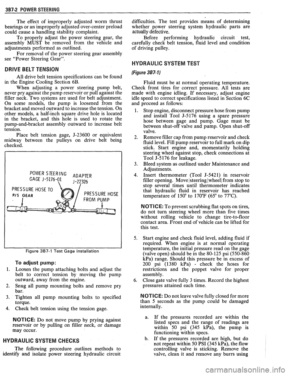
POWER SKERING ADAPER GAGE J-5176-01 J-22326
PRESSURE HOSE TO
P/S GEAR PRESSURE HOSE
Figure 387-1 Test Gage Installation
To adjust pump:
1.
Loosen the pump attaching bolts and adjust the
belt to correct tension by moving the pump
outward, away from the engine.
2. Snug all pump mounting bolts and remove pry
bar.
3. Tighten all pump mounting bolts to specified
torque.
4. Check belt tension using the tension gage.
NOTICE: Do not move pump by prying against
reservoir or by pulling on filler neck, or damage
may occur.
HYDRAULIC SYSTEM CHECKS
The following procedure outlines methods to
identify and isolate power steering hydraulic circuit difficulties.
The test provides means of determining
whether power steering system hydraulic parts are
actually
defective.
Before performing hydraulic circuit test,
carefully check belt tension, fluid level and condition
of driving pulley.
HYDRAULIC SYSTEM TEST
(Figure 387- lj
Fluid must be at normal operating temperature.
Check front tires for correct pressure. All tests are
made with engine idling. If necessary, adjust engine
idle speed to correct specifications listed in Section 6C
and proceed as follows:
1. Stop engine, disconnect pressure hose from pump
and install Tool
5-5176 using a spare pressure
hose between gage and pump. Gage must be
between shut-off valve and pump. Open shut-off
valve.
2. Remove filler cap from pump reservoir and check
fluid level. Fill pump reservoir to full mark on dip
stick. Start engine and, momentarily holding
steering wheel against stop, check connections at
Tool J-5 176 for leakage.
3. Bleed system as outlined under Maintenance and
Adjustments.
4. Insert thermometer (Tool J-5421) in reservoir
filler opening. Move
/steering (wheel/ from stop to
stop several times until thermometer indicates
that hydraulic fluid in reservoir has reached
temperature of
150" to 170°F (65" to 77°C).
N OTI G E: To prevent scrubbing flat spots on tires,
do not turn steering wheel more than five times
without rolling vehicle to change tire-to-floor
contact area. Front end of vehicle can be lifted for
this test.
5. Start engine and check fluid level, adding fluid if
required. When engine is at normal operating
temperature, the initial pressure read on the gage
(valve open) should be in the 80-125 psi (550-860
kPa) range. Should this pressure be in excess of
200 psi (1380
kPa) - check the hoses for
restrictions and the poppet valve for proper
assembly.
6. Close gate valve fully
3 times. Record the highest
pressures attained each time.
N OTI C E: Do not leave valve fully closed for more
than
5 seconds as the pump could be damaged
internally.
a. If
the pressures recorded are within the
listed specs and the range of readings are
within 50 psi (345
kPa), the pump is
functioning within specs.
b. If the pressures recorded are high, but do
not repeat within 50 PSI (345
kPa), the flow
controlling valve is sticking. Remove the
valve, clean it and remove any burrs using
Page 257 of 1825
481-4 REAR AXLE
Gear Noise
Gear noise (whine) is audible from 20 to 55 mph
under four driving conditions:
1. Light Acceleration - Accelerate slowly.
2. Road Load
- Car
driving load or constant speed.
3. Float - Using enough throttle to keep the car from
driving the engine
- car slows down gradually but
engine still pulls slightly.
4. Coast - Throttle closed and car in gear.
Bearing Noise
Bad bearings generally produce more of a rough
growl or grating sound, rather than the whine typical
of gear noise. Bearing noise frequently "wow-wows" at
bearing rpm, indicating a defective pinion or rear axle
case side bearing. This noise could easily be confused
with rear wheel bearing noise. Inspect and replace as
required.
Rear Wheel Bearing Noise
A rough rear wheel bearing produces a noise
which continues with car coasting at low speed and
transmission in neutral. Noise may diminish some by
gentle braking. With rear wheels jacked up, spin rear
wheels by hand while listening at hubs for evidence of
rough (noisy) wheel bearing.
Knock At Low Speeds
Low speed knock can be caused by worn
universal joints or a side gear hub counterbore in a case
that has worn oversize. Inspect and replace universal
joint or case and side gear as required.
Backlash Clunk
Excessive clunk with acceleration and deceleration
is caused by worn differential pinion gear shaft, excessive
clearance between axle shaft and side gear splines, exces-
sive clearance between side gear hub and counterbore in
case, worn pinion and side gear teeth, worn thrust washers
and excessive drive pinion and ring gear backlash. Re-
move worn parts and replace as required, selecting close
fitting parts when possible. Adjust pinion and ring gear
backlash.
DIAGNOSIS
1. Noise
is the same in "Light Acceleration" or
"Coast".
a. Road noise.
b. Tire noise.
c. Front wheel bearing noise.
d. Rear axle bearing noise.
2. Noise changes on a different type of road.
a. Road noise.
b. Tire noise.
3. Noise tone lowers as car speed is lowered.
a. Tire noise.
b. Front
wheel bearings and rear axle bearings.
c. Gear noise.
4. Similar noise is produced with car standing and
driving. a.
Engine noise.
b. Transmission noise.
c. Exhaust noise.
5. Vibration.
a. Rough rear axle bearing.
b. Unbalanced or damaged propeller shaft.
c. Tire unbalance.
d. Worn universal joint in propeller shaft.
e. Mis-indexed propeller shaft at pinion
flange.
f. Pinion flange runout too great.
6. A knock or click approximately every two
revolutions of the rear wheel.
a. A rear axle bearing.
b. Worn case.
7. Noise most pronounced on turns.
a. Rear axle side gear and pinion noise,
differential gear noise.
b. Axle bearings.
8. A continuous low pitch whirring or scraping
noise starting at relatively low speed.
a. All bearing noise.
9. Drive noise, coast noise or float noise.
a. Ring
and pinion gear noise.
b. Front
pinion bearing noise, coast or drive.
c. Axle bearing noise.
10. Clunk
on
acceleration or deceleration.
a. Worn
rear axle pinion shaft splines.
b. Side
gear hub counterbore in case worn
oversize.
c. Worn U-joints.
d. Excessive transmission backlash.
e. Worn axle shaft splines.
11. Chatter on turns.
a. Wrong
lube in rear axle.
b. Clutch
cone worn or spalled.
12. Clunk
or knock on rough road operation.
a. Worn suspension bushings.
PRE-REPAIR INVESTIGATION AND TROUBLE
DIAGNOSIS
A carefull diagnosis of the rear axle prior to
disassembly will often reveal valuable information as to
the extent and type of repairs or adjustments necessary.
Since frequent causes of axle noises are improper
backlash, pinion bearing pre-load, or side bearing
pre-load, or a combination, a few simple adjustments
may be all that are necessary to correct a problem.
Before disassembling the rear axle, the following
checks should be made with the results recorded and
analyzed: 1) Backlash;
2) Total Assembly Preload; 3)
Tooth Contact Pattern Test; 4) Fluid Level; and 5)
Fluid Contamination.
If axle shaft end play is excessive then check
bearings, retainer, and bolts securing backing plate.
The axle bearings could be worn and need replacement.
The four bolts or nuts securing the brake backing plate
may be loose, stripped, or missing. If the inner bearing
retainer worked loose it must be replaced.
Use care at all times to keep dirt and other foreign
matter, such as grinder dust, soot or sand, away from
differential to prevent possibility of subsequent failure.
Page 277 of 1825
4B-4 REAR AXLE
d. Incorrect driveline angle.
Noise changes on a different type of road.
a. Road noise.
b. Tire noise.
Noise tone lowers as car speed is lowered.
a. Tire noise.
Similar noise is produced with car standing and
driving.
a. Engine noise.
b. Transmission noise.
Vibration. a. Rough rear wheel bearing.
b. Unbalanced
or damaged propeller shaft.
c. Tire unbalance.
d. Worn
universal joint in propeller shaft.
e. Incorrect driveline angle.
f. Mis-indexed propeller shaft at pinion
flange.
g. Pinion
flange
runout too great.
A knock or click approximately every two
revolutions of the rear wheel.
a. A rear wheel bearing.
Noise most pronounced on turns.
a. Rear
axle side gear and pinion noise.
A continuous low pitch whirring or scraping
noise starting at relatively low speed.
a. Pinion bearing noise.
Drive noise, coast noise or float noise.
a. Ring and
pinion gear noise.
Clunk on acceleration or deceleration.
a. Worn rear
axle pinion shaft in case or side
gear hub counterbore in case worn oversize.
b. Insufficient
lubrication on propeller shaft
slip yoke.
c. Worn U-joints on
propeller shaft. Front or
rear.
Groan in "Forward" or "Reverse".
a. Wrong
or contaminated lube in rear axle.
b. Worn bushings.
Chatter on turns.
a. Wrong
or contaminated lube in rear axle.
b. Clutch
cone worn and/or
spring(s) worn.
Clunk or knock on rough road operation.
a. Excessive end play of axle shafts to
differential cross shaft.
b. Worn bushings.
PRE-REPAIR INVESTIGATION AND TROUBLE
DIAGNOSIS
A careful1 diagnosis of the rear axle prior to
disassembly will often reveal valuable information as to
the extent and type of repairs or adjustments necessary.
Since frequent causes of axle noises are improper
backlash, pinion bearing pre-load, or side bearing
pre-load, or a combination, a few simple adjustments
may be all that are necessary to correct a problem.
Therefore, before removing the rear axle from the
housing, the following checks should be made with the
results recorded and analyzed:
1) Backlash; 2) Total Assembly
Preload; 3) Tooth Contact Pattern Test;
4)
Fluid Level; and 5) Fluid Contamination.
Use care at all times to keep dirt and other foreign
matter, such as grinder dust, soot or sand, away from
differential to prevent possibility of subsequent failure.
The pinion and ring gear must be completely
assembled, installed and all pre-load and backlash
adjustments completed prior to the start of this method
of pinion depth setting. The following procedure can
be used in place of the gage method of pinion depth
setting.
Gear Tooth Nomenclature
The side of the ring gear tooth which curves
outward, or is convex, is referred to as the "drive" side.
The concave side is the "coast" side. The end of the
tooth nearest center of ring gear is referred to as the
"toe" end. The end of the tooth farthest away from the
center is the "heel" end. Toe end of tooth is smaller
than heel end.
It is very important that tooth contact be tested
before the rear axle carrier assembly is disassembled.
Variations in the carrier or pinion rear bearing may
cause the pinion to be too far away from, or close to,
the ring gear. Thus, the tooth contact must be tested
and corrected, if necessary, or the gears may be noisy.
Tooth Contact Pattern Test
1. Wipe oil out of carrier and carefully clean each
tooth of ring gear.
2. Use gear marking compound part number
1052351 or equivalent and apply this mixture
sparingly to all ring gear teeth, using a medium
stiff brush. When properly used, the area of
pinion tooth contact will be visible when hand
load is applied.
3. Tighten bearing cap bolts to 75
N.m (55 lb. ft.).
4. Expand
brake shoes using parking brake cables
until a torque of 54 to
70 N-m (40-50 lb. ft.) is
required to turn the pinion.
A test made without loading the gears will not
give a satisfactory pattern. Turn pinion flange
with wrench so that ring gear rotates one full
revolution, then reverse rotation so that ring gear
rotates one revolution in opposite direction.
5. Observe
pattern on ring gear teeth and compare
with Fig. 3.
Effects of Increasing Load on Teeth Contact
Pattern
When "load" on ring and pinion gear is
increased, such as when car is accelerated forward
from standstill or from normal drive, the tooth contact
will tend to spread out and, under very heavy load, will
extend from near toe to near heel on the drive side. The
entire contact also tends to shift toward heel under
increasingly heavier loads and will become somewhat
broader with respect to tops and bottoms of teeth. The
patterns obtained by this tooth contact pattern test
approximate a light load and, for this reason, they will
extend only about halfway.
Page 290 of 1825
REAR AXLE 48-1 7
approached. No further tightening should be
attempted until the pre-load has been checked.
7. Check pre-load by using an inch pound torque
wrench.
NOTICE: After pre-load has been checked, final
tightening should be done very carefully. For
example, if when checking, pre-load was found to
be 0.6
N-m (5 lbs. in.), any additional tightening
of the pinion nut can add many additional pound
inch of torque. Therefore, the pinion nut should be
further tightened only a little at a time and the
pre-load should be checked after each slight
amount of tightening. Exceeding pre-load
specifications will compress the collapsible spacer
too far and require the installation of a new
collapsible spacer.
While observing the preceeding note, carefully set
pre-load at 2.7 to 3.6
N-m (24 to 32 1b.in.) on new
bearings or 1.0 to 1.4
N m (8 to 12 1b.in.) on used
bearings.
8. Rotate pinion several times to assure that
bearings have been seated. Check pre-load again.
If pre-load has been reduced by rotating pinion,
reset pre-load to specifications.
Rear Axle Backlash Adjustment
1. Install rear axle case into carrier, using shims as
determined by the side bearing pre-load
adjustment.
2. Rotate rear axle case several times to seat
bearings, then mount dial indicator. Use a small
button on the indicator stem so that contact can
be made near heel end of tooth. Set dial indicator
so that stem is in line as nearly as possible with
gear rotation perpendicular to tooth angle for
accurate backlash reading.
3. Check backlash at three or four points around
ring gear. Lash must not vary over
.05mm (.002")
around ring gear. Pinion must be held stationary
when checking backlash. If variation is over
.05mm (.002") check for burrs, uneven bolting
conditions or distorted case flange and make
corrections as necessary.
4. Backlash at the point of minimum lash should be
between .13 and
.23mm (.005" and ,009") for all
new gears.
5. If backlash is not within specifications, correct by
increasing thickness of one shim and decreasing
thickness of other shim the same amount. This
will maintain correct rear axle side bearing
pre-load.
For each
.03mm (.001") change in backlash
desired, transfer
.05mm (.002") in shim
thickness. To decrease backlash
.03mm (.00lU),
decrease thickness of right shim .05mm (.002")
and increase thickness of left shim .05mm (.
002 "). To increase backlash .05mm (.002 ")
increase thickness of right shim .10mm (.004")
and decrease thickness of left shim .10mm (.
004"). 6.
When backlash is correctly adjusted, remove both
bearing caps and both shim packs.
Keep packs in their respective position, right or
left side.
Select a shim
.10mm (.004") thicker than the one
removed from the left side, then insert left side
shim pack between the spacer and the left bearing
race. Loosely install bearing cap.
7. Select a shim
.10mm (.004") thicker than the one
removed from right side and insert between the
spacer and the right bearing race. It will be
necessary to drive the right shim into position
(Fig. 614).
8. Torque to 75 Nem (55 1b.ft.).
9. Recheck backlash
and correct if necessary.
10. Install axles (See Rear Axle Installation).
11.
Use sealant 1052366 or cover gasket
only.
Install cover and torque cover bolts to 27
N-m (20 1b.ft.).
12. Fill rear axle to proper level with the specified
lubricant. Refer to specifications.
LIMITED SLIP REAR AXLE (GONE TYPE)
The cone-type limited-slip differential has several
definite operating characteristics. An understanding of
these characteristics is necessary as an aid to diagnosis.
The clutch energizing force comes from the
thrust side of the gears. Consequently, a free spinning
wheel may not have enough resistance to drive torque
to apply the clutch cones. If this occurs, apply the
parking brake a few notches which will provide enough
resistance to energize the clutch cones.
Energizing the clutch cones is independent of
acceleration; therefore, a very slow application of the
throttle on starting is recommended to provide
maximum traction by preventing "break away" of
either rear wheel.
Improper operation is generally indicated by cone
slippage or grabbing. Sometimes this produces a
chatter or whirring sound. However, these sounds do
not always indicate failure as they could be produced
from a lack of proper lubrication. For example, under
certain conditions where one wheel is on
a very slippery
surface and the other on dry pavement, wheel spin can
occur if over acceleration is attempted. Continued
spinning may cause audible noise, such as a whirring
sound, due to the cones lacking sufficient lubricant.
This does not necessarily indicate failure of the unit.
During regular operation (straight ahead driving)
when both wheels rotate at equal speeds, there is an
approximately equal driving force delivered to each
wheel. When cornering, the inside wheel delivers extra
driving force causing slippage in both clutch cones.
Consequently, the operational life of the limited slip
unit is dependent upon equal rotation of both wheels
during straight ahead operation. If wheel rotation for
both rear wheels is not equal during straight ahead
operation, the limited-slip unit will constantly be
functioning as if the vehicle were cornering. This will
impose constant slippage on the clutch cones and will
eventually lead to abnormal wear on the clutch cones.
Therefore, it is important that there be no excessive
differences in the rear wheel tire sizes, air pressures, or