1988 PONTIAC FIERO instrument cluster
[x] Cancel search: instrument clusterPage 296 of 1825
BRAKES 5-3
DIAGNOSIS AND INSPECTION
BRAKE SYSTEM TESTING
(Figures
2 through 4)
Brakes should be tested on dry, clean, reasonably
smooth and level roadway. A true test of brake performance
cannot be made if the roadway is wet, greasy or covered
with loose dirt so that all tires do not grip the road equally.
Testing will also be affected if the roadway is crowned
which would throw the weight of the car toward the wheels
on one side. If the roadway is too rough, the wheels will tend
to bounce. Test brakes at different car speeds with both light and
heavy pedal pressure, avoid locking the brakes and sliding
the tires. Locked brakes and sliding tires do not indicate
brake efficiency, because heavily braked, but turning
wheels will stop the car in less distance than locked brakes.
More tire-to-road friction is present with a heavily braked
turning tire than with a sliding tire. The brake system is designed and balanced to avoid
locking the wheels, except at very high deceleration levels.
The shortest stopping distance and best control is achieved
without brake lock-up.
Because of high deceleration capability, a firmer pedal
may be felt at higher deceleration levels.
External Conditions That Affect Brake Performance
1. Tires. Tires having unequal contact and grip on road
will cause unequal braking. Tires must be equally
inflated and tread pattern of right and left tires must
be approximately equal.
2. Car Loading. A heavily loaded car requires more
braking effort. When a car has unequal loading, the
most heavily loaded wheels require more braking
power than others.
3. Wheel Alignment. Misalignment of the wheels, par-
ticularly excessive camber and caster, will cause the
brakes to pull to one side.
4. Front Wheel Bearings. A loose front wheel bearing
BRAKE FLUID LEAKS
With engine running at idle and the transmission in neu-
tral, depress the brake pedal and hold a constant foot pres-
sure.
If the pedal gradually falls away with the constant
pressure, the hydraulic system may be leaking. Perform a
visual check to confirm any suspected leak.
Check the master cylinder fluid levels. While a slight drop
in reservoir level does result from normal lining wear, an
abnormally low level in either reservoir indicates
a leak in
the system. The hydraulic system may be leaking either
internally or externally. See "Master Cylinder Check."
Also, the system may appear to pass this test but still have
slight leakage.
If fluid levels are normal, check the vacuum booster
pushrod length. If an incorrect length pushrod is found,
adjust or replace the
pushrod. Check the service brake
pedal travel and the parking brake adjustment.
When checking the fluid levels, the master cylinder reser-
voir may be as low as
25 mm (1 inch) from the top if the front
linings are worn. This is not abnormal.
MASTER CYLINDER CHECK
These checks will help locate some master cylinder mal-
functions. Use the Brake Diagnosis Charts to help isolate
the problem if it is not found by using these tests.
1. Check for a cracked master cylinder casting or brake
fluid around the master cylinder. Leaks are indicated
only if there is at least a drop of fluid. A damp condi-
tion is not abnormal.
2. Check for a binding pedal linkage.
3. Disassemble the master cylinder and check for swol-
len or stretched piston
seal(s). If swollen seals are
found, substandard or contaminated brake fluid
should be suspected.
If contaminated, all compo-
nents should be disassembled and cleaned. All rub-
ber components should be replaced and all the pipes
should be flushed.
permits the front wheel to tilt and lose contact with the
SUBSTANDARD OR CONTAMINATED brake shoe linings causing erratic brake operation. BRAKE FLUID
WARNING LAMP OPERATION
The brake system uses a single red "BRAKE" warning
lamp located in the instrument panel cluster. When the
ignition switch is in the "START" position, the "BRAKE"
warning lamp should come on. It should go off when the
ignition switch returns to the "RUN" position.
The following conditions will activate the "BRAKE"
warning lamp:
1. Parking brake applied. The lamp should be on when
tfie parking brake is applied and the ignition switch is
"ON."
2. Pressure differential switch detects a failure. See
"Brake Pressure Differential Warning Switch" in this
section. Improper
brake fluid, mineral oil or water in the fluid may
cause the brake fluid to boil or the rubber components to
deteriorate.
If piston cups are swollen, the rubber parts have dete-
riorated. This deterioration may also be seen by swollen
wheel cylinder piston cups on the drum brake wheels or a
swollen master cylinder cover diaphragm.
If rubber deterioration is evident, disassemble all hydrau-
lic parts and wash with alcohol. Dry these parts with com-
pressed air before assembly to keep alcohol out of the
system. Replace all rubber parts in the system, including
hoses. Check for fluid on the linings. If excessive fluid is
found, replace the linings.
If master cylinder piston seals are satisfactory, check for
leakage or excessive heat conditions. If condition is not
found, drain fluid, flush with brake fluid, fill and bleed the
system.
Page 414 of 1825
ENGINE COOLING 88.3
since a small oil pump driven by the separator plate
forces the silicone oil into a reservoir between the
separator plate and the front cover assembly. In this
position, the passage from this cavity to the clutch area
is closed by a slide valve. As operating conditions
produce a high radiator air temperature discharge,
above approximately 66°C
(150"F), the temperature
sensitive bi-metal coil tightens to move the slide valve
(attached to the coil) which opens a port in the
separator plate. This allows a flow of silicone oil into
the clutch chamber to engage the clutch, providing a
maximum fan speed of approximately 2200 rpm. The
clutch coil is calibrated so that, with a road load at an
ambient temperature of approximately 32°C
(90T), the
clutch is just at a point of shift between high and low
fan speed. No attempt should be made to disturb the
calibration of the engine clutch fan assembly as each
assembly is individually calibrated at the time of
manufacture. Under certain temperature conditions
there is a lateral movement at the fan tip which should
not be considered as a hub or bearing failure. This
condition is a design feature of the clutch assembly
which allows up to approximately
1/4" lateral
movement measured at the fan tip.
Testing a clutch fan by holding the small hub
with one hand and rotating the aluminum housing in
a
clockwise/counter-clockwise motion will cause the
clutch to freewheel, which is a normal condition when
operated in this manner. This should not be considered
a test by which replacement is determined.
Temperature Switch
This switch activates a warning lamp in the
instrument cluster if the engine overheats. With
optional instrumentation, a temperature gage replaces
the warning lamp and the temperature switch is
replaced with a transducer. See Section
8A for
Temperature Switch location and diagnosis.
Coolant Temperature Fan Switch
This switch regulates voltage to the coolant fan
relay, which operates the fan whenever the engine
coolant temperature exceeds 230"
F (110" C). For
location and diagnosis see Section 8A for Coolant
Temperature Fan Switch.
Thermostat
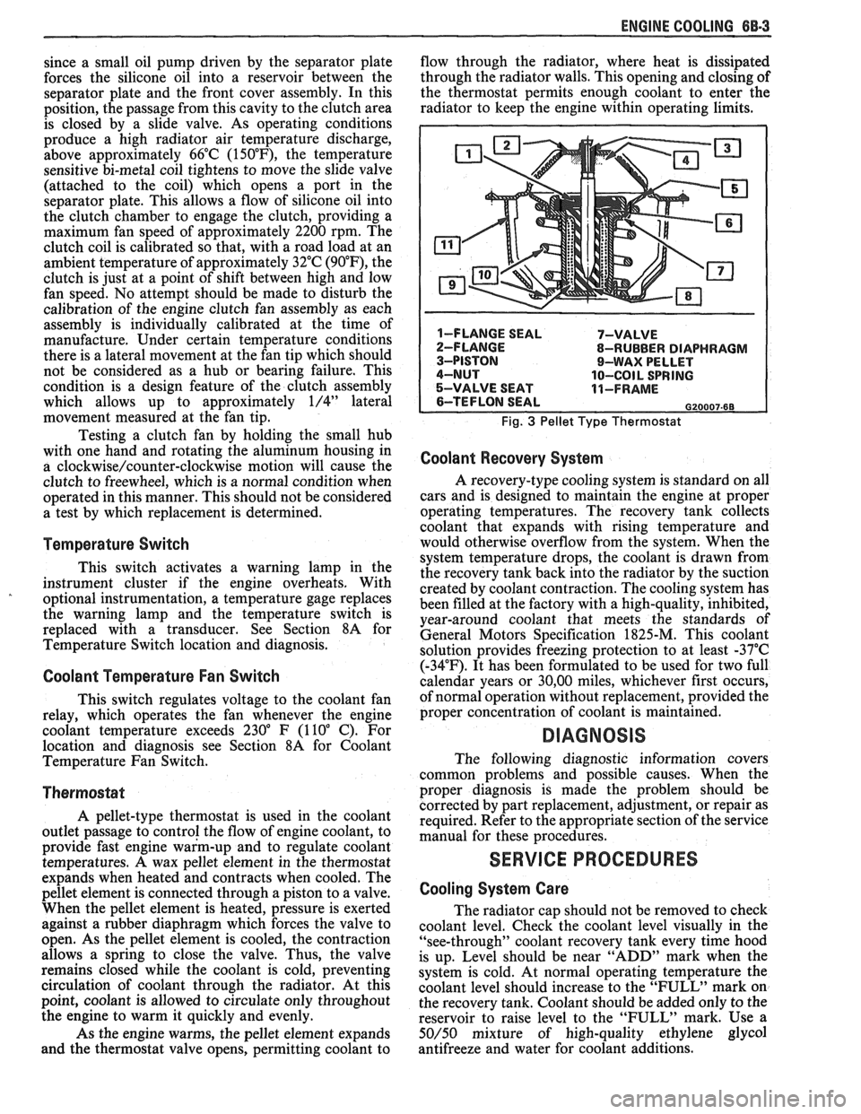
A pellet-type thermostat is used in the coolant
outlet passage to control the flow of engine coolant, to
provide fast engine warm-up and to regulate coolant
temperatures.
A wax pellet element in the thermostat
expands when heated and contracts when cooled. The
pellet element is connected through a piston to a valve.
When the pellet element is heated, pressure is exerted
against a rubber diaphragm which forces the valve to
open. As the pellet element is cooled, the contraction
allows a spring to close the valve. Thus, the valve
remains closed while the coolant is cold, preventing
circulation of coolant through the radiator. At this
point, coolant is allowed to circulate only throughout
the engine to warm it quickly and evenly.
As the engine warms, the pellet element expands
and the thermostat valve opens, permitting coolant to flow
through the radiator, where heat is dissipated
through the radiator walls. This opening and closing of
the thermostat permits enough coolant to enter the
radiator to keep the engine within operating limits.
Fig. 3 Pellet Type Thermostat
Coolant Recovery System
A recovery-type cooling system is standard on all
cars and is designed to maintain the engine at proper
operating temperatures. The recovery tank collects
coolant that expands with rising temperature and
would otherwise overflow from the system. When the
system temperature drops, the coolant is drawn from
the recovery tank back into the radiator by the suction
created by coolant contraction. The cooling system has
been filled at the factory with a high-quality, inhibited,
year-around coolant that meets the standards of
General Motors Specification 1825-M. This coolant
solution provides freezing protection to at least -37°C
(-34°F). It has been formulated to be used for two full
calendar years or
30,OO miles, whichever first occurs,
of normal operation without replacement, provided the
proper concentration of coolant is maintained.
DIAGNOSIS
The following diagnostic information covers
common problems and possible causes. When the
proper diagnosis is made the problem should be
corrected by part replacement, adjustment, or repair as
required. Refer to the appropriate section of the service
manual for these procedures.
SERVICE PROCEDURES
Cooling System Care
The radiator cap should not be removed to check
coolant level. Check the coolant level visually in the
"see-through" coolant recovery tank every time hood
is up. Level should be near "ADD" mark when the
system is cold. At normal operating temperature the
coolant level should increase to the "FULL" mark on
the recovery tank. Coolant should be added only to the
reservoir to raise level to the "FULL" mark. Use a
50/50 mixture of high-quality ethylene glycol
antifreeze and water for coolant additions.
Page 580 of 1825

DRIVEABILITY AND EMISSIONS - 5.OL (\/IN El 6EZ-CZ-5
sent to the ECM. The ECM then increases the injector
base pulse width, permitting increased fuel flow.
As the throttle valve rotates in response to
movement of the accelerator pedal, the throttle shaft
transfers this rotational movement to the
'I'PS. A
potentiometer (variable resistor) within the TPS
assembly changes its resistance (and voltage drop) in
proportion to throttle movement.
By applying a reference voltage (5.0 volts) to the
TPS input, a varying voltage (reflecting throttle
position) is available at the TPS output. For example,
approximately 2.5 volts results from a 50% throttle
valve opening (depending on TPS calibration). The
voltage output from the TPS assembly is routed to the
ECM for use in determining throttle position.
FUEL PUMP
The fuel pump is a turbine type, low pressure
electric pump, mounted in the fuel tank. Fuel
is
pumped at a positive pressure (above 62
kPa or 9 psi)
from the fuel pump through the in-line filter to the
pressure regulator in the TBI assembly Excess
fuel is
returned to the fuel tank through the fuel return line.
The fuel pump is attached to the fuel gage sender
assembly. A fuel strainer is attached to the fuel pump
inlet line and prevents dirt particles from entering the
fuel line and tends to separate
water from the fuel
Vapor lock problems are reduced when using an
electric
pump because the fuel is pushed from the tank
under pressure rather than being pulled
under
vacuum, a condition that produces vapor.
An inoperative fuel pump would cause
a. no start
condition. A fuel pump which does not provide enough
pressure can result in poor performance. (See "Fuel
System Pressure Test" procedure).
FUEL PUMP ELECTRICAL CIRCUIT
When the key is first turned "ON" without the
engine running, the ECM turns the
Fuel pump relay
"ON" for two seconds. This builds
up the fuel pressure
quickly. If the engine is not started within two
seconds, the
ECM shuts the fuel pump "OFF" and
waits until the engine starts. As soon as the engine is
cranked, the ECM turns the relay
"ON" and runs the
fuel pump.
As a backup system to the fuel pump relay, the
fuel pump can also be turned on
by the oil pressure
switch. The oil pressure sender has two circuits
internally. One operates the oil pressure indicator or
gage in the instrument cluster,
itnd the other is
anormally open switch which closes when oil pressure
reaches about 28
kPa (4 psi). If the fuel pump relay
fails, the oil pressure switch will run the fuel pump. An
inoperative fuel pump relay can result in long
cranking times, particularly if the engine is cold. The
oil pressure switch will turn on the fuel pump as soon
as oil pressure
reaches about 28 kPa (4 psi).
FUEL CONTROL
Always start with the "Diagnostic Circuit Check"
in Section
"6E2-A". This will reduce diagnosis time
and prevents unnecessary replacement of parts. The
information in this check will direct diagnosis
concerning "Engine
Crunlis But Won't Run" and the
"Fuel Control System," Section
"6E2-C2", including
diagnosis of an injector, pressure regulator,
fuel pump,
fuel
pump relay, and oil pressure switch.
Idle Air Control (IAC) Valve
A "Scan" tool reads IAC position in steps, calletl
"Counts." "0" steps indicates the ECM is commanding
the
IAC to be driven in, to a fully seiltetl position
(minimum idle air).
The higher the number steps, the
more idle air being allowed to pass
by the IAC valve.
cnose Refer to CHART C-2C for information to cliil,
the function of the IAC valve.
Driva bility
Refer to Section "B" for driveability symptoms
related to the fuel control.
ON-VEHICLE SERVICE
GENERAL SEWVICE INFORMATION
CAUTION:
e To prevent personal injury or damage to the
vehicle
as the result sf an accidental start,
disconnect and reconnect the negative
battery cable before and after service is
performed.
@ Also, catch any fuel that leaks out when
disconnecting the fuel lines, by covering the
fittings with
a shop cloth. Place the cloth in
an approved container when work is
complete.
The 'FBI unit repair procedures cover component
replacement with the unit on the vehicle,
tIowever,
throttle body replacement requires that the complete
unit
be removed from the enginc.
Page 1166 of 1825
CONTENTS
ELECTRICAL DIAGNOSIS
Cell
1
2
3
4 5
10
11
12 14
20
21
22
23
30
31
33
34
40
4
1
60
61
62
63
64
65
66
67
68
Index
Introduction
Symbols
Troubleshooting Procedures Repair Procedures
Power Distribution
Fuse Block Details
Light Switch Details
Ground Distribution
Engine:
V6 VIN S
Engine: V8 VIN
F
Engine: V8 VIN E
Engine:
V8 VIN 8
Starter and Charging System
Coolant Fans
Vehicle Speed Sensor
Cruise Control Horns
Brake Warning System
Heater
Defogger
Air Conditioning: System Check
Air Conditioning: Blower Controls
Air Conditioning: Compressor Controls
Air Conditioning: Air Delivery
Air Conditioning: Blower Controls
Air Conditioning: Compressor Controls
Air Conditioning: Air Delivery Cell
77
8
1
82
86 90
9
1
100
102
103
110
111
112
114
117
120
130
133
134
135
141
143
145
150
151
201 202
203
Warnings and Alarms: Chime
Instrument Panel: Gages Cluster
Instrument Panel:
Digital Cluster
Driver Information Center
(DIC)
WiperlWasher
WiperlWasher: Pulse
Headlights
Headlight Doors
Headlights with Lamp Monitor
Exterior Lights
Exterior Lights with Lamp Monitor
Back Up Lights
Interior Lights
Interior Lights Dimming
Power Windows
Power Door Locks
Theft Deterrent
Hatch Release
Hatch Pull-Down
Power Mirrors
Automatic Day-Night Mirror
Lumbar Support
Radio Power Antenna
Component Location Views
Harness Connector Faces
Harness Routing Views
Page 1167 of 1825
Page
Air Conditioning
Air Delivery
Electronic
.................... 68-0
Manual
....................... 65-0
Blower Controls
Electronic
.................... 66-0
Manual
....................... 63-0
Compressor Controls Electronic
.................... 67-0
Manual
....................... 64-0
................... System Check 62-0
Alarms (Audible)
Chime
......................... 77-0
Antenna(Power) ................... 151-0
Brakes
................. Warning System 41-0
................... Charging system 30-7
...................... Cigar Lighter 114-0
Circuit Breaker Details
PWR ACC Circuit
.......... Breaker 10.1.10.3.10.5.1 1.3
WDO Circuit Breaker
10.1. 10.3. 10.5. 11-4
.......... Component Location Views 201-0
Connectors (Harness Connector Faces) 202-0
el00 .......................... 202-0
............... Junction Block ((2238) 202-2
Coolant Fan
....................... 31-0
Cruise Control
..................... 34-0
Defogger
......................... 61-0
Digital Clock
...................... 150-0
Displays Digital Cluster
.................. 82-0
Coolant Temperature
........... 82-2
Page
......................... Fuel 82-3
................... Oil Pressure 82-2
.................. Speedometer 82-3
................. Door Locks (Power) 130-0
...... Driver Information Center (DIC) 86-0
Engines
... Multi-Port Fuel Injection (VIN S) 20-0
.... Multi-Port Fuel Injection (VIN 8) 23-0
.... Throttle
Body Injection (VIN E) 22-0
...... Tuned
Port Injection (VIN F) 21-0
................. Fuse Block Details 11-0
Fuse Details
........... INST LP 10.0.10.2.10.4.1 1.1
.............. TAIL 10.0.10.2.10.4.1 1.2
................ CRANK 10.0.10.2.1 0.4
.............. CTSY 10~0.10.2.10.4.1 1.2
......... STOP HAZ 10.1.10.3.10.5.1 1.3
............ RADIO 10.1.10.3.10.5.1 1.4
............ WIPER 10.1.10.3.10.5.1 1.4
.................... HATCH 10.2.1 0.4
........... HTR AlC 10.1.10.3.10.5.1 1.4
........... CIH.FAN 10.1.10.3.10.5.1 1.4
......... TURN BIU 10.1.10.3.10.5.1 1.4
............ GAGES 10.1.10.3.10.5.1 1.4
ECM-IGN
(V6 VIN S. V8 VIN F.
........ V8 VIN 8. V8 VIN E) 10.1.1 1.7
............ INJ 1 (V6 VIN S) 10.1.1 1.10
......... FPIINJ 2 (V6 VIN S) 10.1.1 1.10
... INJ 1 (V8 VIN F. V8 VIN 8) 10.3.1 1.11
FPIINJ 2 (V8 VIN F. V8 VIN 8) 10.3.1 1.11
............ CLSTR 10.1.10.3.10.5.1 1.13
............. FPIINJ 2 (V8 VIN E) 11-12
Page
Gages
................... Gages Cluster 81-0
........... Coolant Temperature 81-2
......................... Fuel 81-3
................... Oil Pressure 81-2
.................. Speedometer 81-3
................ Ground Distribution 14-0
Harness Routing Views
............. 203-0
........................... Heater 60-0
............................ Horns 40-0
Indicators
.................. Digital Cluster 82-0
................ Brake Warning 82-4
.................. Fasten Belts 82-1
...................... Hi Beam 82-1
...................... Security 82-1
............ Service Engine Soon 82-4
......................... Shift 82-5
......................... Turn 82-1
................... Gages Cluster 81-0
................ Brake Warning 81-0
.................. Fasten Belts 81-0
...................... Hi Beam 81-0
............ Service Engine Soon 81-0
......................... Shift 81-1
......................... Turn 81-0
Instrument Panel
Digital Cluster
.................. 82-0
Gages Cluster
................... 81-0
............ Interior Lights Dimming 117-0
...................... Introduction 2-0
Lights (Exterior)
........................ Back Up 112-0
...................... Fog 100.3,10 3.0
Page 1169 of 1825
INTRODUCTION 1:
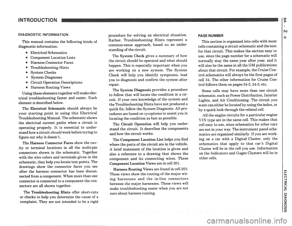
This manual contains the following kinds of
diagnostic information:
e Electrical Schematics
Component Location Lists
@ Harness Connector Faces
@ ?koubleshooting Hints
@ System Checks
System Diagnoses
@ Circuit Operation Descriptions
@ Harness Routing Views
Using these elements together will make elec-
trical troubleshooting faster and easier. Each
element is described below.
The Electrical
Seher~latic should always be
your starting point in using this Electrical
Troubleshooting Manual. The schematic shows
the electrical current paths when a circuit is
operating properly. It is essential to under-
stand how a circuit
should work before trying to
figure out why it doesn't.
The Harness Connector Faces show the cav-
ity or terminal locations in all the multi-pin
connectors shown in the schematic. Together
with the wire colors and terminals given in the
schematic, they help you locate test points. The
drawings show the connector faces you see
after the harness connector has been discon-
nected from a component. When more than one
connector is connected to a component the con-
nectors are all shown together.
The Troubleshooting Hints offer short-cuts
or checks to help you determine the cause of
a
complaint. They are not intended to be a rigid procedure
for solving an electrical situation.
Rather, Troubleshooting Nints represent a
common-sense approach, based on an under-
standing of the circuit.
The System Check gives a summary of how
the circuit should be operated and what should
happen. This is especially important when you
are working on a new system. The System
Check will help you identify symptoms, lead
you to diagnosis and confirm the system after
repair.
The System Diagnosis provides a procedure
to follow that will locate the condition in a cir-
cuit. If your own knowledge of the system and
the Troubleshooting Hints have not produced
a
quick fix, follow the System Diagnosis. All pro-
cedures are based on symptoms to assist you in
locating the condition as fast as possible.
The Circuit Operation will help you under-
stand the circuit. It describes the components
and how the circuit works.
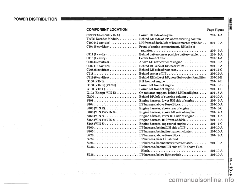
The Component Location List helps you find
where the parts of the circuit are in the vehicle.
A brief statement of the location is given and
also a reference to a drawing that shows the
component and its connecting wires. These
Colnponent Location Views are in cell 201.
Harness Routing Views are found in cell 203.
These views show the routing of the major wir-
ing harnesses and the in-line connectors
between the major harnesses. These views will
make troubleshooting easier when you are not
sure about harness routing.
PAGE NUMBER
This section is organized into cells with most
cells containing a circuit schematic and the text
for that circuit. This makes the section easy to
use, since the page number for a schematic will
normally stay the same year after year, and it
will also be the same in
all the GM publications
about that circuit. For example, the Cruise Con-
trol schematics will always be the first pages of
cell 34. The other information for Cruise Con-
trol follows them on pages
34-2,34-3, etc.
Some cells may have more than one circuit
schematic, such as Power Distribution, Interior
Lights, and Air Conditioning. The circuit you
want can either be located by using the index, or
by a quick look through the related cell.
All the engine circuits for a particular engine
VIN type are in the same cell. This makes that
cell easy to use, since schematics for other cars
are not in your way. The instrument panel sche-
matics are organized similarly. If you are work-
ing on a car with a Digital Cluster, only the
schematics that apply to that car's Digital
Cluster will be in the cell you use. Information
on the Indicators and Gages Clusters will be in
other cells.
Page 1212 of 1825
POWER DISTRIBUTION
COMPONENT LOCATION Page-Figure
Starter Solenoid (VIN
S) .......... Lower RH side of engine ....................
VATS Decoder Module ............ Behind LH side of IIP. above steering column
el00 (42 cavities) ................ LH front of dash. left of brake master cylinder ..
C104 (6 cavities) ................. Front of engine compartment. RH side of
radiator
.................................
Clll(1 cavity) ................... Behind battery. near positive battery cable .....
C115 (1 cavity) ................... Center front of dash ........................
C204 (4 cavities) ................. Above LH rear corner of engine ..............
C207 (15 cavities) ................ Behind RH side of IIP. near ECM .............
C208 (8 cavities) ................. Behind LH side of rear seat ..................
(2218 ........................... Behind center of IIP ........................
C219 (6 cavities) ................. Behind RH side of IIP. near Subwoofer Amplifier
G100 (VIN E) ................... RH front of engine .........................
G100 (VIN F) (VIN 8) ............. Lower LH front of engine ....................
G100 (VIN S) .................... Lower LH front of engine ....................
6103 (Except VIN E) ............. On radiator support. behind LH headlights .....
6200 .......................... Behind IIP. left of steering column ............
S108 ........................... Engine harness. lower RH side of engine .......
S164 ........................... IIPharness. aboveFuseBlock ................
S166 (VIN E) .................... Engine harness. above rear of engine ..........
S166 (VIN F) (VIN 8) ............. Engine harness. above LH rear of engine .......
S166 (VIN S) .................... Engine harness. lower RH side of engine .......
S168 (VIN F) (VIN 8) ............. Engine harness. RH front of dash .............
S168 (VIN S) .................... Engine harness. top rear of engine ............
S200 ........................... IIP harness. behind LH side of IIP ............
S205 ........................... IIP harness. behind instrument cluster .........
S223 ........................... IIP harness. above Fuse Block ................
S224 ........................... IIP harness. near LH shroud
S225
........................... IIP harness. behind instrument cluster .........
S232 ........................... IIP harness. behind LH side of IIP. above Fuse
................................... Block
S236
........................... IIP harness. below light switch ...............
Page 1239 of 1825
GROUND DISTRIBUTION: 6200 :
INSTRUMENT CLUSTER I
A/C - TFMP. A rr