1988 PONTIAC FIERO heater
[x] Cancel search: heaterPage 16 of 1825

- -
GENERAL INFORMATION OA-13
LIST OF AUTOMOTIVE ABBREVIATIONS
WHICH MAY
BE USED IN THIS MANUAL
A-6 - Axial 6 Cyl. A C Compressor AIC - Air Conditioning
ACC - Auto'matic Climate Control
EMF
- Electromotive Force PAIR - Pulse Air Injection Reaction System
EMR - Electronic Module Retard
P B - Power Brakes
EOS - Exhaust Oxygen Sensor
PCV - Positive Crankcase Ventilation
ESC - Electronic Spark Control
PECV - Power Enrichment Control Valve
APT
- Adjustable Part Throttle
AT - Automatic Transmission
ATC - Automatic Temperature Control
ATDC
- After Top Dead Center
FMVSS
- Federal Motor Vehicle Safety BAR0 - Barometric Absolute Pressure Sensor
Ft. Lb. - Foot Pounds (Torque)
Bat. + - Positive Terminal FWD - Front Wheel Drive
- Four Wheel Drive
BHP - Brake Horsepower 4 x 4 - Four Wheel Drive
BP - Back Pressure
BTDC - Before Top Dead Center
HD - Heavy Duty HE1 - High Energy Ignition
Cat. Conv. - Catalytic Converter
CC - Catalytic Converter
- Cubic Centimeter - Converter Clutch
CCC - Computer Command Control
HVM
- Heater-Vent-Module
IAC
- ldle Air Control CCOT - Cycling Clutch (Orifice) Tube IC - Integrated Circuit CCP - Controlled Canister Purge
ID - Identification
C.E. - Check Engine - Inside Diameter
CEAB - Cold Engine Airbleed ILC - Idle Load Compensator
CEMF - Counter Electromotive Force I/P - Instrument Panel
CID - Cubic Inch Displacement ISC - Idle Speed Control CLOOp - Closed Loop
CLCC - Closed Loop Carburetor Control km - Kilometers
CP
- Canister Purge kmiL - Kilometers Liter (mpg) Cu. In. - Cubic Inch kPa - Kilopascals
CV - Constant Velocity
Cyl.
- Cylinder(s)
L-4 - Four Cylinder In-Line (Engine)
DBB - Dual Bed Bead L-6 - Six Cylinder In-Line (Engine)
DBM - Dual Bed Monolith
LF - Left Front DEFl - Digital Electronic Fuel Injection LR - Left Rear DFI - Digital Fuel Injection
Diff. - Differential Man. Vac. - Manifold Vacuum Distr. - Distributor MAP - Manifold Absolute Pressure
EAC
- Electric Air Control Valve
EAS - Electric Air Switching Valve MPG - Miles Per Gallon
ECC - Electronic Comfort Control
MPH - Miles Per Hour
ECM - Electronic Control Module MT - Manual Transmission
N.m - Newton Metres (Torque)
Emission Control
Fig. 014-15 -- Common Abbreviations
Page 24 of 1825
HEATING AND VENTILATION 1A-1
SECTION 1A
NG AND VENT
CONTENTS
General Description ................................. 1A-1
Diagnosis - Heater Trouble ...................... 1A-5
Insufficient Heating or Defrosting .............. 1A-5
Blower Electrical ......................................... 1A-7
....... Improper Air DeliveryINo Mode Shift 1 A-8
Too Much Heat .......................................... 1A-9 ....................................................... Controls 1A-10 ............................................... Blower Noise 1A-11
....................................... On-Vehicle Sewice 1A-13
.......................... Heater Control Assembly 1 A- 13
....................................... Blower Switch 1A- 13
.................................. Temperature Cable
1 A- 13
.......................................... Heater Core 1 A- 13
................................. Vent Control Cable 1 A- 13
Lower Heater Outlet
................................ 1A-14
........................................ Blower Motor 1A-14
GENERAL DESCRIPTION
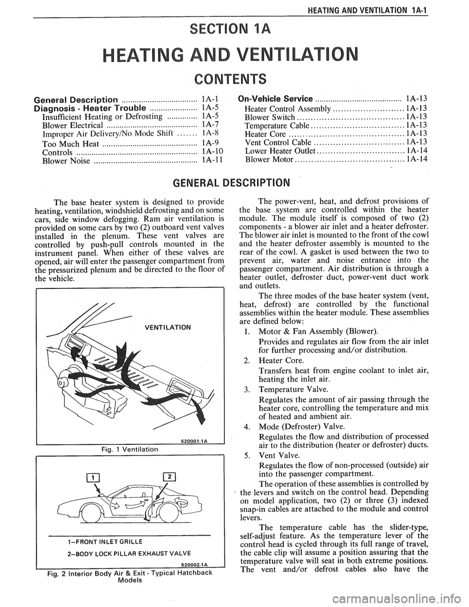
The base heater system is designed to provide
heating, ventilation, windshield defrosting and on some
cars, side window defogging. Ram air ventilation is
provided on some cars by two (2) outboard vent valves
installed in the plenum. These vent valves are
controlled by push-pull controls mounted in the
instrument panel. When either of these valves are
opened, air will enter the passenger compartment from
the pressurized plenum and be directed to the floor of
the vehicle.
/& VENTILATION
1-FRONT INLET GRILLE
2-BODY LOCK PILLAR EXHAUST VALVE
Fig. 2 Interior Body Air & Exit - Typical Hatchback Models
The power-vent, heat, and defrost provisions of
the base system are controlled within the heater
module. The module itself is composed of two (2)
components
- a blower air inlet and a heater defroster.
The blower air inlet is mounted to the front of the cowl
and the heater defroster assembly is mounted to the
rear of the cowl. A gasket is used between the two to
prevent air, water and noise entrance into the
passenger compartment. Air distribution is through a
heater outlet, defroster duct, power-vent duct work
and outlets.
The three modes of the base heater system (vent,
heat, defrost) are controlled by the functional
assemblies within the heater module. These assemblies
are defined below:
1. Motor & Fan Assembly (Blower).
Provides and regulates air flow from the air inlet
for further processing and/or distribution.
2. Heater Core.
Transfers heat from engine coolant to inlet air,
heating the inlet air.
3. Temperature Valve.
Regulates the amount of air passing through the
heater core, controlling the temperature and mix
of heated and ambient air.
4. Mode (Defroster) Valve.
Regulates the flow and distribution of processed
air to the distribution (heater or defroster) ducts.
5. Vent Valve.
Regulates the flow of non-processed (outside) air
into the passenger compartment.
The operation of these assemblies is controlled by
the levers and switch on the control head. Depending
on model application, two (2) or three
(3) indexed
snap-in cables are attached to the module and control
levers.
The temperature cable has the slider-type,
self-adjust feature. As the temperature lever of the
control head is cycled through its full range of travel,
the cable clip will assume a position assuring that the
temperature valve will seat in both extreme positions.
The vent and/or defrost cables also have the
Page 25 of 1825
1A-2 HEATING AND VENTILATION
520003-1 A
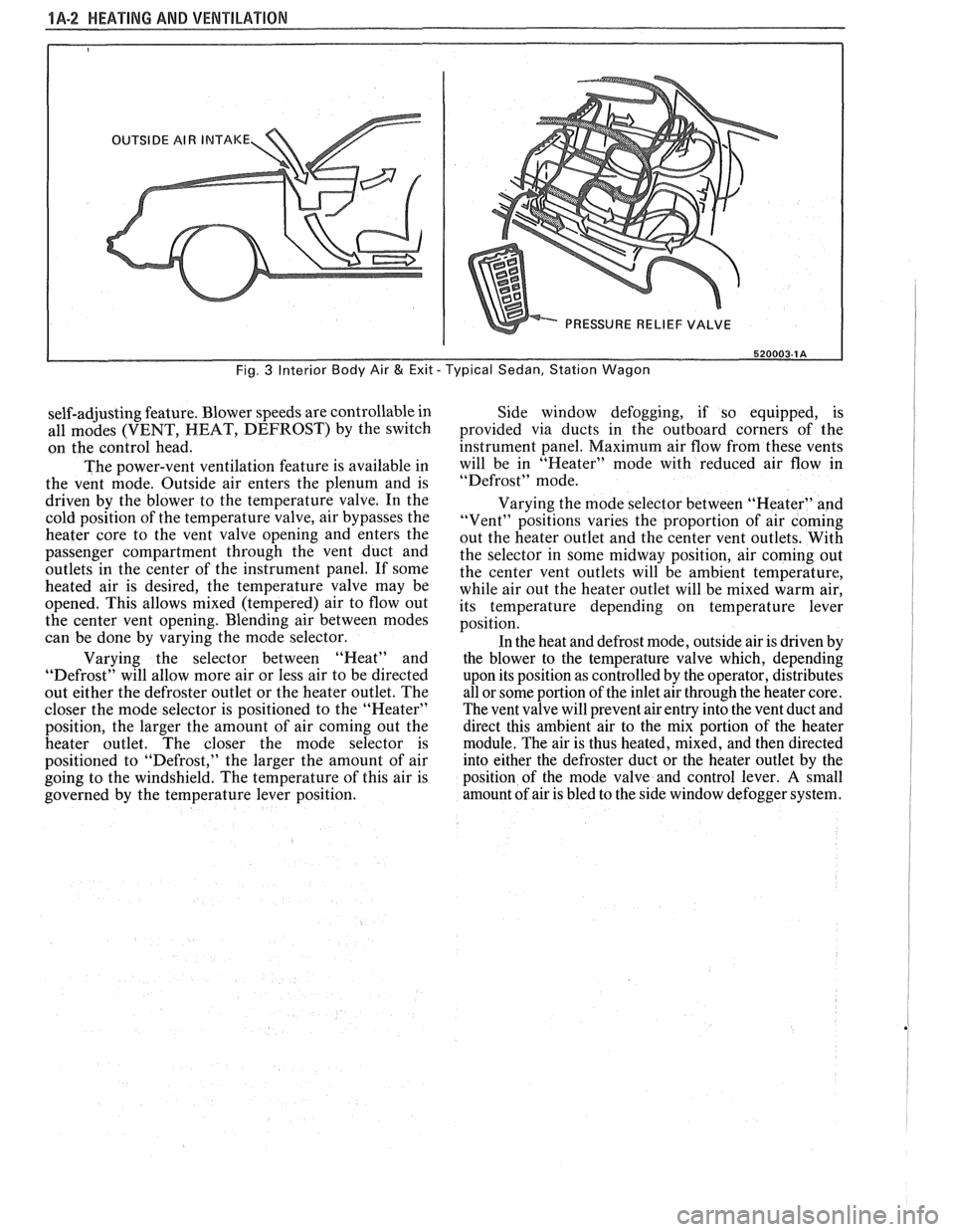
Fig. 3 Interior Body Air & Exit - Typical Sedan, Station Wagon
self-adjusting feature. Blower speeds are controllable in
all modes (VENT, HEAT, DEFROST) by the switch
on the control head.
The power-vent ventilation feature is available in
the vent mode. Outside air enters the plenum and is
driven by the blower to the temperature valve. In the
cold position of the temperature valve, air bypasses the
heater core to the vent valve opening and enters the
passenger compartment through the vent duct and
outlets
in the center of the instrument panel. If some
heated air is desired, the temperature valve may be
opened. This allows mixed (tempered) air to flow out
the center vent opening. Blending air between modes
can be done by varying the mode selector.
Varying the selector between "Heat" and
"Defrost" will allow more air or less air to be directed
out either the defroster outlet or the heater outlet. The
closer the mode selector is positioned to the "Heater"
position, the larger the amount of air coming out the
heater outlet. The closer the mode selector is
positioned to "Defrost," the larger the amount of air
going to the windshield. The temperature of this air is
governed by the temperature lever position. Side window
defogging, if so equipped, is
provided via ducts in the outboard corners of the
instrument panel. Maximum air flow from these vents
will be in "Heater" mode with reduced air flow in
"Defrost" mode.
Varying the mode selector between "Heater" and
"Vent" positions varies the proportion of air coming
out the heater outlet and the center vent outlets. With
the selector in some midway position, air coming out
the center vent outlets will be ambient temperature,
while air out the heater outlet will be mixed warm air,
its temperature depending on temperature lever
position.
In the heat and defrost mode, outside air is driven by
the blower to the temperature valve which, depending
upon its position as controlled by the operator, distributes
all or some portion of the inlet air through the heater core.
The vent valve will prevent air entry into the vent duct and
direct this ambient air to the mix portion of the heater
module. The air is thus heated, mixed, and then directed
into either the defroster duct or the heater outlet by the
position of the mode valve and control lever.
A small
amount of air is bled to the side window defogger system.
Page 26 of 1825
HEAPING AND VENTILA"T0N 1A-3
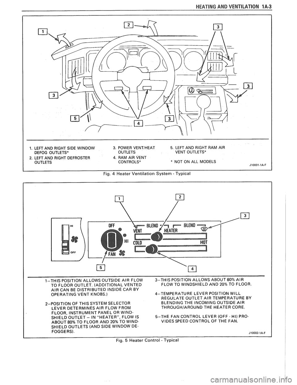
1, LEFT AND RIGHT SIDE WINDOW 3. POWER VENTIHEAT 5. LEFT AND RIGHT RAM AIR
DEFOG OUTLETS* OUTLETS VENT OUTLETS*
2. LEFT AND RIGHT DEFROSTER 4. RAM AIR VENT
OUTLETS CONTROLS* * NOT ON ALL MODELS J10001-1A-F
Fig. 4 Heater Ventilation System - Typical
1-THIS POSITION ALLOWS OUTSIDE AIR FLOW 3-THIS
POSITION ALLOWS ABOUT 80% AIR
TO FLOOR OUTLET. (ADDITIONAL VENTED FLOW
TO WINDSHIELD AND 20% TO FLOOR.
AIR CAN BE DISTRIBUTED INSIDE CAR BY
OPERATING VENT KNOBS.) 4-TEMPERATURE
LEVER POSITION WILL
REGULATE OUTLET AIR TEMPERATURE BY
2-POSITION OF
THIS SYSTEM SELECTOR BLENDING
THE INCOMING OUTSIDE AIR
LEVER DETERMINES AIR FLOW FROM THROUGHIAROUND THE HEATER CORE.
FLOOR, INSTRUMENT PANEL OR WIND-
SHIELD OUTLET - IN "HEATER", FLOW IS 5-THE
FAN CONTROL LEVER (OFF - HI) PRO.
ABOUT
80% TO FLOOR AND 20% TO WIND- VIBES SPEED CONTROL OF THE FAN.
SHIELD OUTLETS (AND
SlDE WINDOW DE-
FOGGERS).
Fig. 5 Heater Control - Typical
Page 27 of 1825
1A-4 HEATING AND VENTILATION
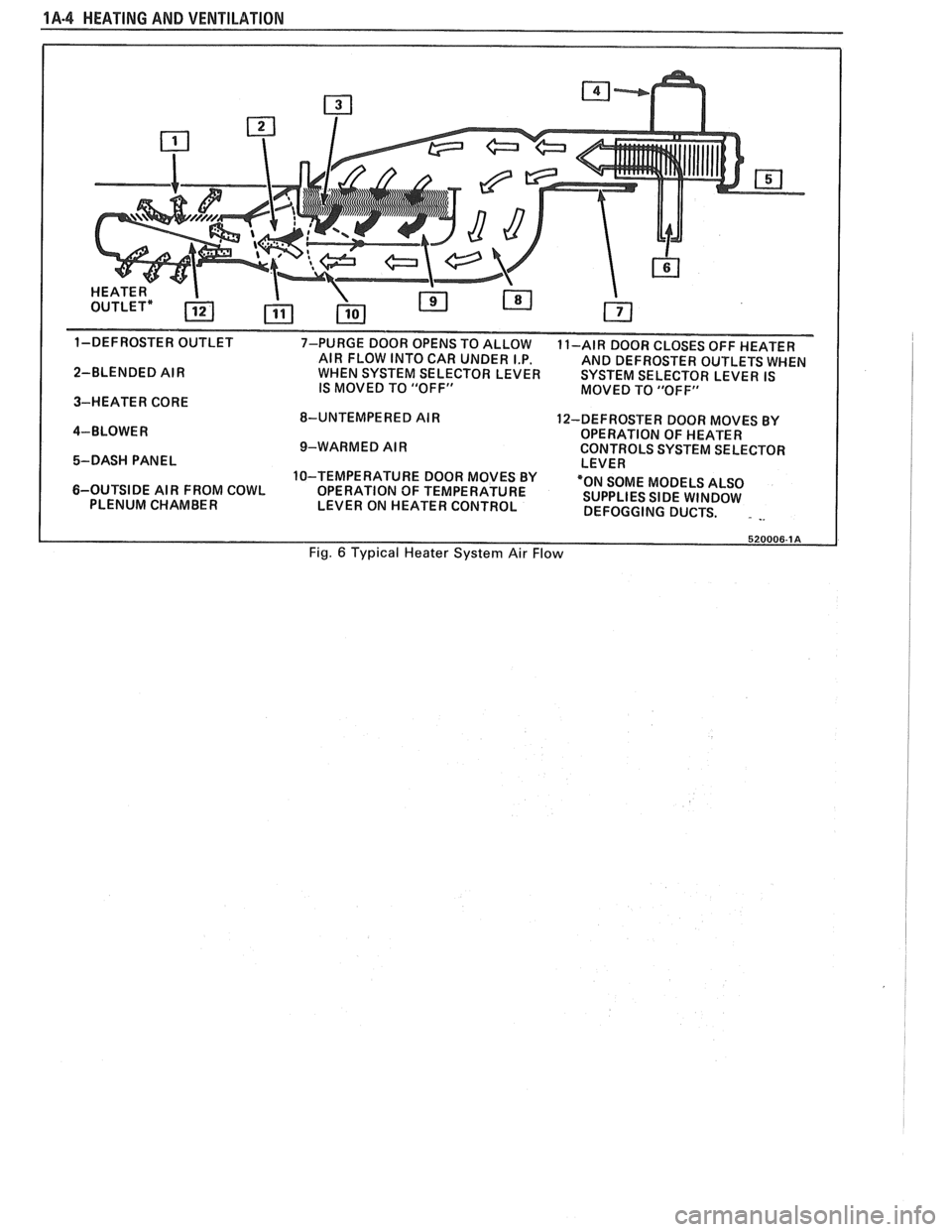
1-DEFROSTER OUTLET
7-PURGE DOOR OPENS TO ALLOW
11-AIR DOOR CLOSES OFF HEATER
AIR FLOW INTO CAR UNDER I.P.
AND DEFROSTER OUTLETS WHEN
2-BLENDED AIR WHEN SYSTEM SELECTOR LEVER SYSTEM SELECTOR LEVER IS
IS MOVED TO "OFF"
MOVED TO "OFF"
3-HEATER CORE
8-UNTEMPERED AIR
12-DEFROSTER DOOR MOVES BY
4-BLOWER OPERATION OF HEATER
9-WARMED AIR CONTROLS SYSTEM SELECTOR
5-DASH PANEL LEVER
10-TEMPERATURE DOOR MOVES BY
6-OUTSIDE AIR FROM COWL
OPERATION OF TEMPERATURE "ON
SOME MODELS ALSO
PLENUM CHAMBER
LEVER ON HEATER CONTROL SUPPLIES
SIDE WINDOW
DEFOGGING DUCTS.
. -.
Fig. 6 Typical Heater System Air Flow
Page 28 of 1825
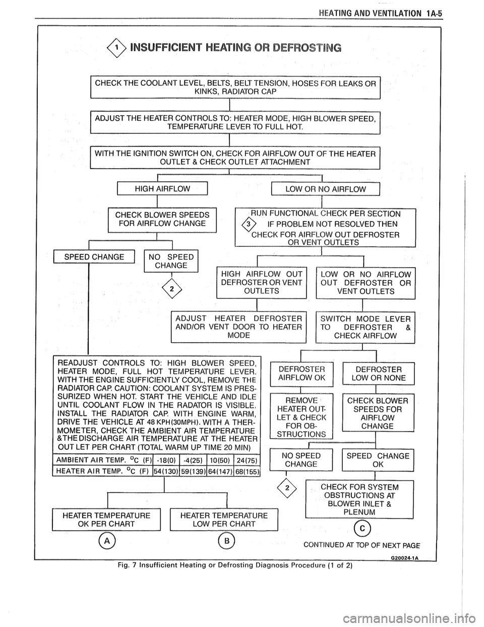
HEATING AND VENTILATION 1A-5
@ INSUFFICIENT HEATING OR DEFROST lNG
OF THE HEATER
IF PROBLEM
NOT RESOLVED THEN
HECK FOR AIRFLOW OUT DEFROSTER
VENT OUTLETS
INSTALL THE RADIATOR CAP. WITH ENGINE WARM,
DRIVE THE VEHICLE AT
48 KPH(3OMPH). WITH A THER-
MOMETER, CHECK THE AMBIENT AIR TEMPERATURE
CONTINUED AT TOP OF NEXT PAGE
Fig. 7 Insufficient Heating or Defrosting Diagnosis Procedure (7 of 2)
Page 29 of 1825
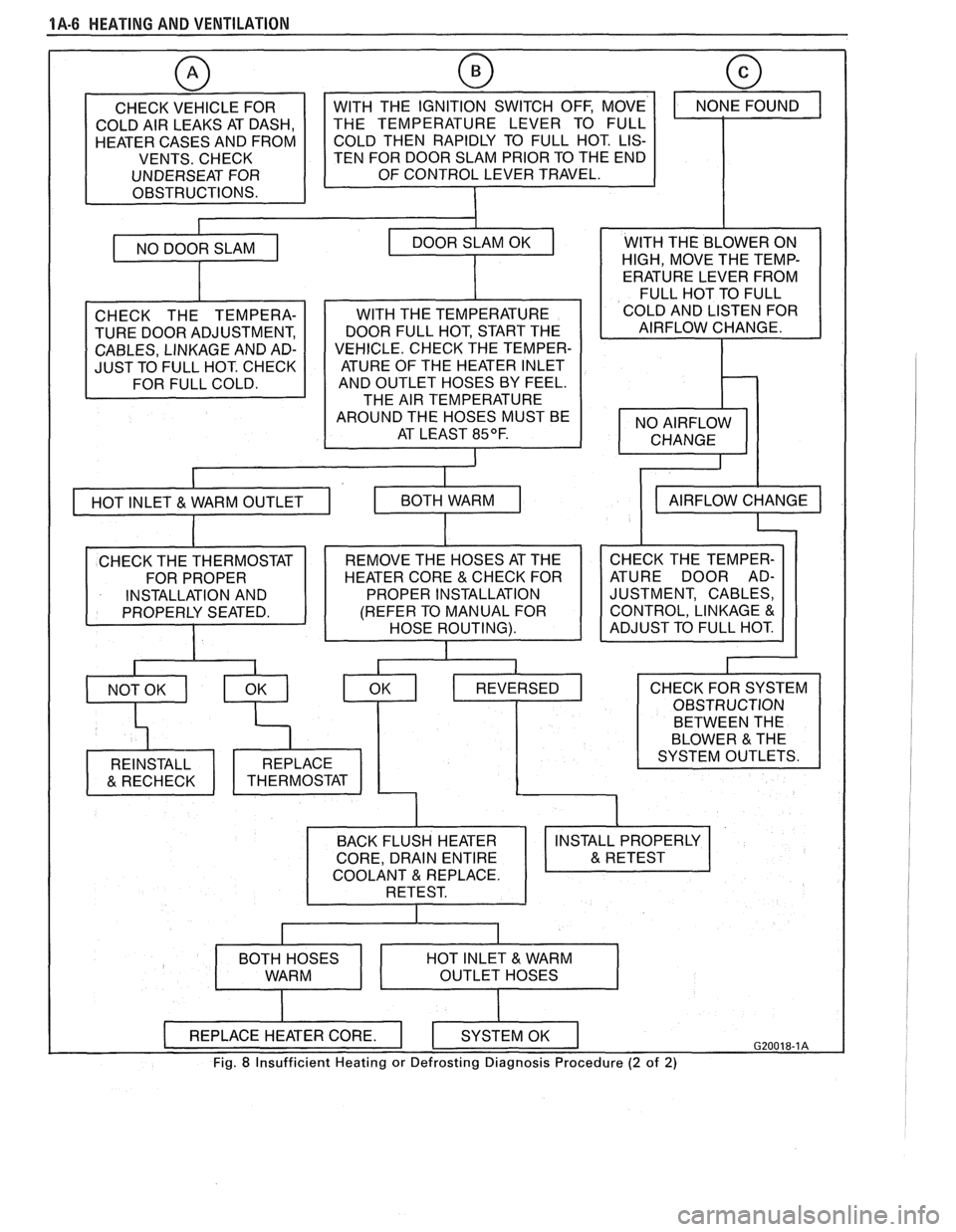
1A-6 HEATING AND VENTILATION
CHECK VEHICLE FOR
COLD AIR LEAKS AT DASH,
HEATER CASES AND FROM
VENTS. CHECK
UNDERSEAT FOR
OBSTRUCTIONS.
w
TEN FOR DOOR SLAM PRIOR TO THE END
CHECK THE TEMPERA-
TURE DOOR ADJUSTMENT,
CABLES, LINKAGE AND AD-
JUST TO FULL HOT. CHECK
I
WITH THE TEMPERATURE
DOOR FULL HOT, START THE
VEHICLE. CHECK THE TEMPER- ATURE OF THE HEATER INLET
AND OUTLET HOSES BY FEEL.
THE AIR TEMPERATURE
AROUND THE HOSES MUST BE AT LEAST
85OF.
I
WITH THE BLOWER ON
HIGH, MOVE THE TEMP-
ERATURE LEVER FROM
FULL HOT TO FULL
COLD AND LISTEN FOR
AIRFLOW CHANGE.
CHECK THE TEMPER-
ATURE DOOR AD-
JUSTMENT, CABLES,
CONTROL, LINKAGE
&
BETWEEN THE
COOLANT REPLACE.
Fig. 8 Insufficient Heating or Defrosting Diagnosis Procedure (2 of 2)
Page 30 of 1825
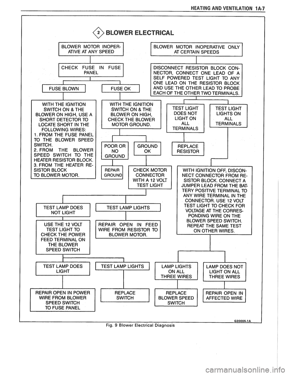
HEATING AND VENTILATION 1A-7
@ BLOWER ELECTRICAL
LOCATE SHORT IN THE
FOLLOWING WIRES:
1. FROM THE FUSE PANEL
2. FROM THE BLOWER
SPEED SWITCH TO THE
HEATER RESISTOR BLOCK.
3. FROM THE HEATER RE-
SISTOR BLOCK. CONNECT A
JUMPER LEAD FROM THE BAT-
TERY POSITIVE TERMINAL TO
ANY
WlRE TERMINAL IN THE
CONNECTOR. USE
12 VOLT
TEST LIGHT TO CHECK FOR
VOLTAGE AT THE CORRES-
PONDING WIRE ON THE
USE THE
12 VOLT
TEST LIGHT TO
CHECK THE POWER
FEED TERMINAL ON
THE BLOWER
SPEED SWITCH
TEST LAMP DOES BLOWER
SPEED SWITCH.
REPAIR OPEN IN FEED
WlRE FROM RESISTOR TO
BLOWER MOTOR.
Fig. 9 Blower Electrical Diagnosis