1988 PONTIAC FIERO heater
[x] Cancel search: heaterPage 42 of 1825
HEATING AND VENTILATION 1A-19
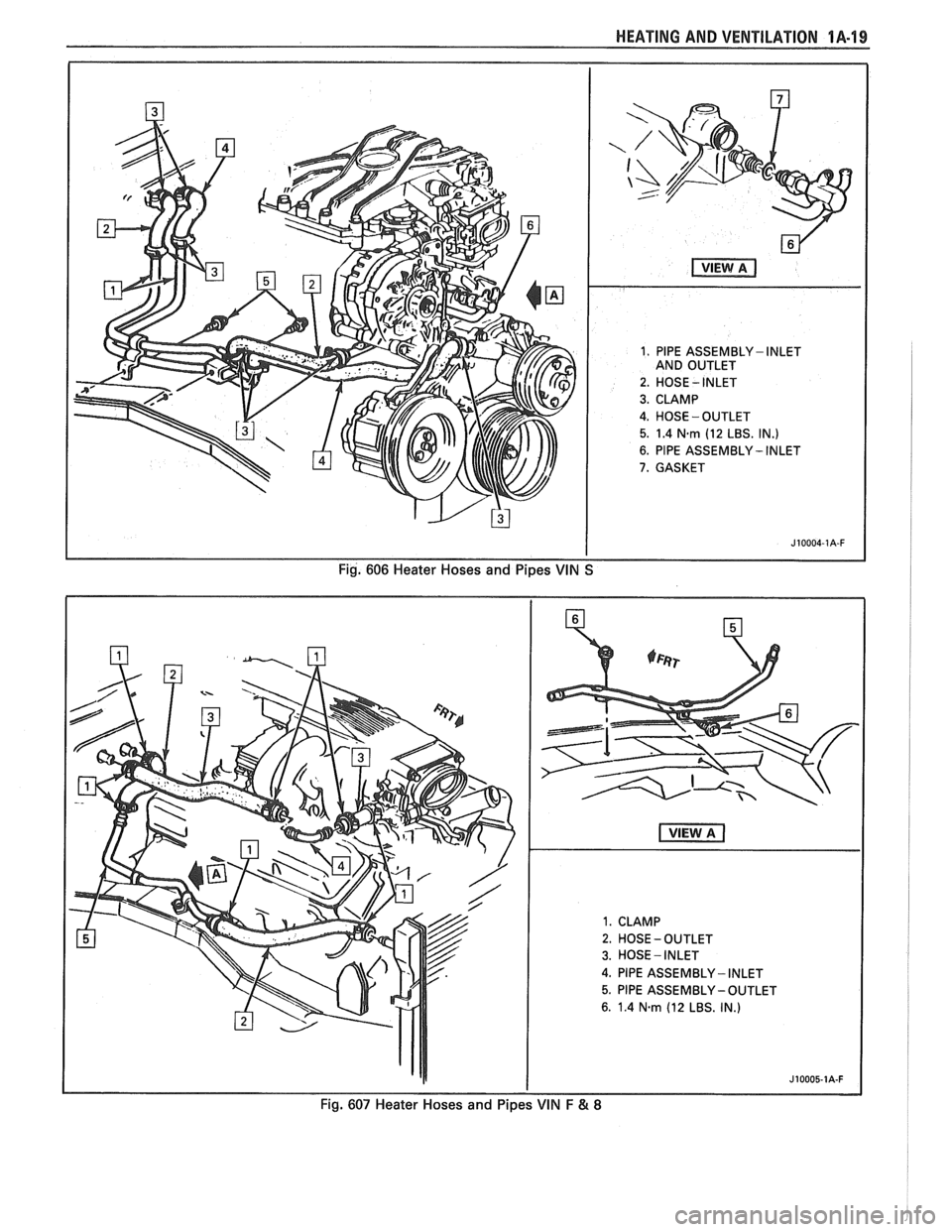
1. PlPE ASSEMBLY - INLET
AND OUTLET
2. HOSE
- INLET
3. CLAMP
4. HOSE -OUTLET
5. 1.4 N.rn (12 LBS. IN.)
6. PlPE ASSEMBLY - INLET
7. GASKET
Fig. 606 Heater Hoses and Pipes VIN S
1. CLAMP
2. HOSE - OUTLET
3. HOSE - INLET
4. PlPE ASSEMBLY - INLET
5. PIPE ASSEMBLY -OUTLET
6. 1.4 N-rn (12 LBS. IN.)
Fig. 607 Heater Hoses and Pipes VIN F & 8
Page 43 of 1825
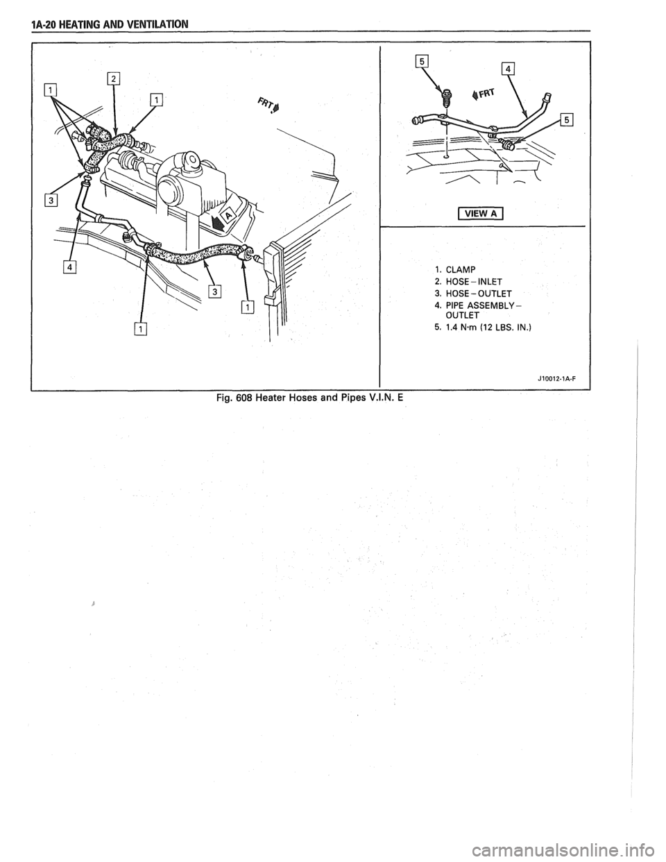
1. CLAMP
2. HOSE
- INLET
3. HOSE - OUTLET
4.
PIPE ASSEMBLY- OUTLET
5. 1.4 N-rn (12 LBS. IN.)
I I Fig. 608 Heater Hoses and Pipes V.I.N. E
Page 44 of 1825
AIR CONDITIONING 1B-1
SECTION 1B
R COND
When performing air conditioning diagnosis on vehicles equipped with a catalytic converter, it will be necessary to
WARM the engine to a NORMAL operating temperature BEFORE attempting to idle the engine for periods greater
than five
(5) minutes. Once the engine attains normal idle, diagnosis and adjustments can be made.
CONTENTS
.................. General Description .................................. 1B-1 Accumulator Assembly Service .1B-19
.......................... C.C.O.T. A!C System ................................ 1B-1 On-Vehicle Sewice ..... 1B-20
....................................... System Components - Functional ................. 1B-2 Blower Motor .1B-20
..................................... System Components - Control ..................... 1B-3 Hi-Blower Relay 1B-20
...................................... Relays and Switches ................................... 1B-3 Blower Resistor 1B-20
Diagnosis ................................................. 1B-5 Controller, Blower Switch or Vacuum
................................................ Testing the Refrigerant System ...................... 1B-5 Valve .lB-20
Insufficient Cooling "Quick-Check Temperature Control Cable ....................... .1B-20
.................................... Procedure.. ............................................. 1B-5 Vacuum
Harness .lB-20
C.C.O.T. A/C System Diagnostic Control Wiring Harness ........................... .1B-20
..... ................................. Procedure.. ............................................. 1B-8 Heater
Core .. .lB-21
................................ Leak Testing ........................................... 1B-12 Lower Heater Outlet 1B-21
............................... Service Procedures ................................. .1B-12 Heater Module Case .lB-21
.......................... O-Ring Replacement ................................ .1B- 12 Pressure Cycling Switch .1B-21
....................................... Handling Refrigerant- 12 ............................ .1B- 13 Vacuum Tank .lB-21
Discharging, Adding Oil, Evacuating Liquid Line .......................................... .1B-23
and
Charging Procedures - AIC Accumulator ......................................... .1B-23
.................................... Systems .............................................. .1B-14 Evaporator Core .1B-24
In-Line Air Conditioning Evaporator Case .................................... .1B-24
.......................................... Filter
Installation.. .................................. .1B- 18 Compressor .lB-24
.............................................
................ Expansion Tube (Orifice) Service .1 B- 19 Condenser IB-24
GENERAL DESCRIPTION
All engines are equipped with a fixed displace- evaporator temperature. The pressure cycling switch
ment (R-4) air conditioning compressor. This
com- is the freeze protection device in the system and
pressor may cycle on and off under normal air
senses refrigerant pressure on the suction side of the
conditioning demand. system. This switch is located on a standard
Schrader- -
All air conditioning systems that use the fixed
displacement R-4 compressor are referred to as
C. C.O.T. (Cycling Clutch, Orifice Tube) type sys-
tems. This is the same system that has been used on
all General Motors vehicles in the past several years.
The C.C.O.T. NG System
The Cycling Clutch Orifice Tube (C.C.O.T.)
refrigeration system is designed to cycle a compressor
on and off to maintain desired cooling and to prevent
evaporator freeze. Passenger compartment comfort is
maintained by the temperature lever on the controller.
Control of the refrigeration cycle (on and off
operation of the compressor) is done with a switch
which senses low-side pressure as an indicator of type
valve low-side fitting. During air temperatures
over 10°C
(50°F), the equalized pressures within the
charged
A/C system will close the contacts of the
pressure switch. When an air conditioning mode
(max, norm, bi-level, defrost) is selected, electrical
energy is supplied to the compressor clutch coil. AS
the compressor reduces the evaporator pressure
to
approximately 175 kPa (25 psi), the pressure switch
will open, de-energizing the compressor clutch.
As
the system equalizes and the pressure reaches approxl-
mately 315 kPa (46 psi), the pressure switch contacts
close, re-energizing the clutch coil. This cycling
coy
tinues and maintains average evaporator discharge air
temperature at approximately 1°C (33°F). Because of
this cycling, some slight increases and decreases of
engine speedlpower may be noticed under certain con-
ditions. This is normal as the system is designed
to
cycle to maintain desired cooling, thus preventing
evaporator freeze-up.
Page 46 of 1825
AIR CONDITIONING 1 B-3
A low-side pressure Schrader valve service fit-
ting is located near the top of the accumulator. A
similar Schrader fitting may be provided for mounting
the pressure cycling switch. It is not necessary to dis-
charge the system to replace the switch. The accumu-
lator is serviced only as a replacement assembly.
Heater Core
The heater core heats the air before it enters the
car. Engine coolant is circulated through the core to
heat the outside air passing over the fins of the core.
The core is functional at all times (no water valve) and
may be used to temper conditioned air in
A/C mode,
as well as heat or vent mode.
SYSTEM COMPONENTS --- CON"FOL
Controller
The operation of the A/C system is controlled by
the switches and the lever on the control head. The
compressor clutch and blower are connected electri-
cally to the control head by a wiring harness. The
blower circuit is open in the off mode and air flow is
provided by the four blower speeds available in the
remaining modes. Cooled and dehumidified air is
available in the max, normal, bi-level and defrost
modes.
Temperature is controlled by the position of the
temperature lever on the control head. A cable con-
nects this lever to the temperature door which controls
air flow through the heater core. As the temperature
lever is moved through its range of travel, a sliding
clip on the cable at the temperature valve connection
should assume a position assuring that the temperature
door will seat in both extreme positions. Temperature
door position is independent of mode selection. The
temperature cable attaches to the right side of the air
conditioning module. The temperature door on some
models is controlled electrically, thereby eliminating
the need for the temperature cable.
The electric engine cooling fan on some cars is
not part of the
A/C system; however, the fan is
operational any time the
A/C control is in Max.,
Norm, or Bi-Level modes. Some models provide for
engine cooling fan operation when the controller is in
the defrost mode. This added feature is part of the
A/C
controller function and is aimed at preventing exces-
sive compressor head temperatures. It also allows the
A/C system to function more efficiently. On some
models during road speed (above
35 mph) conditions
when air flow through the condenser coil is adequate
for efficient cooling, the engine cooling fan will be
turned off. The operation of the cooling fan is con-
trolled by the ECM through the cooling fan relay.
Complete wiring diagrams and diagnosis for the
AIC Electrical System are in Section 8A. Section 8A
also contains additional diagnostic information
regarding air flows and vacuum logic.
Vacuum Lines
Vacuum lines are molded to a connector which
is attached to a vacuum control switch on the control
head assembly.
In case of leakage or hose collapse, it will not be
necessary to replace the entire harness assembly.
Replacement can be made by cutting the hose and
inserting a plastic connector. If an entire hose must be
replaced, cut all hoses off at the connector and then
attach hoses directly to the control head vacuum
switch. (NOTE: The Fiero uses an electric motor to
control mode selection. Therefore, it will not have a
vacuum harness.
)
Vacuum Tank
During heavy acceleration, the vacuum supply
from the carburetor drops. A check valve in the vac-
uum tank maintains vacuum so that, under load condi-
tions, vacuum will be available for continuous use.
REWVS AND SWITCHES
High-Pressure Compresssr Gut-OFF Switch
The high-side, high-pressure cut-off switch in
the rear head of the compressor is a protective device
intended to prevent excessive compressor head pres-
sures and reduce the chance of refrigerant escape
through a safety relief valve. Normally closed, this
switch will open the circuit at a high-side pressure of
approximately 2700
kPa (430 psi 9 20 psi) and
reclose the circuit at approximately 1379 kPa (200 psi
9 50 psi).
Lsw-Pressure Cut-On Switch
Compressor protection is provided on some cars
by a low-pressure cut-off switch which will open in
the event of a low-charge condition. This switch can
be located in the liquid line or in the rear head of the
compressor. This switch will also keep the compres-
sor from running during cold weather.
Pressure eyesing Switch
The refrigeration cycle (on and off operation of
the compressor) is controlled by a switch which
senses the low-side pressure as an indicator of evapo-
rator temperature. The pressure cycling switch is the
freeze protection device in the system and senses
refrigerant pressure on the suction side of the system.
This switch is located on a standard Schrader-type
valve low-side fitting. This switch also provides com-
pressor cut-off during cold weather.
Additional compressor protection results from
the operating characteristics of the low-side pressure
cycling system. If a massive discharge occurs or the
orifice tube becomes plugged, low-side pressures
could be insufficient to close the contacts of the pres-
sure switch. In the event of a low charge, insufficient
cooling accompanied by rapid compressor clutch
cycling will be noticed at high air temperatures.
Page 49 of 1825
1B-6 AIR CONDlTlONlNC
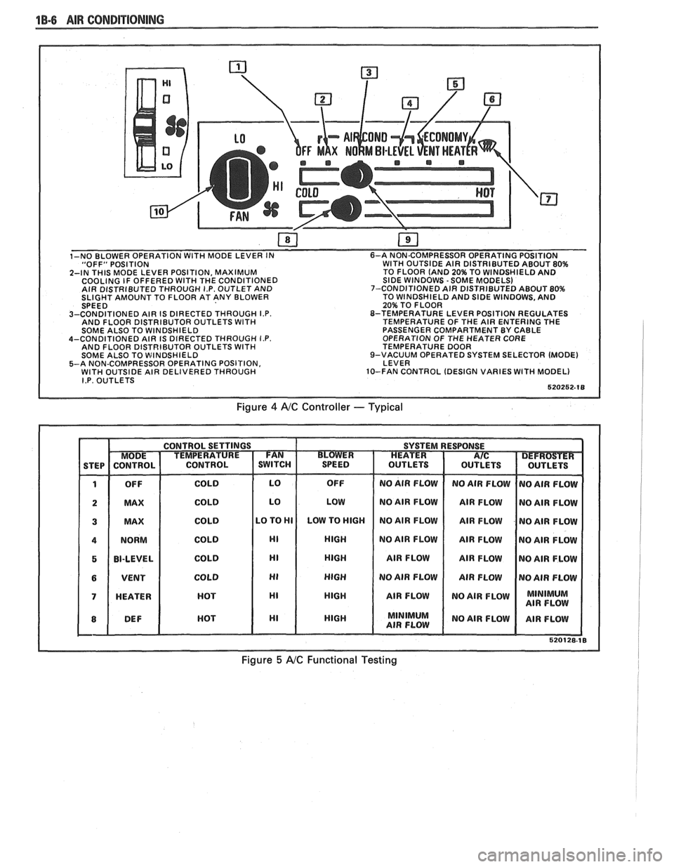
"OFF" POSITION WITH OUTSIDE AIR DISTRIBUTED ABOUT 80%
2-IN THIS MODE LEVER POSITION, MAXIMUM TO
FLOOR (AND 20% TO WINDSHIELD AND
COOLING IF OFFERED WITH THE CONDITIONED SIDE WINDOWS -SOME MODELS)
AIR DISTRIBUTED THROUGH I.P. OUTLET AND 7-CONDITIONED
AIR DISTRIBUTED ABOUT 80% SLIGHT AMOUNT TO FLOOR AT ANY BLOWER TO
WINDSHIELD AND SIDE WINDOWS, AND
20% TO FLOOR
3-CONDITIONED AIR IS DIRECTED THROUGH
I.P. 8-TEMPERATURE LEVER POSITION REGULATES
AND FLOOR DISTRIBUTOR OUTLETS WITH TEMPERATURE OF THE AIR ENTERING THE
SOME ALSO TO WINDSHIELD PASSENGER
COMPARTMENT BY CABLE
4-CONDITIONED AIR IS DIRECTED THROUGH
I.P. OPERATION OF THE HEATER CORE
AND FLOOR DISTRIBUTOR OUTLETS WITH TEMPERATURE DOOR
SOME ALSO TO WINDSHIELD 9-VACUUM
OPERATED SYSTEM SELECTOR (MODE)
5-A NON-COMPRESSOR OPERATING POSITION, LEVER
WITH OUTSIDE AIR DELIVERED THROUGH 10-FAN CONTROL
(DESIGN VARIES WITH MODEL) I.P. OUTLETS
Figure 4 AIC Controller -- Typical
Figure 5 A/C Functional Testing
Page 62 of 1825
AIR CONDITIONING 18-19
3. Push the tube into the fitting, bottoming it out.
Tighten
@ Torque nut to 15 Nam (11 lbs. ft.).
4. Dissasemble the joint.
5. Lubricate the
"0" ring with clean 525 viscosity
refrigerant oil.
6. Install the
"0" ring
on the tube. (See figure 17b)
7. Reassemble joint.
Tighten
@ Torque nut to 15 Nem (11 lbs. ft.).
8. Evacuate, charge, and leak test the system.
EXPANSlON "%BE (ORIFICE) SERVlCE
Remove or Disconnect
1. Discharge system.
2. Loosen fitting
at liquid line to evaporator inlet
pipe and remove tube carefully with needle
nosed pliers or Tool
5-26549-C or equivalent.
Install or Connect
1. Install
new orifice tube with shorter screen end
in first.
2. Install
liquid line and torque to proper
specification.
3. Evacuate and charge system.
In the event that difficulty is encountered during
the removal of a restricted or plugged expansion tube
(orifice tube), the following procedure is recom-
mended:
1. Remove
as much of any impacted residue as
possible.
2. Carefully apply heat with heat gun (hair drier,
epoxy drier or equivalent) approximately
114
inch from dimples on inlet pipe. Do not over-
heat pipe.
NOTICE: If the system has a pressure switch
near the orifice tube location, it should be
removed prior to heating the pipe to avoid dam-
age to switch.
3. While applying heat, use orifice removal tool
5-26549-C to grip the orifice tube. Use a turning
motion along with a push-pull motion to loosen
to the impacted orifice tube and remove it.
4. Swab inside of evaporator inlet pipe with R-11.
5, Add
1 oz. of 525 viscosity refrigerant oil to
system.
6. Lubricate new orifice tube and O-ring with 525'
viscosity refrigerant oil and insert into inlet
pipe. Install in proper direction (smaller screen
first).
ACCUMULATOR ASSEMBLY SERVICE
The accumulator assembly for the refrigerant
system has a service replacement which includes two
(2) O-rings (for the inlet and outlet connections). The
desiccant within the shell is NOT serviced separately
- it is part of the sealed accumulator assembly. See
REFRIGERANT OIL DISTRIBUTION for condi-
tions when the accumulator must be removed from the
vehicle to measure the amount of oil present inside the
accumulator.
The accumulator assembly should ONLY be
replaced when:
1. A physical perforation to the accumulator is
found, resulting in a leak.
2. If the system is open to air for an extended
period of time (due to a front-end collision,
removed parts, ect.). The desiccant bag will be
saturated with moisture.
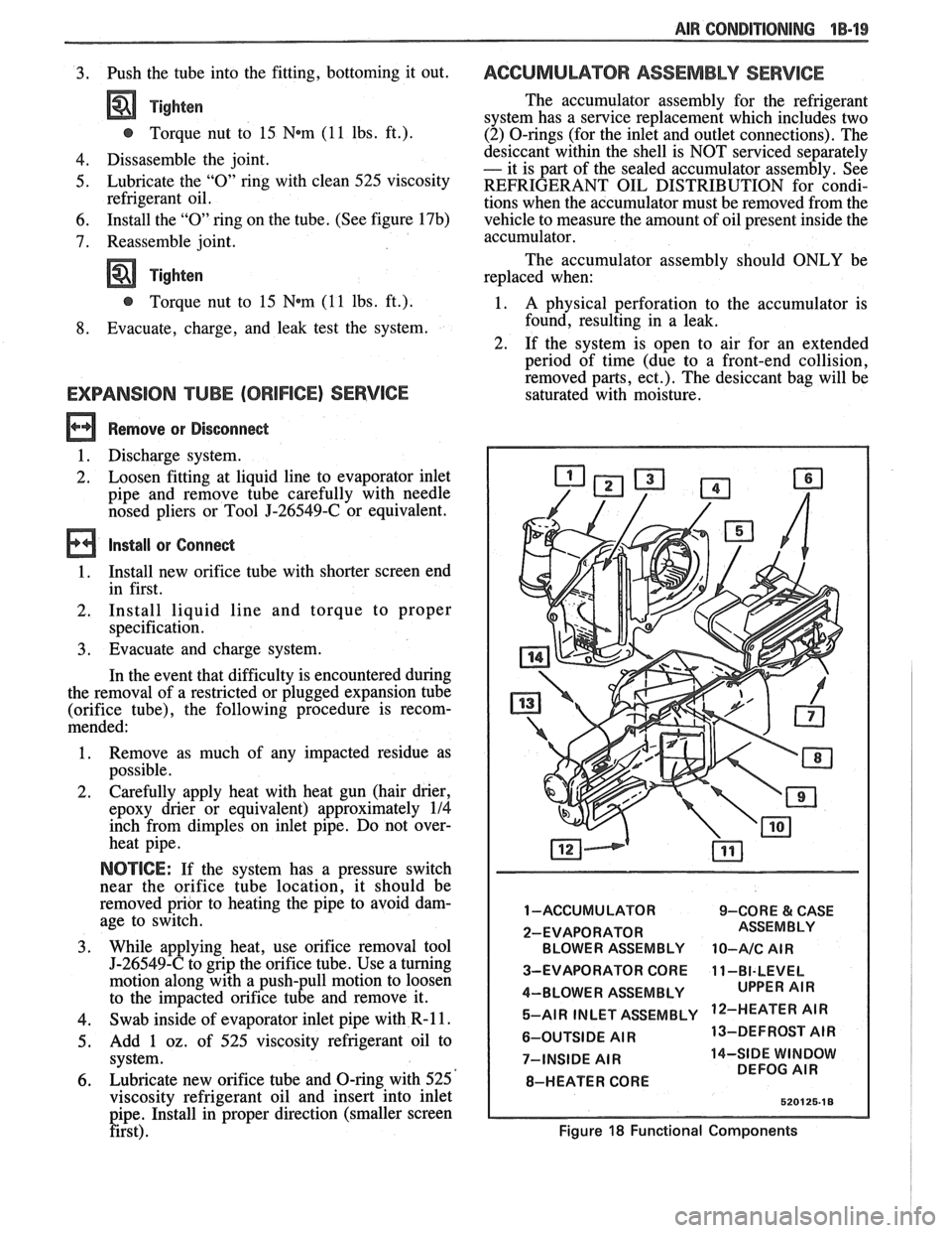
1 -ACCUMULATOR 9-CORE & CASE
2-EVAPORATOR BLOWER ASSEMBLY
10-A/C AIR
3-EVAPORATOR CORE 11-BI-LEVEL
4-BLOWER ASSEMBLY 5-AIR INLET ASSEMBLY
'IR
6-OUTSIDE AIR 13-DEFROST
AIR
7-INSIDE
AIR 14-SIDE WINDOW
DEFOG AIR
8-HEATER CORE
Figure 18 Functional Components
Page 63 of 1825
18-28 AIR CONDITIONING
DO NOT REPLACE the accumulator assembly
when:
1. Merely a dent is found in the outer shell of the
accumulator.
2. A
vehicle is involved in a collision and no phys-
ical perforation to the accumulator is found.
OM-VEHICLE SERVICE
R-"1 CHARGING CAPACITIES
The 420ml (14 fl. oz.) disposable can of R-12
refrigerant is equivalent to .399 kg (. 88 lb.).
BLOWER MOTOR
a Remove or Disconnect
1. Disconnect negative battery cable.
2. Remove motor cooling tube.
3. Disconnect electrical connections.
4. Remove blower motor attaching screws, remove
motor and case assembly.
5. Loosen retaining nut and remove blower cage
from motor shaft.
6. Inspect blower cage for broken vanes, etc.
Replace if necessary.
Install or Connect
1. Reverse removal procedure to reinstall. Replace
seals or sealant as required.
HI-BLOWER RELAY
Relay is a plug-in type with connector mounted
on top of the evaporator case.
BLOWER RESISTOR
Remove or Disconnect
1. Disconnect negative battery cable.
2. Disconnect electrical connections.
3. Remove two (2) screws, remove resistor.
Install or Connect
1. Reverse removal procedure to reinstall.
CONTROLLER, BLOWER SWITCH OR
WCUUM VALVE
Remove or Disconnect
1. Disconnect negative battery cable.
2. Remove NC control-radio console trim plate.
3. Remove three (3) NC control retaining screws.
4. Pull A/C control out and disconnect electrical
and vacuum connections and remove tempera-
ture cable.
5. Remove A/C control and replace vacuum valve
or blower switch as required.
Install or Connect
1. Reverse removal procedure to reinstall. Install
lower right screw in controller first to align con-
troller in console.
TEMPERATURE CONTROL CABLE,
VACUUM HARNESS
Remove or Disconnect
1. Remove the following hush panel(s):
a. Vacuum Harness - R.H. and L.H. hush
panel.
b. Temperature Cable
- R.H. hush panels.
Remove
controller/radio console trim plate.
Remove three (3) controller screws and pull
controller partially out of console.
Disconnect controller
end(s) of temperature
cable
andlor vacuum harness.
Disconnect component
end(s) of temperature
cable
andlor vacuum harness.
Install or Conned
1. Reverse removal procedure to reinstall. When
installing controller, install lower right screw
first to align controller location. Replace any
retaining straps, etc. removed.
2. Perform functional check of controller.
CONTROL WlRlNG HARNESS
a Remove or Disconnect
1. Disconnect negative battery cable.
2. Remove
control/radio console trim plate and
hush panels (see Section
8C).
3. Remove three (3) screws holding control in con-
sole and pull control out far enough to discon-
nect electrical and vacuum connector. Remove
controller.
4. Remove instrument panel carrier (see Section
8C).
5. Remove heater case covers (core and mode door
sides).
6. Remove two (2) interior screws and one (1)
exterior nut holding case to cowl. Pull left side
of case back to gain access to harness at cowl.
Case will still be retained by one (I) screw
behind the evaporator core
- do not attempt
complete removal of case. -
7. Loosen cowl grommet and disconnect purple
vacuum line.
Page 64 of 1825
AIR CONDITIONING 18-21
8. Disconnect blower motor
and blower resistor
electrical connection.
9. Remove hi-blower relay connector from evapo-
rator case.
10. Carefully pull
cowl grommet from cowl and pull
wiring
hmess into engine compartment.
Install or Connect
1. Reverse removal procedure to
reinstall. When
reinstalling controller, install lower right screw
first to align controller.
ACNENTILATIONIDEFROSVER DUCTS
See section 8C for removal.
HEATER CORE
Remove or Disconnect
1. Negative battery cable.
2. Drain cooling system.
3. Remove heater inlet and outlet hoses
from
heater core.
4. Remove right lower hush panel (see Section
8C).
5. Remove right
lower I.P. trim panel (see Section
8C) .
6. Remove lower right I.P. carrier to cowl screw.
7. Remove ECM attaching screws and move to the
side.
8. Remove four
(4) heater case cover screws.
Upper left screw may be reached with a long
318 ' socket extension through the I.P. openings
exposed by removal of the lower right I.P. trim
panel. Carefully lift the lower right corner of the
I.P. to align socket extension.
9. Remove heater case cover.
10. Remove core support plate
and baffle screws.
- -
11. Remove
heater core, support plate and baffle
from case.
Install or Conned
1. Reverse removal procedure to reinstall. Restore
all seals
and/or sealant disturbed during removal
procedure.
2. Refill cooling system and check for leaks.
LOWER (FLOOR) )-IEA"FEB$OU"fET
Remove or Disconnect
1. Console. (See Section 8C.)
2. L.H. and R.H. hush panels.
3. Two (2) floor outlet retaining screws.
4. Floor outlet from core case.
lnstall or Connect
1. Floor outlet to core case.
2. Two (2) floor outlet retaining screws.
3. L.H. and R.H. hush panels.
4. Console.
HEATER MODULE (CASE)
Remove or Disconnect
1. Disconnect negative battery cable.
2. Drain cooling system.
3. Remove hush panels and instrument panel car-
rier (see Section
8C).
4. Remove lower heater outlets.
5. Disconnect control cables and vacuum hoses at
module and controller.
6. Remove heater core.
7. Remove two (2) interior screws and one (I)
exterior nut holding case to cowl.
8. Remove evaporator core.
9. Remove screw holding case to cowl from engine
compartment side.
10. Remove case (module).
11. Transfer usable parts to new case (module).
lnstall or Conned
1. Reverse removal procedure to reinstall.
2. Refill coolant system.
3. Recharge
A/C system.
4. Inspect A/C and cooling system for leaks.
NC PRESSURE CYCLING SWITCH
Do not discharge A/C system. Pressure cycling
switch is mounted on
a Schrader-type valve.
Remove or Disconnect
1. Disconnect switch electrical connection.
2. Remove switch.
Install or Connect
1. Reverse removal procedure to reinstall. Tighten
switch to
4-5.5 N*m (35-49 in. lb.).
Ale CONTROL VACUUM TANK
Remove or Disconnect
1 . Disconnect vacuum hoses.
2. Remove vacuum
tank attaching screws, remove
tank.
lndall or Connect
1. Reverse removal procedure to
reinstall.