1988 PONTIAC FIERO air suspension
[x] Cancel search: air suspensionPage 2 of 1825
1988
SER
This manual applies to the 1988 Pontiac Firebird Models.
It contains the latest product information available at the
time of publication approval. lnformation pertaining to
the operation of the vehicle is contained in the Owner's
Manual which accompanies each vehicle. The right is
reserved to make changes at any time without notice.
Any references to brand names in this manual is intended
merely as an example of the types of
lubricant% tools,
materials, etc, recommended for use in servicing 1988
Pontiac Models. In all cases, an equivalent may be used.
PONTIAC DIVISION
GENERAL
MOTORS CORPORATION
PONTIAC, MICHIGAN 48053
1987 General Motors Corp. All Rights Reserved.
No part of this publication may be reproduced, stored in any
retrieval system or transmitted in any form or by any means,
including but not limited to electronic, mechanical,
photocopying, recording or otherwise, without the prior written
permission of General Motors Corp. This includes all text,
illustrations, tables and charts.
S-881 OF 9-87 Printed in Canada
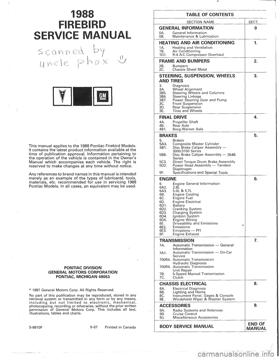
TABLE OF CONTENTS
SECTION NAME
GENERAL INFORMATION
OA. General lnformation
OB. Maintenance & Lubrication
1 SECT.
HEATING AND AIR CONDITIONING
1A. Heating and Ventilation
1 B. Air Conditioning
1D1. R-4 AIC Com~ressor Overhaul
FRAME AND BUMPERS
2B. Bumpers 2C. Chassis Sheet Metal
STEERING, SUSPENSION, WHEELS
AND TIRES
3. Diagnosis
3A. Wheel Alignment
3B5. Steering Wheels and Columns 3B6. Steering Linkage 3B7. Power Steering Gear and Pump
3C. Front Suspension
3D. Rear Suspension
3E. Tires and Wheels
FINAL DRIVE
4A. Propeller Shaft
4B. Rear Axle
4B1. Bora-Warner Axle
BRAKES 5. Brakes 5A3. Comoosite Master Cvlinder 5B1. Disc r rake Caliper ~ssembly - 300013100 Series 5B6. Disc Brake Caliper Assembly - 3548
Series
5C3. Direct Torque Drum Brake Assembly 5D2. Power Head Assembly - Tandem Diaohraam 5F. ~~ecifications and Special Tools
ENGINE 6. Engine General lnformation 6A2. 2.8L 6A3. 5.OL & 5.7L 6B. Engine Cooling
6C. En~ine Fuel
6D. ~ngine Electrical 6D1. Battery 6D2. Cranking System 6D3. Charging System 6D4. Ignition System 6D5. Engine Wiring
6E. Driveabilitv and Emissions
6E2. ~missions' 6E3. Emissions - PFI
6F. Engine Exhaust
TRANSMISSION 7A. Automatic Transmission - General
lnformation
7A1. Automatic Transmission - On-Car
Service
700R4. Automatic Transmission Hydraulic Diagnosis
700R4. Automatic Transmission Unit Repair
76. 5-Speed Manual Transmission
7C. Clutch
CHASSIS ELECTRICAL 8A. Electrical Diagnosis
8B. Lighting and Horns
8C. Instrument
Panel, Gages
& Console
8E. Windshield Wiper &Washer System
ACCESSORIES 9A. Radio Systems and Antennas 9B. Cruise Control 9G. Miscellaneous Accessories
I BODY SERVICE MANUAL END
OF
MANUAL
Page 18 of 1825
MAINTENANCE AND LUBRICATION OB-1
SECTION OB
NTENANCE AND LUBR
CONTENTS
Maintenance Schedule, Gasoline .............................................. OB-l
Maintenance Schedules I and 11 .............................................. OB-2
Owner Inspections
......................................................... OB-3
Recommended Fluids and Lubricants ......................................... OB-6
PASSENGER CAR MAINTENANCE SCHEDULE
VEHICLES
WITH GASOLINE ENGINE
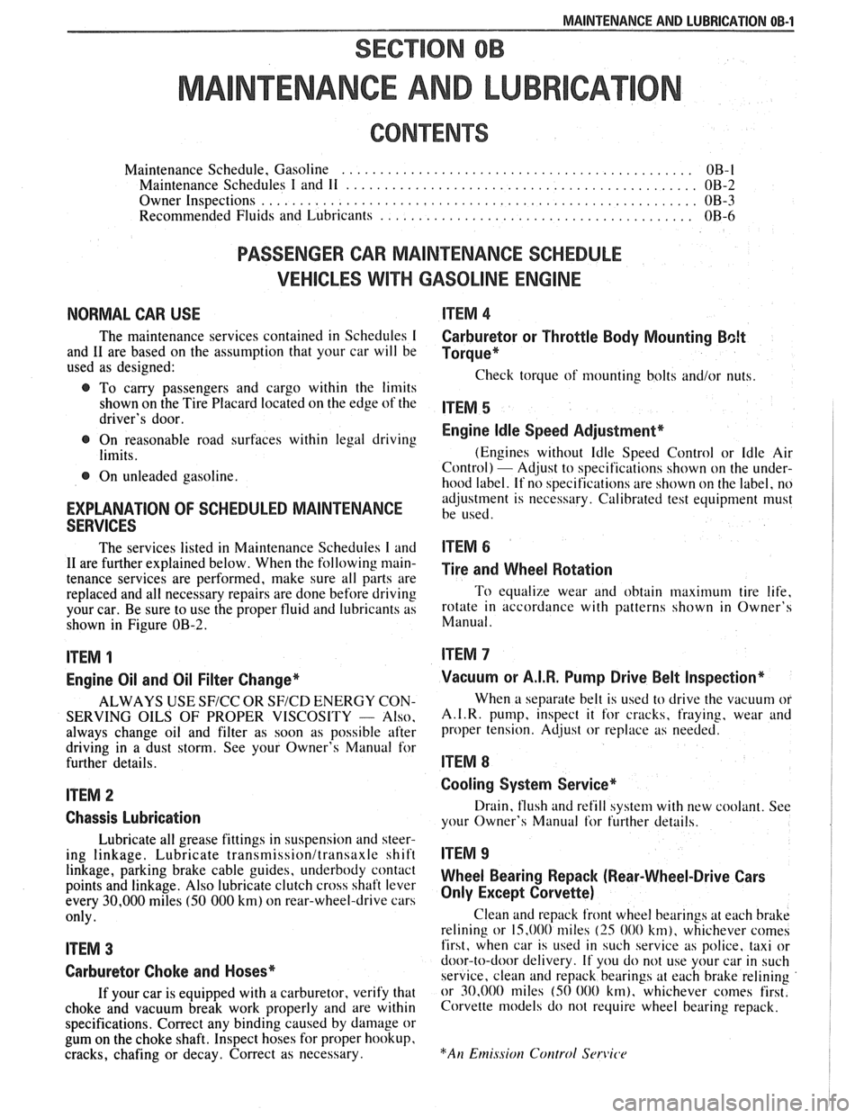
NORMAL CAR USE ITEM 4
The maintenance services contained in Schedules I Carburetor or Throttle Body Mounting Bolt
and 11 are based on the assumption that your car will be Torque* used as designed:
Check torque of mounting bolts and/or nuts. @ To carry passengers and cargo within the limits
shown on the Tire Placard located on the edge of the ITEM 5 driver's door.
@ On reasonable road surfaces within legal driving Engine Idle Speed Adjustment*
limits. (Engines
without Idle Speed Control or Idle Air
Control) - Adjust to specifications shown on the under- @ On unleaded gasoline.
hood label. If no specifications are shown on the label, no
adjustment is necessary. Calibrated test equipment must
EXPLANATION OF SCHEDULED MAINTENANCE be used. SERVICES
The services listed in Maintenance Scheduies I and ITEM 6
11 are further explained below. When the following main- ~i~~ and wheel aotation tenance services are performed, make sure all parts are
replaced and all necessary repairs are done before driving To equalize wear and obtain maximum tire life,
your car. Be sure to use the proper fluid and lubricants as rotate in accordance with patterns shown in Owner's
shown in Figure OB-2. Manual.
ITEM 1
Engine Oil and Oil Filter Change*
ALWAYS USE SFICC OR SF/CD ENERGY CON-
SERVING OILS OF PROPER VISCOSITY
- Also.
always change oil and filter as soon as possible after
driving in a dust storm. See your Owner's Manual for
further details.
ITEM 2
Chassis Lubrication
Lubricate all grease fittings in suspension and steer-
ing linkage. Lubricate
transmissionltransaxle shift
linkage, parking brake cable guides, underbody contact
points and linkage. Also lubricate clutch cross shaft lever
every
30,000 miles (50 000 km) on rear-wheel-drive cars
only.
ITEM 3
Carburetor Choke and Hoses*
If your car is equipped with a carburetor, verify that
choke and vacuum break work properly and are within
specifications. Correct any binding caused by damage or
gum on the choke shaft. Inspect hoses for proper hookup,
cracks, chafing or decay. Correct as necessary.
Vacuum or A.I.R. Pump Drive Belt Inspection*
When a separate belt is used to drive the vacuum or
A.I.R.
pump, inspect it for cracks, fraying, wear and
proper tension. Adjust or replace as needed.
ITEM 8
Cooling System Service*
Drain, flush and refill system with new coolant. See
your Owner's Manual
for further details.
ITEM 9
Wheel Bearing Repack (Rear-Wheel-Drive Cars
Only Except Corvette)
Clean and repack front wheel bearings at each brake
relining or 15,000 miles
(25 000 km), whichever comes
first, when car is used in such service as police, taxi or
door-to-door delivery. If you do not use your car in such
service, clean and repack bearings at each brake relining
or 30,000 miles
(50 000 km), whichever comes first.
Corvette models do not require wheel bearing repack.
Page 21 of 1825
OB-4 MAINTENANCE AND LUBRICATION
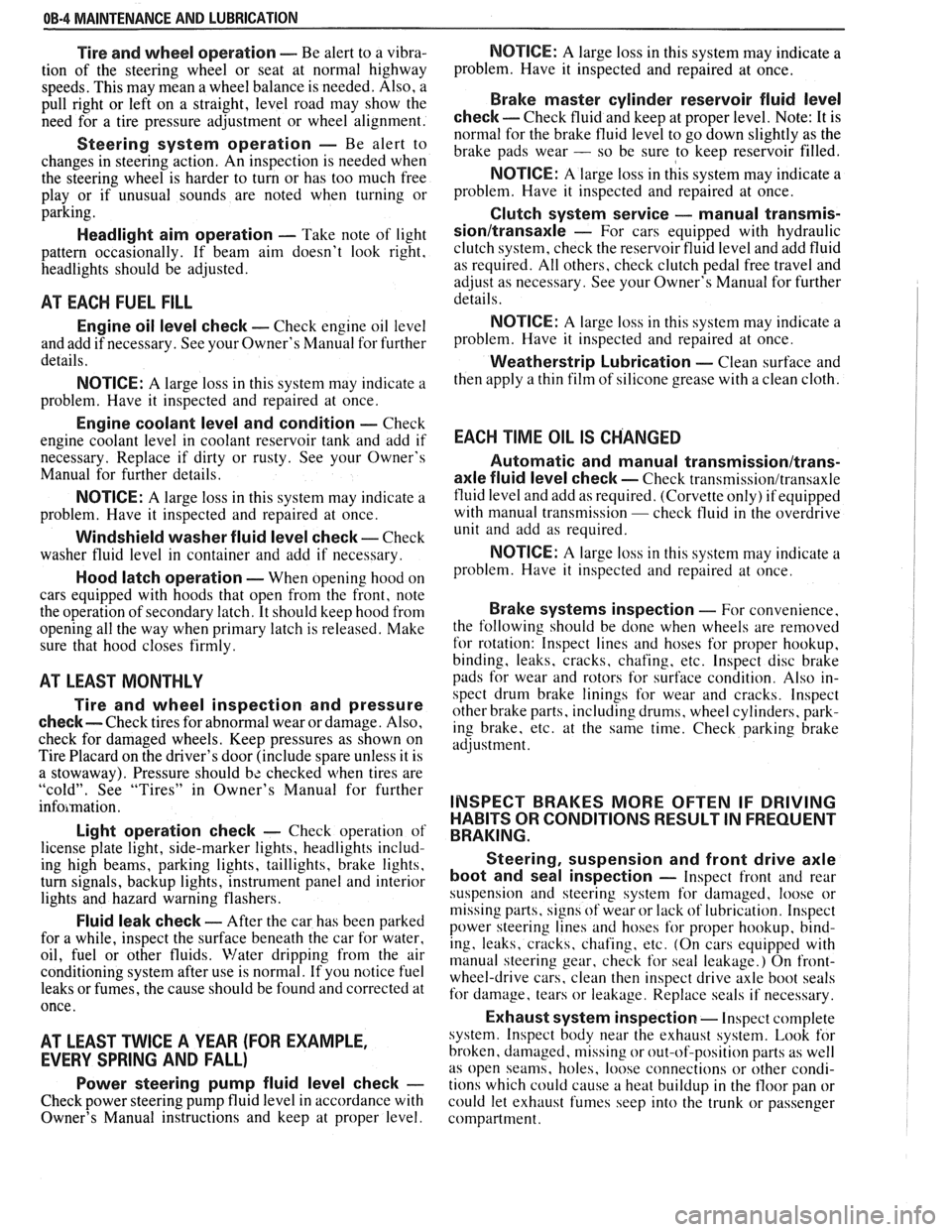
Tire and wheel operation - Be alert to a vibra-
tion of the steering wheel or seat at normal highway
speeds. This may mean a wheel balance is needed. Also, a
pull right or left on a straight, level road may show the
need for
a tire pressure adjustment or wheel alignment.
Steering system operation - Be alert to
changes in steering action. An inspection is needed when
the steering wheel is harder to turn or has too much free
play or if unusual sounds are noted when turning or
parking.
Headlight aim operation - Take note of light
pattern occasionally. If beam aim doesn't look right,
headlights should be adjusted.
AT EACH FUEL FILL
Engine oil level check - Check engine oil level
and add if necessary. See your Owner's
Manual for further
details.
NOTICE: A large loss in this system may indicate a
problem. Have it inspected and repaired at once.
Engine coolant level and condition - Check
engine coolant level in coolant reservoir tank and add if
necessary. Replace if dirty or rusty. See your Owner's
Manual for further details.
NOTICE: A large loss in this system may indicate a
problem. Have it inspected and repaired at once.
Windshield washer fluid level check -- Check
washer fluid level in container and add if necessary.
Hood latch operation - When opening hood on
cars equipped with hoods that open from the front, note
the operation of secondary latch. It should keep hood from
opening all the way when primary latch is released. Make
sure that hood closes firmly.
AT LEAST MONTI-ILY
Tire and wheel inspection and pressure
check--
Check tires for abnormal wear or damage. Also,
check for damaged wheels. Keep pressures as shown on
Tire Placard on the driver's door (include spare unless it is
a stowaway). Pressure should b\: checked when tires are
"cold". See "Tires" in Owner's Manual for further
infomation.
Light operation check - Check operation of
license plate light, side-marker lights, headlights includ-
ing high beams, parking lights, taillights, brake lights.
turn signals, backup lights, instrument panel and interior
lights and hazard warning flashers.
Fluid leak check - After the car has been parked
for a while, inspect the surface beneath the car for water,
oil, fuel or other fluids. Water dripping from the air
conditioning system after use is normal. If you notice fuel
leaks or fumes, the cause should be found and corrected at
once.
AT LEAST TWICE A YEAR (FOR EXAMPLE,
EVERY SPRING AND FALL)
Power steering pump fluid level check --
Check power steering pump fluid level in accordance with
Owner's Manual instructions and keep at proper level.
NOTICE: A large loss in this system may indicate a
problem. Have it inspected and repaired at once.
Brake master cylinder reservoir fluid level
check ---- Check fluid and keep at proper level. Note: It is
normal for the brake fluid level to go down slightly as the
brake pads wear
- so be sure to keep reservoir filled.
NOTICE: A large loss in this system may indicate a
problem. Have
it inspected and repaired at once.
Clutch system service --- manual transmis-
sionltransaxle --- For cars equipped with hydraulic
clutch system, check the reservoir fluid level and add fluid
as required. All others, check clutch pedal free travel and
adjust as necessary. See your Owner's Manual for further
details.
~
NOTICE: A large loss in this system may indicate a
problem. Have it inspected and repaired at once.
Weatherstrip Lubrication - Clean surface and
then apply a thin film of silicone grease with a clean cloth.
EACH TIME OIL IS CHANGED
Automatic and manual transmissionltrans-
axle fluid level check - Check transmission/transaxle
fluid level and add as required. (Corvette only) if equipped
with manual transmission
- check fluid in the overdrive
unit and add as required.
NOTICE: A large loss in this system may indicate a
problem. Have
it inspected and repaired at once.
Brake systems inspection - For convenience,
the following should be done when wheels are removed
for rotation: Inspect lines and hoses for proper hookup,
binding, leaks, cracks, chafing, etc. Inspect disc brake
pads for wear and rotors for surface condition. Also in-
spect drum brake linings for wear and cracks. Inspect
other brake parts, including drums, wheel cylinders, park-
ing brake, etc. at the same time. Check parking brake
adjustment.
INSPECT BRAKES MORE OFTEN IF DRIVING
HABITS OR CONDITIONS RESULT IN FREQUENT
BRAKING.
Steering, suspension and front drive axle
boot and seal inspection
- Inspect front and rear
suspension and steering system for damaged, loose or
missing parts, signs of wear or lack of lubrication. Inspect
power steering lines and hoses for proper hookup, bind-
ing, leaks, cracks, chafing, etc. (On cars equipped with
manual steering gear, check for seal leakage.) On
front-
wheel-drive cars, clean then inspect drive axle boot seals
for damage, tears or leakage. Replace seals if necessary.
Exhaust system inspection - Inspect complete
system. Inspect body near the exhaust system. Look for
broken, damaged, missing or out-of-position parts as well
as open seams, holes, loose connections or other condi-
tions which could cause a heat buildup in the tloor pan or
could let exhaust fumes seep into the trunk or passenger
compartment.
Page 128 of 1825
STEERING, SUSPENSION, VIBES AND WHEELS DIAGNOSIS 3-3
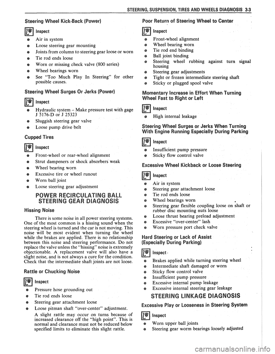
Steering Wheel Kick-Back (Power)
Inspect
e Air in system
e Loose steering gear mounting
e Joints from column to steering gear loose or worn
e Tie rod ends loose
Worn or missing check valve
(800 series)
e Wheel bearings worn
e See "Too Much Play In Steering" for other
possible causes.
Steering Wheel Surges Or Jerks (Power)
Inspect
Hydraulic system - Make pressure test with gage
J 5176-D or
J 25323
e Sluggish steering gear valve
Loose pump drive belt
Cupped Tires
Inspect
Front-wheel or rear-wheel alignment
e Strut dampeners or shock absorbers weak
e Wheel bearing worn
e Excessive tire or wheel runout
e Worn ball joint
a Loose steering gear adjustment
POWER RECIRCULATING BALL
SEERING GEAR DIAGNOSIS
Hissing Noise
There is some noise in all power steering systems.
One of the most common is a hissing sound when the
steering wheel is turned and the car is not moving. This
noise will be most evident when turning the wheel
while the brakes are applied. There is no relationship
between this noise and steering performance. Do not
replace the valve unless the "hissing" noise is extremely
objectionable. A replacement valve will also have a
slight noise, and is not always a cure for the condition.
Check that the intermediate shaft joints are not loose.
Rattle or Chucking Noise
Inspect -
Pressure hose grounding out
e Tie rod ends loose
e Steering gear attachment loose
a Loose pitman shaft "over-center" adjustment.
A slight rattle may occur on turns because of
increased clearance off the "high point". This is
normal and clearance must not be reduced below
specified limits to eliminate this slight rattle.
Poor Return of Steering Wheel to Center
Front-wheel alignment
Wheel bearing worn
Tie rod end binding
Ball joint binding
Steering wheel rubbing against turn signal
housing
Steering gear adjustments
Tight or frozen intermediate steering shaft
Sticky or plugged spool valve
Momentary Increase in Effort Whsn Turning
Wheel Fast to Right or Left
Inspect
High internal leakage
Steering Wheel Surges or Jerks When Turning
With
Engine Running Especially During Parking
ln8pe~t
e Insufficient pump pressure
Sticky flow control valve
Excessive Wheel Kickback or Loose Steering
Air in system
Steering gear attachment loose
Tie rod ends loose
Wheel bearings worn
Steering gear flexible coupling loose on shaft or
rubber disc mounting nuts loose
Loose thrust bearing preload adjustment
Excessive "over-center" lash
Worn pressure port check valve
Hard Steering or Lack of Assist
(Especially During Parking)
-
Brakes applied while turning steering wheel
Intermediate shaft damaged or worn
e Sticky flow control valve
Insufficient pump pressure
Excessive internal pump leakage
Excessive internal steering gear leakage
STEERING LINKAGE DIAGNOSIS
Excessive Play or Looseness in Steering Systern
inspect
r, Worn upper ball joints
e Steering gear worm bearings loosely adjusted
Page 129 of 1825
3.4 STEERING, SUSPENSION, TIRES AND WHEELS DIAGNOSIS
e Excessive pitman shaft to ball nut lash in steering
gear
e Worn intermediate rod or tie rod sockets
Excessive Looseness in Tie Rod or Intermediate
Rod Pivots, or Excessive Vertical Lash in
Idler
Support
Inspect -
e Seal damage and leakage resulting in loss of
lubricant, corrosion and excessive wear
Hard Steering
0 Inspect
e Tight or frozen intermediate rod, tie rod or idler
socket
e Steering gear adjusted too tight
POWER STEERING PUMP DIAGNOSIS
Foarning, Milky Power Steering Fluid, Low Fluid
Level, and Possible Low Pressure
This can be caused by air in the fluid, and loss of
fluid due to internal pump leakage causing overflow.
Check for leak and correct. Bleed the system.
Extremely cold temperatures will cause air bubbles in
the system if the fluid level is low. If the fluid level is
correct and pump still foams, remove pump from car
and separate reservoir from housing. Check soft plug
and housing for cracks. If housing is cracked, replace
housing.
Low Pressure Due to Steering Pump
Inspect
e Flow control valve stuck or inoperative
e Pressure plate not flat against cam ring
e Extreme wear of cam ring
e Scored pressure plate, thrust plate or rotor
e Vanes sticking in rotor slots
Q Cracked or broken thrust or pressure plate
e High internal leakage
Low Pressure Due To Steering Gear
Inspect
e Scored housing bore
Q Leakage at valve rings or seals
Growling Noise in Steering Pump
Inspect
e Excessive back pressure in hoses or steering gear
caused by restriction
e Scored pressure plates, thrust plate or rotor
e Worn cam ring
Groaning Noise in Steering Pump
Inspect
e Air in the fluid
Low fluid level
Q Pump mounting loose
Rattling Noise in Steering Pump
Inspect - -
e Vanes sticking in rotor slots
o Vane improperly installed
o Damaged ball bearing
Swishing Noise in Steering Pump
inspect
e Damaged flow control valve
Whining Noise in Steering Pump
Inspect
Q Pump shaft bearing scored
e Scored pressure plates and vanes
STEERING COLUMN DIAGNOSIS
LOCK SYSTEM
Will Not Unlock
Inspect
o Shear flange on sector shaft collapsed
Q Damaged lock bolt
e Damaged lock cylinder
o Damaged housing
e Damaged sector
e Damaged rack
e Damaged park lock cable
Will Not Lock
Inspect
Lock bolt spring broken or worn
Damaged sector
Damaged lock cylinder
Burr on lock bolt
Damaged housing
Improper shift linkage adjustment
Damaged rack
Interference between bowl and rack coupling
Ignition switch stuck
Actuator rod restricted
Sector installed incorrectly
Park lock cable damaged
Page 132 of 1825
STEERING, SUSPENSION, TIRES AND WHEELS DIAGNOSIS 3-7
e To determine if turn signal switch is inoperative,
substitute new turn signal switch into circuit and
operate switch by hand.
If the car's lights operate
normally, turn signal switch is inoperative.
Front Or Rear Turn Signal Lights Not Flashing
Inspect
s Burned-out or damaged turn signal bulb
e High resistance conection to ground at bulb
socket
s Loose chassis-to-column connector. Disconnect
column-to-chassis connector and connect new
turn signal switch into system and operate switch
by hand.
A. If turn signal lights are now on and flashing,
turn signal switch is inoperative.
B. If car lights do not operate, refer to Section
8A
for electrical diagnosis.
Turn Indicator Panel Lights
Inspect
Burned out bulbs or opens, grounds in the wiring
harness from the front turn signal bulb socket to the
indicator lights. Refer to Section
8A for electrical
diagnosis.
Stop Light Mot On When Turn Indicated
Inspect
s Loose column-to-chassis connection
e Disconnect the column-to-chassis connector and
connect the new turn signal switch into the
system and operate the switch by hand.
A. If the brake lights work when the switch is
in the turn position, the turn signal switch
is inoperative.
B. If the brake lights do not work, refer to Section
8A for electrical diagnosis.
Turn Signal Lights Flash Very Slowly
e Loose chassis-to-column connection
a Disconnect the column-to-chassis connector and
connect a new turn signal switch into the system
and operate the switch by hand.
A. If the lights flash at a normal rate, the turn
signal switch is inoperative.
B. If the Lights still flash very slowly, refer to
Section
8A for electrical diagnosis.
Hazard Signal Lights Will Not Flash - Turn
Signal Functions Normally
~"SPBC~
a Blown fuse
Inoperative hazard warning flasher
e Loose chassis-to-column connection
s Disconnect the column-to-chassis connector and
connect a new turn signal switch into the system,
then press in the hazard warning button and
watch the hazard warning lights.
A. If the lights now work normally, the turn
signal switch is inoperative.
B. If the lights do not flash, check the wiring
harness. Refer to Section
8A for electrical
diagnosis.
IGNITION SWITCH
Electrical System Will Not Function
Damaged ign~rion switch
e Ignition switch not adjusted properly
e Loose connector at the ignition switch
Switch Will Not Turn
Inspect
Damaged ignition switch
Switch Cannot Be Set Correctly
Inspect
Switch actuator rod deformed
e Sector to rack engaged in wrong tooth
KEY REMINDER
Figs. 1 through 11 ,
Weminder Continues To Operate With Key Out,
But Stops When Driver's Door Is Closed
e Chips, foreign material in lock cylinder bore
Sticky lock cylinder actuator tip
Damaged or broken reminder switch
Reminder Does Not Sound With Key Fully
Inserted In Lock Cylinder And The Driver's Door
Open
Inspect
1. Power not available to reminder. Refer to Sec-
tion
8A for electrical diagnosis.
2. Open in chassis wiring. Check by separating
chassis-to-column connector. Connect terminals
"E" and "F" female contacts on the chassis
connector (a bent paper clip will work). If the
reminder sounds, repair chassis wiring. If the
reminder does not sound, go to Step
A.
A. Connect a continuity meter (light) to the
male
"E" and "F" column connector
contacts. Push the key all the way into the
lock cylinder. If the light is on when the key
Page 135 of 1825

3-10 STEERING, SUSPENSION, TIRES AND WHEELS DIAGNOSIS
Reminder Keeps Operating With Key In Lock
Cylinder, Driver's Door Open Or Closed; Ceases
When Key Is Removed
Inspect
s Door jamb switch on driver's side misadjusted or
inoperative.
e Wire from signal switch to door jamb switch
shorted.
A. This condition indicates the lock cylinder or
the reminder switch is at fault. To verify,
check for continuity at the
"E" and "F"
male column connector contacts, with the
key removed from the lock cylinder. If
continuity exists, the fault is in the column.
B. Insert the key into the lock, then turn the
lock toward the "Start" position. If the
reminder stops when the key is in the
"Run" position or when it is turned past
"Run" toward "Start," the problem is a
sticky lock cylinder actuator.
COLUMN-MOUNTED DIMMER SWITCH
No "Low" or "High" Beam
Inspect
e Loose connector at dimmer switch
e Improper adjustment
e Internally damaged or worn switch. Check the
continuity on the switch at the It. green and at the
tan switch terminals by pushing in the plunger all
the way.
A click should be heard. If there is no
continuity, replace the dimmer switch. If there is
continuity, refer
to'section 8A for electricaldiag-
nosis.
PIVOT AND SWITCH ASSEMBLY
Switch Inoperative: No "Low," "High" and/or
"Wash"
e Loose body-to-switch connector
a Broken or damaged switch
Internally damaged or worn switch. Connect a
new switch without removing the old one. If the
system functions, replace the switch. If the
system doesn't function, refer to Section
8A for
electrical diagnosis.
STEERING GEAR AND PUMP LEAKS
General Procedure
Inspect
s Overfilled reservoir
s Fluid aeration and overflow
e , Hose connections
Verify exact point of leakage Example:
Torsion bar, stub shaft and
adjuster seals are close together; the exact
spot where the system is leaking may not be
clear.
Example: The point from which the fluid is
dripping is not necessarily the point where
the system is leaking; fluid overflowing from
the reservoir, for instance.
e When service is required:
A. Clean leakage area upon disassembly.
B. Replace leaking seal.
C. Check component sealing surfaces for
damage.
D. Reset bolt torque to specifications, where
required.
Some complaints about the power steering system
may be reported as:
A. Fluid leakage on garage floor
B. Fluid leaks visible on steering gear or pump
C. Growling noise, especially when parking or
when engine is cold
D. Loss of power steering when parking
E. Heavy steering effort
When troubleshooting these kinds of complaints,
check for an external leak in the power steering system.
For further diagnosis of leaks, refer to External
Leakage Check in this section.
External Leakage Check
Fig. 12
The purpose of this procedure is to pinpoint the
location of the leak.
In some cases, the leak can easily be located. But,
seepage-type leaks may be more difficult to isolate. To
locate seepage leaks, use the following method.
1. With the engine off, wipe dry the complete power
steering system.
2. Check the fluid level in the pump's reservoir. Add
fluid if necessary.
3. Start the engine, then turn the steering wheel
from stop to stop several times. Do not hold it at
a stop for any length of time, as this can damage
the power steering pump. It is easier if someone
else operates the steering wheel while you search
for the seepage.
4. Find the exact area of the leak and repair leak.
SEAL REPLACEMENT
RECOMMENDATIONS
Lip seals, which seal rotating shafts, require
special treatment. This type of seal is used on the
steering gear and on the drive shaft of the pump. When
there is a leak in one of these areas, always replace the
seal(s), after inspecting and thoroughly cleaning the
sealing surfaces. Replace the shaft only if very severe
pitting is found. If the corrosion in the lip seal contact
zone is slight, clean the surface of the shaft with crocus
cloth. Replace the shaft only if the leakage cannot be
stopped by first smoothing with crocus cloth.
Page 137 of 1825
3-1 2 STEERING, SUSPENSION, TIRES AND WHEELS DIAGNOSIS
POWER STEERlNG SYSTEM "TEST
PROCEDURE
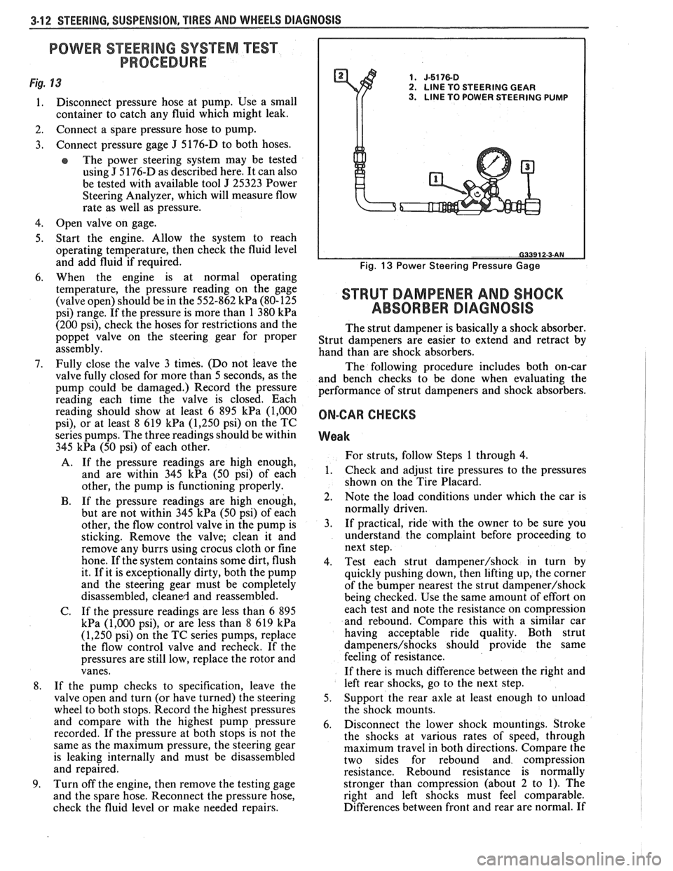
Fig. 13 1. J-5176-D 2. LlNE TO STEERING GEAR
1. Disconnect pressure hose at pump. Use a small 3. LINE TO POWER STEERING PUMP
container to catch any fluid which might leak.
2. Connect a spare pressure hose to pump.
3. Connect pressure gage
J 5176-D
to both hoses.
e The power steering system may be tested
using
J 5 176-D as described here. It can also
be tested with available tool
J 25323 Power
Steering Analyzer, which will measure flow
rate as well as pressure.
4. Open valve on gage.
5. Start the engine. Allow the system to reach
operating temperature, then check the fluid level
and add fluid if required.
6. When the engine is at normal operating
temperature, the pressure reading on the gage
(valve open) should be in the 552-862
kPa (80-125
psi) range. If the pressure is more than 1 380
kPa
(200 psi), check the hoses for restrictions and the
poppet valve on the steering gear for proper
assembly.
7. Fully close the valve 3 times. (Do not leave the
valve fully closed for more than 5 seconds, as the
pump could be damaged.) Record the pressure
reading each time the valve is closed. Each
reading should show at least 6 895
kPa (1,000
psi), or at least 8 619 kPa (1,250 psi) on the TC
series pumps. The three readings should be within
345
kPa (50 psi) of each other.
A. If the pressure readings are high enough,
and are within 345
kPa (50 psi) of each
other, the pump is functioning properly.
B. If the pressure readings are high enough,
but are not within 345
kPa (50 psi) of each
other, the flow control valve in the pump is
sticking. Remove the valve; clean it and
remove any burrs using crocus cloth or fine
hone. If the system contains some dirt, flush
it. If it is exceptionally dirty, both the pump
and the steering gear must be completely
disassembled, cleaned and reassembled.
C. If the pressure readings are less than
6 895
kPa (1,000 psi), or are less than 8 619 kPa
(1,250 psi) on the TC series pumps, replace
the flow control valve and recheck. If the
pressures are still low, replace the rotor and
vanes.
8. If the pump checks to specification, leave the
valve open and turn (or have turned) the steering
wheel to both stops. Record the highest pressures
and compare with the highest pump pressure
recorded. If the pressure at both stops is not the
same as the maximum pressure, the steering gear
is leaking internally and must be disassembled
and repaired.
9. Turn off the engine, then remove the testing gage
and the spare hose. Reconnect the pressure hose,
check the fluid level or make needed repairs.
Fig. 13 Power Steering Pressure Gage
STRUT DAMPENER AND SHOCK
ABSORBER DIAGNOSIS
The strut dampener is basically a shock absorber.
Strut dampeners are easier to extend and retract by
hand than are shock absorbers.
The following procedure includes both on-car
and bench checks to be done when evaluating the
performance of strut dampeners and shock absorbers.
ON-CAR CHECKS
Weak
For struts, follow Steps 1 through 4.
1. Check
and adjust tire pressures to the pressures
shown on the Tire Placard.
2. Note the load conditions under which the car is
normally driven.
3. If practical, ride with the owner to be sure you
understand the complaint before proceeding to
next step.
4. Test each strut
dampener/shock in turn by
quickly pushing down, then lifting up, the corner
of the bumper nearest the strut
dampener/shock
being checked. Use the same amount of effort on
each test and note the resistance on compression
and rebound. Compare this with a similar car
having acceptable ride quality. Both strut
dampeners/shocks should provide the same
feeling of resistance.
If there is much difference between the right and
left rear shocks, go to the next step.
5. Support the rear axle at least enough to unload
the shock mounts.
6. Disconnect the lower shock mountings. Stroke
the shocks at various rates of speed, through
maximum travel in both directions. Compare the
two sides for rebound and compression
resistance. Rebound resistance is normally
stronger than compression (about 2 to 1). The
right and left shocks must feel comparable.
Differences between front and rear are normal. If