1988 PONTIAC FIERO tow
[x] Cancel search: towPage 6 of 1825
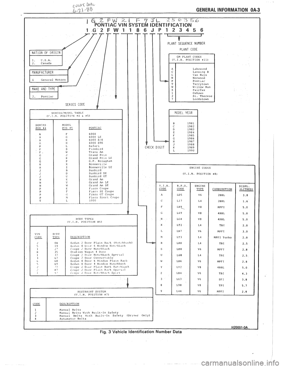
GENERAL INFORMATION OA-3
PLANT CODE
GM PLANT CODES LV.1.N. POSITION $11)
Lakrwood Lanslnq B
Norwood Pontlac Tarrytown W1:low Run
St. Therese
Lordstown
6000
SIE 6000 STE
Trans
Am Grand Prlx Grand Prlx LE
G.P. Brougham
Bonnevlile Bonnevll le LE
(V.I.N. POSITION $8) Sunblrd GT
Grand Am Grand Am LE Gr~nd Am SE
CARBURETION
I
MPFI Turbo
Sed,in 7 D~,i,r Plaln Lia~.k lIl.~t~'l~li.~ck~ Seci.in 4 Utnir 6 \$lndi,w Nott'I~L,.~ck c'
Manual Belts Manudi Belts Wlth Bullt-In Sdfrty blaiiual Belts Vltli Bullt-In Safety (Drlvrr Only)
Fig. 3 Vehicle Identification Number Data
Page 19 of 1825
OB-2 MAINTENANCE AND LUBRICATION
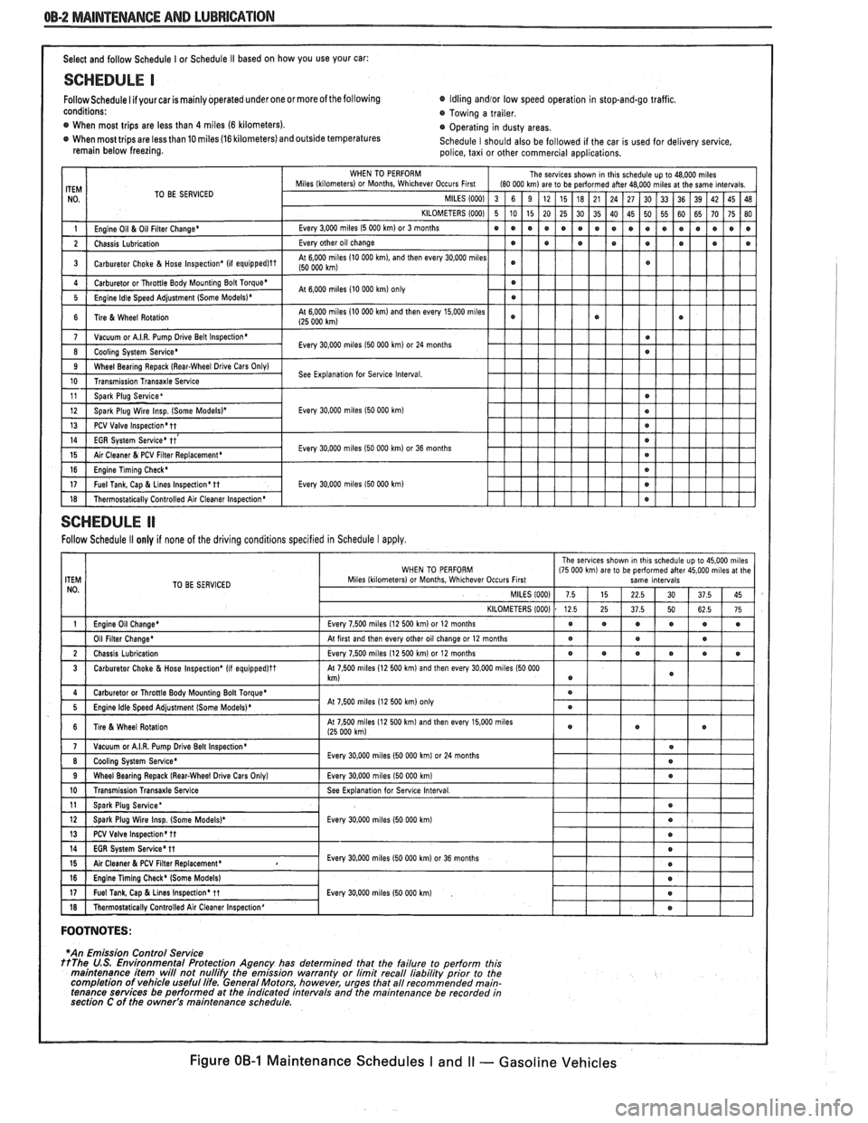
Select and follow Schedule I or Schedule I1 based on how you use your car:
SCHEDULE I
Follow Schedule I if your car is mainly operated under one or moreof the following Idling andlor low
speed operation in stop-and-go traffic.
conditions: Towing a trailer.
@ When most trips are less than 4 miles (6 kilometers).
Operating in dusty areas.
When most trips are less than 10 miles (16 kilometers) and outside temperatures
Schedule I should also be followed if the car is used for delivery service,
remain below freezing.
police, taxi or other commercial applications.
TO BE SERVICED
Every
30.000 miles I50 000 km)
Every 30,000 miles I50 000 km) or 36 months
Every
30,000 miles 150 000 km)
SCHEDULE ll
Follow Schedule II only if none of the driving conditions specified in Schedule I apply.
TO BE SERVICED
At
7 500 miles 12 500 km on1
FOOTNOTES:
I
*An Emission Control Service ttThe U.S. Environmental Protection Agency has determined that the failure to perform this
maintenance item will not nullifv the emission warrantv or limit recall liabilitv orior to the
completion of vehicle useful life. General Motors, however, urges that all recommended main-
tenance services be performed at the indicated intervals and the maintenance be recorded in
section C of the owner's
ma~ntenance schedule.
Figure OB-1 Maintenance Schedules I and I1 - Gasoline Vehicles
Page 21 of 1825
OB-4 MAINTENANCE AND LUBRICATION
Tire and wheel operation - Be alert to a vibra-
tion of the steering wheel or seat at normal highway
speeds. This may mean a wheel balance is needed. Also, a
pull right or left on a straight, level road may show the
need for
a tire pressure adjustment or wheel alignment.
Steering system operation - Be alert to
changes in steering action. An inspection is needed when
the steering wheel is harder to turn or has too much free
play or if unusual sounds are noted when turning or
parking.
Headlight aim operation - Take note of light
pattern occasionally. If beam aim doesn't look right,
headlights should be adjusted.
AT EACH FUEL FILL
Engine oil level check - Check engine oil level
and add if necessary. See your Owner's
Manual for further
details.
NOTICE: A large loss in this system may indicate a
problem. Have it inspected and repaired at once.
Engine coolant level and condition - Check
engine coolant level in coolant reservoir tank and add if
necessary. Replace if dirty or rusty. See your Owner's
Manual for further details.
NOTICE: A large loss in this system may indicate a
problem. Have it inspected and repaired at once.
Windshield washer fluid level check -- Check
washer fluid level in container and add if necessary.
Hood latch operation - When opening hood on
cars equipped with hoods that open from the front, note
the operation of secondary latch. It should keep hood from
opening all the way when primary latch is released. Make
sure that hood closes firmly.
AT LEAST MONTI-ILY
Tire and wheel inspection and pressure
check--
Check tires for abnormal wear or damage. Also,
check for damaged wheels. Keep pressures as shown on
Tire Placard on the driver's door (include spare unless it is
a stowaway). Pressure should b\: checked when tires are
"cold". See "Tires" in Owner's Manual for further
infomation.
Light operation check - Check operation of
license plate light, side-marker lights, headlights includ-
ing high beams, parking lights, taillights, brake lights.
turn signals, backup lights, instrument panel and interior
lights and hazard warning flashers.
Fluid leak check - After the car has been parked
for a while, inspect the surface beneath the car for water,
oil, fuel or other fluids. Water dripping from the air
conditioning system after use is normal. If you notice fuel
leaks or fumes, the cause should be found and corrected at
once.
AT LEAST TWICE A YEAR (FOR EXAMPLE,
EVERY SPRING AND FALL)
Power steering pump fluid level check --
Check power steering pump fluid level in accordance with
Owner's Manual instructions and keep at proper level.
NOTICE: A large loss in this system may indicate a
problem. Have it inspected and repaired at once.
Brake master cylinder reservoir fluid level
check ---- Check fluid and keep at proper level. Note: It is
normal for the brake fluid level to go down slightly as the
brake pads wear
- so be sure to keep reservoir filled.
NOTICE: A large loss in this system may indicate a
problem. Have
it inspected and repaired at once.
Clutch system service --- manual transmis-
sionltransaxle --- For cars equipped with hydraulic
clutch system, check the reservoir fluid level and add fluid
as required. All others, check clutch pedal free travel and
adjust as necessary. See your Owner's Manual for further
details.
~
NOTICE: A large loss in this system may indicate a
problem. Have it inspected and repaired at once.
Weatherstrip Lubrication - Clean surface and
then apply a thin film of silicone grease with a clean cloth.
EACH TIME OIL IS CHANGED
Automatic and manual transmissionltrans-
axle fluid level check - Check transmission/transaxle
fluid level and add as required. (Corvette only) if equipped
with manual transmission
- check fluid in the overdrive
unit and add as required.
NOTICE: A large loss in this system may indicate a
problem. Have
it inspected and repaired at once.
Brake systems inspection - For convenience,
the following should be done when wheels are removed
for rotation: Inspect lines and hoses for proper hookup,
binding, leaks, cracks, chafing, etc. Inspect disc brake
pads for wear and rotors for surface condition. Also in-
spect drum brake linings for wear and cracks. Inspect
other brake parts, including drums, wheel cylinders, park-
ing brake, etc. at the same time. Check parking brake
adjustment.
INSPECT BRAKES MORE OFTEN IF DRIVING
HABITS OR CONDITIONS RESULT IN FREQUENT
BRAKING.
Steering, suspension and front drive axle
boot and seal inspection
- Inspect front and rear
suspension and steering system for damaged, loose or
missing parts, signs of wear or lack of lubrication. Inspect
power steering lines and hoses for proper hookup, bind-
ing, leaks, cracks, chafing, etc. (On cars equipped with
manual steering gear, check for seal leakage.) On
front-
wheel-drive cars, clean then inspect drive axle boot seals
for damage, tears or leakage. Replace seals if necessary.
Exhaust system inspection - Inspect complete
system. Inspect body near the exhaust system. Look for
broken, damaged, missing or out-of-position parts as well
as open seams, holes, loose connections or other condi-
tions which could cause a heat buildup in the tloor pan or
could let exhaust fumes seep into the trunk or passenger
compartment.
Page 22 of 1825
MAINTENANCE AND LUBRICATION OB-5
Throttle linkage inspection -- Inspect for inter-
ference, binding, damaged or missing parts.
Engine drive belts inspection - Inspect all
belts for cracks, fraying and wear. Adjust or replace as
needed.
Rear axle service (if equipped) - Check gear
lubricant level and add if needed. For cars equipped with a
limited slip rear axle, fluid does not require changing
(except Caprice and Corvette
- change fluid and required
additive at first
7,500 miles (12 500 km). See your
Owner's Manual or "Recommended Fluids
& Lubricants
Chart" in this section.
IF YOU USE YOUR GAR TO PULL A TRAILER,
CHANGE GEAR LUBRICANT EVERY 7,500 MILES
(12 500 KM).
NOTICE: A large loss in this system may indicate a
problem. Have it inspected and repaired at once.
Power antenna - Clean and then lubricate power
antenna mast. The proper lubricant as shown in Figure
OB-2 should be used.
AT LEAST ONCE A YEAR
Lap and shoulder belts condition and opera-
tion
- Inspect belt system, including webbing, buckles,
latch plates, retractors, guide loops and anchors.
Moveable head restraint operation - On cars
with moveable restraints, make sure restraints stay in the
desired position. (See adjustment instructions in your
Owner's Manual.)
Seatback latch and recliner operation on
cars equipped
with recliner seat --- Be sure seat-
backs latch on those cars with folding seats using mechan-
ical latches. Make sure the recliner is holding by pushing
and pulling on the top of the
seatback while it is reclined.
See your Owner's Manual for seat operating information.
Spare tire and jack storage- Be alert to rattles
in rear of car. Make sure the space tire, all jacking equip-
ment, any tire inflator and any covers or doors are securely
stowed at all times. Oil jack ratchet or screw mechanism
after each use.
Key lock service - Lubricate key lock cylinder at
least annually.
Body lubrication service - Lubricate all body
door hinges including the tailgate or hatchback lid (if
equipped). Also lubricate the body hood, fuel door and
rear compartment hinges and latches including interior
glove box and counsel doors, and any folding seat
hardware.
"Fansmissionltransaxle neutral or clutch
starl switch operation
CAUnON: Before pedorming the follow-
ing safety switch check, be sure to have
enough room around the car. Then, firmly
apply both the parking brake (see your
Owner's Manual for procedure) and the
regular brakes. Do not use the accelerator pedal.
If the engine
starls, be ready to turn
off the ignition promptly. Take these pre-
cautions because the car could move
without warning and possibly cause per-
sonal injury or properly damage. On auto-
matic transmissionltransaxle cars, try to
starl the engine in each gear. The starler
should crank only in "Park" or "Neutral."
On manual transmissionltransaxle cars,
place the
shiR lever in "Neutral," push the
clutch halfway and try to starl. The starler
should crank only when the clutch is fully
depressed.
Steering column lock operation
- While
parked, try to turn key to "Lock" in each gear range. The
key should turn to "Lock" only when gear is in "Park" on
automatic or "Reverse" on manual
transmissionltransax-
le. On cars with key release lever, try to turn key toULock"
without depressing the lever. The key should turn to
"Lock" only with the key lever depressed. On all vehicles,
the key should come out only in "Lock."
Parking brake and transmissionltransaxle
"Park" mechanism operation
CAUT1ON:Before checking the holding
ability of the parking brake and automatic
transmissionltransaxle "Park" mecha-
nism, park on a fairly steep hill with
enough room for movement in the down-
hill direction. To reduce the risk of person-
al injury or property damage, be prepared
to apply the regular brakes promptly if the
car begins to move.
To check the parking brake, with the engine running and
transmission/transaxle in "Neutral." slowly remove foot
pressure from the regular brake pedal (until the car is held
by only the parking brake).
To check the automatic transmissionltransaxle "Park"
mechanism holding ability, release all brakes after shift-
ing the transmissionltransaxle to "Park."
ljnderbody flushing - At least every spring,
tlush from the underbody with plain water any corrosive
materials used for ice and snow removal and dust control.
Take care to thoroughly clean any areas where mud and
other debris can collect.
Sediment packed in closed areas
of the vehicle should be loosened before being flushed.
Engine cooling system service - Inspect
coolant and freeze protection. If dirty or rusty, drain, flush
and refill with new coolant. Keep coolant
at the proper
mixture as specified in your Owner's Manual. This pro-
vides proper freeze protection. corrosion inhibitor level
and engine operating temperature. Inspect hoses and re-
place if cracked. swollen or deteriorated. Tighten hose
clamps. Clean outside of radiator and air conditioning
condensor. Wash radiator filler cap and neck.
To help
ensure proper operation. a pressure test of both the cooling
system and cap is also recommended. (See maintenance
schedule charts in Figure
OB-l for the recommended
coolant change interval.)
Page 45 of 1825
18-2 AIR CONDITIONING
SYSTEM GONIPONENE - FFUNCnIONAL
Compressor
All compressors are belt driven from the engine
crankshaft through the compressor clutch pulley. The
compressor pulley rotates without driving the com-
pressor shaft until an electromagnetic clutch coil is
energized. When voltage is applied to energize the
clutch coil, the clutch plate and hub assembly is
drawn rearward toward the pulley. The magnetic
force locks the clutch plate and pulley together as one
unit to drive the compressor shaft.
As the compressor shaft is driven, it compresses
the low-pressure refrigerant vapor from the evaporator
into a high-pressure, high-temperature vapor. Carried
with the refrigerant is the refrigerant oil which is used
to lubricate the compressor. Complete compressor
overhaul procedures can be found in Section
ID of the
General Service Manual.
Pressure Relief Valve
The compressor is equipped with a pressure
relief valve which is placed in the system as a safety
factor. Under certain conditions, the refrigerant on the
discharge side may exceed the designed operating
pressure. To prevent system damage, the valve is
designed to open automatically at approximately
3036
kPa (440 psi). Conditions that might cause this valve
to open (defective high pressure cut-off switch, inop-
erative electric cooling fan, etc.) should be corrected,
and the refrigerant oil and refrigerant should be
replaced as necessary.
A muffler is used on some refrigerant systems to
reduce compressor noises from high or low pressure
vibrations.
Condenser Gore
The condenser assembly in front of the radiator
is made up of coils which carry the refrigerant TO
cooling fins to provide rapid transfer of heat. The air
passing through the condenser cools the high-pressure
refrigerant vapor causing it to condense to a liquid.
Expansion (Orifice) Tube
The plastic expansion tube, with its mesh screen
and orifice, is located in the evaporator inlet pipe at
the liquid line connection. It provides a restriction to
the high-pressure liquid refrigerant in the liquid line,
metering the flow of refrigerant to the evaporator as a
low-pressure liquid. The expansion tube and orifice
are protected from contamination by filter screens on
both inlet and outlet sides. The tube is serviced only
as a replacement assembly.
When the engine is turned "OFF" with the
A/C
system operating, the refrigerant in the system will
flow from the high-pressure side of the expansion tube (orifice) to the low-pressure side until the pressure
is
equalized. This may be detected as a faint sound of
liquid flowing (hissing) for 30 to
60 seconds and is a
normal condition.
Evaporator Gore
The evaporator is a device which cools and
dehumidifies the air before it enters the car. High-
pressure liquid refrigerant flows through the expan-
sion tube (orifice) into the low-pressure area of the
evaporator. The heat in the air passing through the
evaporator core is transferred to the cooler surface of
the core, thereby cooling the air. As the process of
heat transfer from the air to the evaporator core sur-
face is taking place, any moisture (humidity) in the air
condenses on the outside surface of the evaporator
core and is drained off as water.
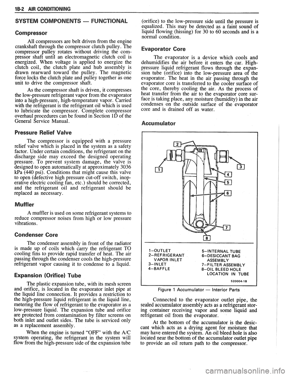
Accumulator
5-INTERNAL TUBE
2-REFRIGERANT 6-DESICCANT BAG
VAPOR INLET ASSEMBLY
7-FILTER ASSEMBLY
8-OIL BLEED HOLE
LOCATION IN TUBE
520004-1 8
Figure 1 Accumulator - Interior Parts
Connected to the evaporator outlet pipe, the
sealed accumulator assembly acts as a refrigerant stor-
ing container receiving vapor and some liquid and
refrigerant oil from the evaporator.
At the bottom of the accumulator is the desic-
cant which acts as a drying agent for moisture that
may have entered the system. An oil bleed hole is also
located near the bottom of the accumulator outlet pipe
to provide an oil return path to the compressor.
Page 61 of 1825
LlOQllD LiNE FILTER INSTALLATION
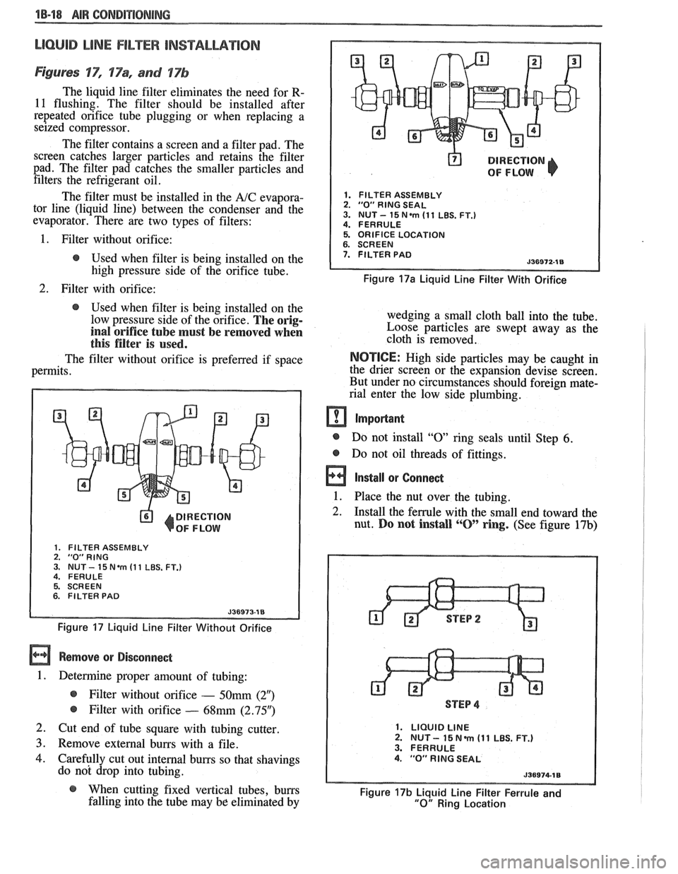
Figures 'IT", 17% and 17b
The liquid line filter eliminates the need for R-
11 flushing. The filter should be installed after
repeated orifice tube plugging or when replacing a
seized compressor.
The filter contains a screen and a filter pad. The
screen catches larger particles and retains the filter
pad. The filter pad catches the smaller particles and filters the refrigerant oil.
The filter must be installed in the
A/C evapora-
tor line (liquid line) between the condenser and the
evaporator. There are two types of filters:
@ DIRECTION
OF FLOW
1. FILTER ASSEMBLY 2. "0" RlNG SEAL 3. NUT- 15N.m (11 LBS. FT.) 4. FERRULE
1. Filter without orifice: 5. ORIFICE LOCATION
@ Used when filter is being installed on the 7. FILTER PAD
high pressure side of the orifice tube. Figure 17a Liquid Line Filter With Orifice
2. Filter with orifice:
@ Used when filter is being installed on the
low pressure side of the orifice.
The orig-
inal orifice tube must be removed when
this filter is used.
The filter without orifice is preferred if space
permits.
DIRECTION
OF FLOW
1. FILTER ASSEMBLY 2. "0"RING 3. NUT - 15 Nem (1 1 LBS. FT.) 4. FERULE
5. SCREEN
6. FILTER PAD
Figure 17 Liquid Line Filter Without Orifice
Remove or Disconnect
1. Determine proper amount of tubing:
@ Filter without orifice - 50mm (2")
@ Filter with orifice - 68mm (2.95")
2. Cut end of tube square with tubing cutter
3. Remove external burrs with a file.
4. Carefully cut out internal burrs so that shavings
do not drop into tubing. wedging a small cloth ball
into the tube.
Loose particles are swept away as the
cloth is removed.
NOTICE: High side particles may be caught in
the drier screen or the expansion devise screen.
But under no circumstances should foreign mate-
rial enter the low side plumbing.
m Important
@ Do not install "0 ring seals until Step 6.
@ Do not oil threads of fittings.
a Install or Connect
1. Place the nut over the tubing. -
2. Install the ferrule with the small end toward the
nut.
Do not install ""0' ring. (See figure 17b)
STEP 4
1. LIQUID LINE 2. NUT - 15 N m (1 1 LBS. FT.) 3. FERRULE 4. "0" RlNG SEAL
@ When cutting fixed vertical tubes, burrs Figure 17b Liquid Line Filter Ferrule and falling into the tube may be eliminated by "0" Ring Location
Page 91 of 1825
4 Dl-I 2 R-4 AIR CONDITIONING COMPRESSOR OVERHAUL
MAJOR REPAIR PROCEDURES
Service repair procedures to the
Compressor Shaft Seal,
Pressure Relief Valve
or disassembly
of the Internal Compressor
Cylinder and Shaft Assembly are considered
"MAJOR" SINCE THE REFRIGERATION
SYSTEM MUST BE DISCHARGED,
EVACUATED AND RECHARGED to complete
service and/or because major internal
operating and sealing components of the
compressor are being disassembled and
serviced.
When replacing the shaft seal assembly or
pressure relief valve, even if the compressor remains on
the vehicle during the operation, it will be necessary to
discharge the system of refrigerant (see Section
1B).
Other than clutch repair procedures, the same holds
true for any disassembly of the compressor.
If the compressor shell, front head or cylinder
and shaft assembly are to be serviced or replaced, the
oil in the compressor must be drained, measured and
replaced (see Section
1B) to determine addition of
proper oil quantity to new assembly.
A clean workbench, preferably covered with a
sheet of clean paper, orderliness in the work area and
a place for all parts being removed and replaced is of
great importance, as is the use of the proper, clean
service tools.
NOTICE: Any attempt to use make-shift or
inadequate equipment may result in damage
and/or improper compressor operation.
All parts required for servicing the internal
compressor are protected by a preservation process and
packaged in a manner which will eliminate the
necessity of cleaning, washing or flushing of the parts.
The parts can be used in the internal assembly just as
they are removed from the service package.
Seals and
protective packaging should be left in tact un
ti1 just
prior to installation.
SI-IAFT SEAL
Fig. 35 thru 40
Shaft Seal Design
The shaft seal is a one piece design.
Seal Leak Detection
A shaft seal should not be changed because of an
oil-line on the hood insulator. The Seal is designed to
seep some oil for lubrication purposes. Only change a
Shaft Seal when a leak is detected by evidence of oil
sprayed in large amounts and then only after actual
refrigerant leakage is found by using an approved leak
Detector such as J-29547 or equivalent.
Should an R-4 compressor shaft seal ever have to
be replaced, the accumulator in this R-4 system must
also be removed from the vehicle. The oil in the
accumulator then must be drained, measured and
replaced according to the directions in Section
1B to
determine oil loss.
On-Car
Remove
or Disconnect
1. Discharge A/C system
2. Loosen and reposition compressor in mounting
brackets
3. Clutch Plate and Hub assembly
4. Shaft seal seat retainer ring, using Snap Ring
Pliers J-5403-A
5. Thoroughly clean inside of compressor neck area
and O-ring groove surrounding the shaft, the
exposed portion of the seal seat and the shaft
itself. Any dirt or foreign material getting into
compressor may cause damage.
6. Remove Lip Seal:
e Fully engage the knurled tangs of Seal
Remover-Installer J-23 128-A into the
recessed portion of the Seal by turning the
handle clockwise. Remove the Seal from the
compressor with a rotary-pulling motion.
Discard the Seal. The handle must be
hand-tightened securely. Do not use a
wrench or pliers.
7. Discard the seal seat O-ring from the compressor
neck using 0-Ring Remover J-9553-01.
8. Recheck the shaft and inside of the compressor
neck and O-ring groove for dirt or foreign
material and be sure these areas are perfectly
clean before installing new parts.
Inspection
Seals should not be reused. Always use a new
specification service seal kit on rebuild. Care should be
taken to prevent damage to the lip of the one piece seal.
Make sure that the Seal Seat and Seal Lip are free of
lint and dirt that could damage the seal surface or
prevent sealing.
On-Car
Install
or Connect
1. Dip
the new seal O-ring in clean 525 viscosity
refrigerant oil and assemble onto 0-Ring
Installer J-33011.
2. Insert
the 0-Ring Installer
5-3301 1 completely
down into the compressor neck until the Installer
"bottoms." Lower the moveable slide of the
0-Ring Installer to release the 0-Ring into the
seal seat O-ring lower groove. (The compressor
neck top groove is for the shaft seal retainer ring.)
Rotate the Installer to seat the O-ring and remove
the Installer.
3. Prepare Lip Seal:
Assemble seal to Seal Installer J-23128-A,
by turning handle clockwise, and then push
Seal Protector J-34614, into seal lip. The
stamped steel case side of the lip seal must
be engaged with knurled tangs of installer so
that flared-out side of lip seal is facing and
installed towards the compressor.
4. Install Lip Seal:
Page 111 of 1825
2C-4 CHASSIS SHEET METAL
3. Clean area to be repaired.
4. Mix and apply the repair material by using a
putty knife or rubber squeegee.
5. Work the material into the repair and build up
the desired contour. For deep filling, and on
vertical surfaces, several layers may be
required.
6. Feather-sand damaged area with No. 200 sand-
paper and finish-sand with No. 320 sandpaper.
7. Prepare repaired area for refinishing. Refinish
with acrylic lacquer as described below.
1. THOROUGHLY CLEAN the entire surface
area, using Naphtha or equivalent solvent, to
insure a surface free of contamination.
2. To promote paint adhesion, a light scuff-sand-
ing of the surface with
#400-grit sandpaper is
recommended.
3. Repeat cleaning of the surface.
4. Color coat with acrylic lacquer for proper color
match.
5. Allow to dry thoroughly, rub out and polish.
PAINT REFINISHING PROCEDURES FOR
URETHANE, P.V.C. AND T.P.R. SURFACES
Urethane material will withstand minor impact
and the resultant damage, such as occurs in parking
lots, by recovering its original shape. Its Endura paint
film responds to impact in a similar manner without
cracking or splitting. If, however, an area of damage
in the Urethane bumper or panel does not recover its
shape, or the surface is punctured, gouged or torn, a
repair system has been developed to restore the origi-
nal shape and appearance of the urethane-base
material.
CALSVON: There are a number of paint
systems available For service use; how-
ever,
many require additives containing
isocyanates.
It is essential that all rec-
ommendations and warnings listed on
the container label for
materials
seleded be followed.
CAUTION: If the paint system selected
specifies an additive containing
isocya-
nates, it is mandatory that adequate
respiratory protection be worn. An
example of such protection
is an air line
respirator with a
full hood or half mask.
If not
avaiable, use a vaporlpaHiculate
respirator that the respirator supplier
recommends as
efFective for isocyanate
vapors and mists (unless local
regula-
tions prevail).
Such protection should be worn during the
entire painting process. Persons with respiratory
problems, or those
allergic to isocyanates must not
be exposed to isocyanate vapors or spray mist.
REPAIRING & REFINISHING URETHANE
BUMPERS AND FRONT END PANELS
Required Materials:
1. 3M No. 8101 Structural Adhesive, or
equivalent.
2. Color Coat - Dexlar (DuPont) Flexible Finish
Enamel Color Coat, or Ditzler Elastomeric
Enamel Color Coat or equivalent.
3. Additive
- DuPont 792s Centari Hardener,
or
Ditzler
DXR-80 Delthane Additive or
equivalent.
4. Thinner
- DuPont 3608s Acrylic
Lacquer
Thinner, or Ditzler Delstar DTR 601 Acrylic
Enamel Reducer or equivalent.
NOTICE: Use the same brand name materials for
the color coat, additive, and thinner.
5. A wax and adhesive cleaner.
Equipment Needed:
1. Wooden spatula (enclosed in repair package).
2. Heat lamp.
3. 36 grit 180-A, 240-A, and 320-A grit disc
sandpaper.
4. Random orbital-type sander.
5. Body repair tape.
6. Suction spray gun (same nozzle and air cap
combination as used for acrylic).
Repair Procedure
There are three types of repairable damage on
urethane material. They are a puncture, a gouge and a
tear.
Following is the basic repair procedure for
repairing these types of damages.
1. Clean the damaged area with 3M #8984 Gen-
eral Purpose Adhesive Cleaner or equivalent. If
the damage is through the thickness of the part,
clean both sides.
Grind away damaged material with a
36 grit
disc. Feather edge the paint around the damage
using a
1808 grit disc.
2. If the part has a puncture or tear, file or rout out
the area where joint line will be. Bevel the edge
of the part with the open edge towards the side
to be filled (fill from the side with easiest
access). Clean the repair area with a clean dry
rag.
3. Apply 3M #6935 Auto Body Repair Tape, or
equivalent, to the underside of the repair area to
backup the repair material.
NOTICE: Before going to the next step, be sure
all of the paint (both topcoat and primer) has been
removed from the area where the structural adhe-
sive is to be applied.