1988 PONTIAC FIERO oil reset
[x] Cancel search: oil resetPage 755 of 1825
6E3-C2-20 2.8L (VIN S) DRIVEABILITY AND EMISSIONS
AIR THROTTLE FLOW BODY
LD START VALVE
8-5 BLUNVHT
BLUIBLK
GRMNVHT
. GRNIBLK
ECM
.
IAC COIL
"A" HI
IAC COIL "A" LO
IAC COIL "B" HI
C3 IAC COIL "B" LO
7-1 6-87
55 1800-6E
CHART C-2C
IDLE AIR CONTROL
2.8L (VIN S) ""F-SERIES (PORT)
Circuit Description:
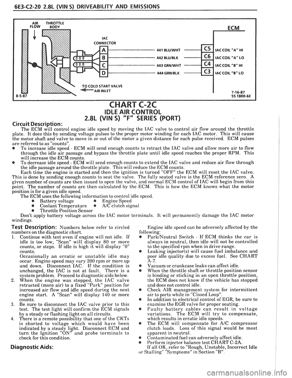
The ECM will control engine idle speed by moving the IAC valve to control air flow around the throttle
plate. It does this by sending voltage pulses to the proper motor winding for each IAC motor. This will cause
the motor shaft and valve to move in or out of the motor a given distance for each pulse received. ECM pulses
are referred to as "counts".
@ To increase idle speed - ECM will send enough counts to retract the IAC valve and allow more air to flow
through the idle air passage and bypass the throttle plate until idle speed reaches the proper RPM. This
will increase the ECM counts.
@ To decrease idle speed - ECM will send enough counts to extend the IAC valve and reduce air flow through
the idle passage around the throttle plate. This will reduce the ECM counts.
Each time the engine is started and then the ignition is turned "OFF" the ECM will reset the IAC valve.
This is done by sending enough counts to seat the valve. The fully seated valve is the ECM reference zero. A
given number of counts are then issued to open the valve, and normal ECM control of IAC will begin from this
point. The
number of counts are then calculated by the ECM. This is how the ECM knows what the motor
position is for
a given idle speed.
The ECM uses the following information to control idle speed.
@ Battery voltage @ Engine Speed
@ Coolant Temperature @ A/C clutch signal
@ Throttle Position Sensor
Don't apply battery voltage across the IAC motor terminals. It will permanently damage the IAC motor
windings.
Test Description: Numbers below refer to circled Engine
idle speed can be adversely affected by the
numbers on the diagnostic chart. following:
1. Continue
with test even if engine will not idle. If @ ParUNeutral Switch - If ECM thinks the car is
idle is too low, "Scan" will display
80 or more always
in neutral, then idle will not be controlled
counts, or steps. If idle is high it will display
"0" to the specified rpm when in drive range.
counts.
@ Leaking injector(s) will cause fuel imbalance and
Occasionally an erratic or unstable idle may poor
idle quality due to excess fuel. See CHART
occur. Engine speed may vary
200 rpm or more up A-7.
and down. Disconnect
EAC. If the condition is @ Vacuum or crankcase leaks can affect idle.
unchanged, the IAC is not at fault. There is
a @ When the throttle shaft or throttle position sensor
system problem. Proceed to diagnostic aids below. is
binding or sticking in an open throttle position,
2. When the engine was stopped, the IAC valve the
ECM does not know if the vehicle has stopped
retracted (more air) to a fixed "Park" position for and does not control idle.
increased air flow and idle speed during the next
@ Check AIR management system for intermittent
engine start. A "Scan" will display
140 or more air
to ports while in "Closed Loop".
counts. @ In addition to electrical control of EGR, be sure to
3. Be sure to disconnect the IAC valve prior to this examine the
EGR valve for proper seating.
test. The test light will confirm the ECM signals @ Faulty battery cables can result in voltage
by a steady or flashing light on all circuits. variations. The
ECM will try to compensate,
4. There is a remote possibility that one of the CKTs which results in erratic idle speeds.
is shorted to voltage which would have been @ The ECM will compensate for A/C compressor
indicated by a steady light. Disconnect ECM and clutch
loads. Loss of this signal would be most
turn the Ignition "ON" and probe terminals to apparent
in neutral.
check for this condition.
@ Contaminated fuel can adversely affect idle. @ Perform in
or Stalling" "Svmptoms" in Section "B".
Page 847 of 1825
6E3-A-44 5.0b (VIN F) & 5.7L (VIN 8) DRIVEABILITY AND EMISSIONS
SYSTEM GND
SYSTEM GND
BLUNVHT 450 SYSTEM GND
BURN-OFF CONTROL CUT
CODE 34
MASS AIR FLOW (MAF) SENSOR CIRCUIT
(GMISEC LOW)
5.OL (VIN F) & 5.7L (\/IN 8) "F"" SERIES (PORT)
Circuit Description:
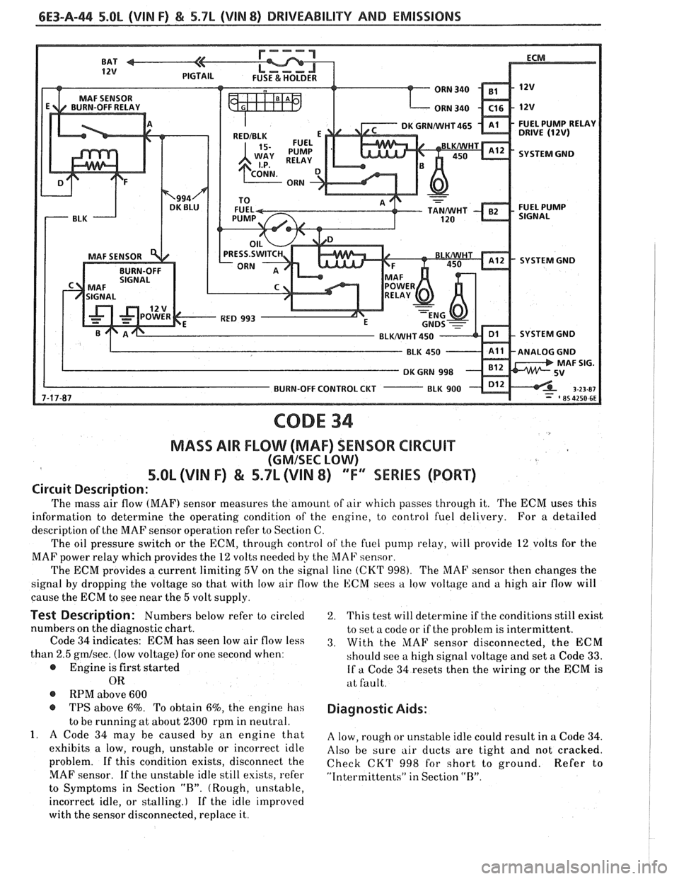
The mass air flow (MAF) sensor measures the amount of air which passes through it. The ECM uses this
information to determine the operating condition of the engine, to control fuel delivery. For a detailed
description of the MAF sensor operation refer to Section C.
The oil pressure switch or the ECM, through control
of the fuel pump relay, will provide 12 volts for the
MAF power relay which provides the
12 volts needed by the MAF sensor.
The ECM provides a current limiting
5V on the signal line (CKT 998). The MAF sensor then changes the
signal by dropping the voltage so that with low air flow the ECM sees
a low voltage and a high air flow will
cause the ECM to see near the
5 volt supply.
Test Description: Numbers below refer to circled
numbers on the diagnostic chart.
Code
34 indicates: ECM has seen low air flow less
than
2.5 gmlsec. (low voltage) for one second when:
@ Engine is first started
OR
@ RPM above 600
@ TPS above 6%. To obtain 6%, the engine has
to be running at about
2300 rpm in neutral.
1. A Code 34 may be caused by an engine that
exhibits a low, rough, unstable or incorrect idle
problem. If this condition exists, disconnect the
MAF sensor. If the unstable idle still esists, refer
to Symptoms in Section
"R". (Rough, unstable,
incorrect idle, or stalling.) If the idle improved
with the sensor disconnected, replace it.
2. This test will determine if the conditions still exist
to set a code or if the problem is intermittent.
3. With the MAF sensor disconnected, the ECM
should see a high signal voltage and set a Code
33.
If a Code 34 resets then the wiring or the ECM is
at fault.
Diagnostic Aids:
A low, rough or unstable idle could result in a Code 34.
Also be sure air ducts are tight and not cracked.
Check CKT
998 for short to ground. Refer to
"Intermittents" in Section "R".
Page 907 of 1825
6E3-C2-20 5.0L (VIN F) & 5.7L (WIN 8) DRIVEABILITY AND EMISSIONS
CONNECTOR - 441 BLUMlHT C5 IAC C0lL1'A" HI - 442 BLUIBLK C6 IAC COIL "A" LO - 443 GRNMlHT C4 IAC COIL "B" HI - 444 GRNIBLK C3 lAC COIL "B" LO v
START VALVE
CHART C-2C
IDLE AIR CONTROL (IAC) SYSTEM CHECK
S.OL (VIN F) & 5.7L (VIN 8) "F'" SERIES (PORT)
Circuit Description:
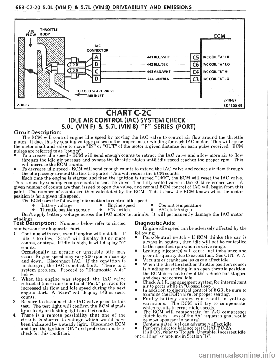
The ECM will control engine idle speed by moving the IAC valve to control air flow around the throttle
plates. It does this by sending voltage pulses to the proper motor winding for each IAC motor. This will cause
the motor shaft and valve to move
"IN" or "OUT" of the motor a given distance for each pulse received. ECM
pulses are referred to as "counts".
@ To increase idle speed - ECM will send enough counts to retract the IAC valve and allow more air to flow
through the idle air passage and bypass the throttle plates until idle speed reaches the proper rpm. This
will increase the ECM counts.
e To decrease idle speed - ECM will send enough counts to extend the IAC valve and reduce air flow through
the idle passage around the throttle plates. This will reduce the ECM counts.
Each time the engine is started and then the ignition is turned "OFF", the ECM will reset the IAC valve.
This is done by sending enough counts to seat the valve.
The fully seated valve is the ECM reference zero. A
given number of counts are then issued to open the valve, and normal ECM control of IAC will begin from this
point. The
number of counts are then calculated by the ECM. This is how the ECM knows what the motor
position is for a given idle speed.
The ECM uses the following information to control idle speed.
@ Battery voltage @ Engine speed @ Coolant temperature @ Throttle position sensor @ PIN switch e A/C clutch signal
Don't apply battery voltage across the IAC motor terminals. It will permanently damage the IAC motor
windin s. Test 6escription: Numbers below refer to circled
numbers on the diagnostic chart.
1. Continue with test, even if engine will not idle. If
idle is too low, "Scan" will display 80 or more
counts, or steps. If idle is high, it will display
"0"
counts.
Occasionally an erratic or unstable idle
[nay occur. Engine speed may vary 200 rpm or more up
and down. Disconnect IAC. If the condition is
unchanged, the IAC is not at fault.
There is a
system problem. Proceed to "Diagnostic Aids"
below.
2. When the engine was stopped, the IAC valve
retracted (more air) to
a fixed "Park" position for
increased air flow and idle speed during the next
engine start. A "Scan" will display 140 or more
coiints. 3. Be sure to disconnect the IAC valve prior to this
test.
The test light will confirm the ECM signals
by a steady or flashing light on all circuits.
4. There is a remote possibility that one of the
circuits is shorted to voltage which would have
been indicated by a steady light. Disconnect ECM
and turn the ignition "ON" and probe terminals to
check for this condition.
Diagnostic Aids:
Engine idle speed can be adversely affected by the
following:
@ ParMNeutral switch - If ECM thinks the car is
always in neutral, then idle will not be controlled
to the specified rpm when in drive range.
@ Leaking injector(s) will cause fuel imbalance and
poor idle quality due to excess fuel. See CHT.
A-7. @ Vacuum or crankcase leaks can affect idle. @ Whenthethrottleshaftorthrottlepositionsensor
is binding or sticking in an open throttle position,
the ECM does not know if the vehicle has stopped
and does not control idle.
@ Check A.I.R. management s stem for intermittent
air to orts while in "~losed~oo~". @ In ad&tion to electrical control of EGR, be sure to
examine the EGR valve for proper seating.
@ Faulty battery cables can result in voltage
variations. The ECM will try to compensate,
which results in erratic idle speeds.
@ 'I'he ECM will com ensate for A/C com ressor
clutch loacls. [.ass ofthe NC request sign8 would
he 11lost apparent, in neutral. @ Contalninatecl fuel can adverse1 affect idle. @ Perform i~!jector balance test C~ART C-2A. If ,111 OK, refer to "Rough, Unstable, Incorrect Idle or St ,tllinqW SJ tnptcfinsiin S~'ction "11''.
Page 1057 of 1825
700.R4-6 AUTOMATIC TRANSMISSION
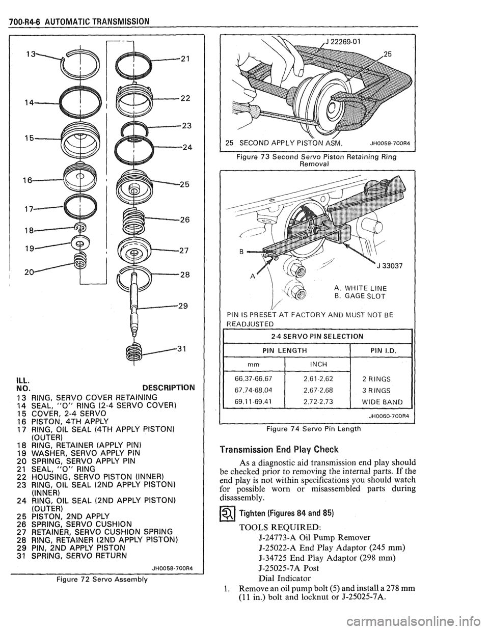
ILL. NO. DESCRIPTION
13 RING, SERVO COVER RETAINING
14 SEAL, "0" RING (2-4
SERVO COVER)
15 COVER, 2-4 SERVO
16 PISTON, 4TH APPLY 17 RING, OIL SEAL (4TH APPLY PISTON)
(OUTER)
18 RING, RETAINER (APPLY PIN)
19 WASHER, SERVO APPLY PIN
20 SPRING, SERVO APPLY PIN
21 SEAL,
"0" RING 22 HOUSING, SERVO PISTON (INNER) 23 RING, OIL SEAL (2ND APPLY PISTON)
(INNER)
24 RING, OIL SEAL
(2ND APPLY PISTON)
(OUTER)
25 PISTON, 2ND APPLY
26 SPRING, SERVO CUSHION
27 RETAINER, SERVO CUSHION SPRING
28 RING, RETAINER
(2ND APPLY PISTON)
29 PIN, 2ND APPLY PISTON 31 SPRING, SERVO RETURN
JH0058-700R4
Figure 72 Servo Assembly Figure
73 Second
Servo Piston Retaining Ring
Removal
A. WHITE LINE B GAGE SLOT
PIN IS PRESET AT FACTORY AND MUST NOT BE
I I 2-4 SERVO PIN SELECTION I I
I I PIN LENGTH 1 PIN I.D. 11
Figure 74 Servo Pin Length
Transmission End Play Check
As a diagnostic aid transmission end play should
be checked prior to removing the internal parts. If the
end play is not within specifications you should watch
for possible worn or misassembled parts during
disassembly.
Tighten (Figures 84 and 85)
TOOLS REQUIRED:
J-24773-A Oil Pump Remover
5-25022-A End Play Adaptor (245 mm)
5-34725 End Play Adaptor (298 mm)
5-25025-7A Post
Dial Indicator
1. Remove an oil pump bolt (5) and install a 278 mm
(11 in.) bolt and locknut or J-25025-7A.
Page 1422 of 1825
INSTRUMENT PANEL: DlGlTAL CLUSTER a
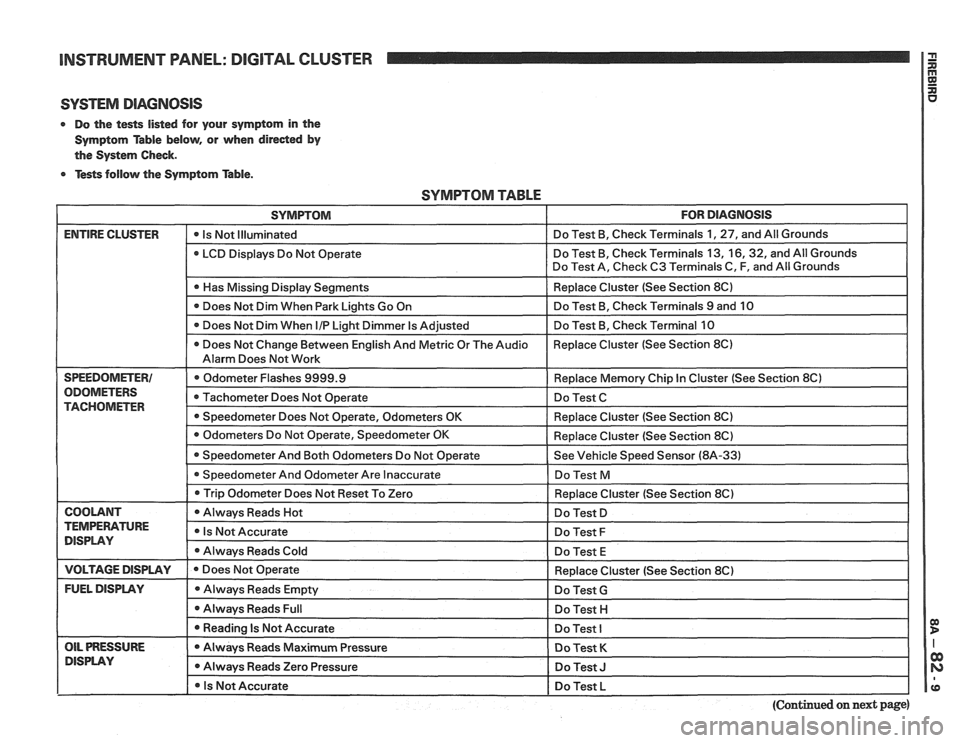
SYSTEM DIAGNOSIS
0 Do the tests listed for your symptom in the
Symptom Table below, or when
direded by
the System Check.
0 Tests follow the Symptom Table.
SYMPTOM TABLE
SYMPTOM FOR DIAGNOSIS
ENTIRE CLUSTER - -
0 Is Not Illuminated Do
Test B, Check Terminals 1, 27, and All Grounds
LCD Displays Do Not Operate Do
Test B, Check Terminals 13,
16,32, and All Grounds
Do Test A, Check C3 Terminals C, F, and All Grounds
I 0 Has Missing Display Senments I Replace Cluster (See Section 8C) I
Does Not Dim When Park Lights Go On Do
Test B, Check Terminals 9 and 10
Does Not Dim When
I/P Light Dimmer Is Adjusted Do
Test B, Check Terminal 10
0 Does Not Change Between English And Metric Or The Audio Replace
Cluster (See Section 8C)
Alarm Does Not Work
SPEEDOMETER1 Odometer Flashes 9999.9 Replace Memory Chip In Cluster (See Section 8Cl
ODOMETERS Tachometer Does Not Operate Do Test C TACHOMETER 0 Speedometer Does Not Operate, Odometers OK Replace Cluster (See Section 8C)
I 0 Trip Odometer Does ~otReset To Zero I Redace Cluster (See Section 8C) I
I COOLANT I 0 Always Reads Hot I Do Test D I
TEMPERATURE Is Not Accurate DISPLAY Do Test F
Always Reads Cold
Do Test E
I VOLTAGE DISPLAY I e Does Not Operate
FUEL DISPLAY Always Reads Empty
0 Always Reads Full
I 0 Reading Is Not Accurate - --
OIL PRESSURE Always Reads Maximum Pressure
DlSPLAV 0 Always Reads Zero Pressure
I 0 Is Not Accurate Replace
Cluster (See Section 8C)
Do Test
G
Do Test H I
Do Test I
Do Test K
Do Test J I
Do Test L I pp
(Continued on next page)
Page 1674 of 1825
MISCELLANEOUS ACCESSORIES 96-4
SCELLANEOUS ACCESSOR
General Description ................................. 9G-1
Rally Gages .................................................. 9G- 1
Tachometer ................................................. 9G- 1
Trip Odometer
............................................. 9G- 1
Electric Rear Window Defogger ................. 9G-2
Power Remote Control Rearview
Mirror ........................................................ 9G-2
Diagnosis .................................................... 9G-2
Rally Gages ............................................... 9G-2
Tachometer .................................... .... .... 9G-2
Electric Rear Window Defogger ................. 9G-2
Power Remote Control Rearview
Mirror ........................................................ 96-2
Dash and Console Mounted
Accessory Switches
................................. 9G-4
General Description .................................. 9G-4
Electronic Glare Control Mirror ................. 9G-4
On-Car Service ............................................. 9G-4
Rally Gages, Tach ....................................... 96-4.
Rear Window Defogger ............................ 96-4.
Power Remote Control Mirror .................... 9G-4
GENERAL BESCRIP"T0N
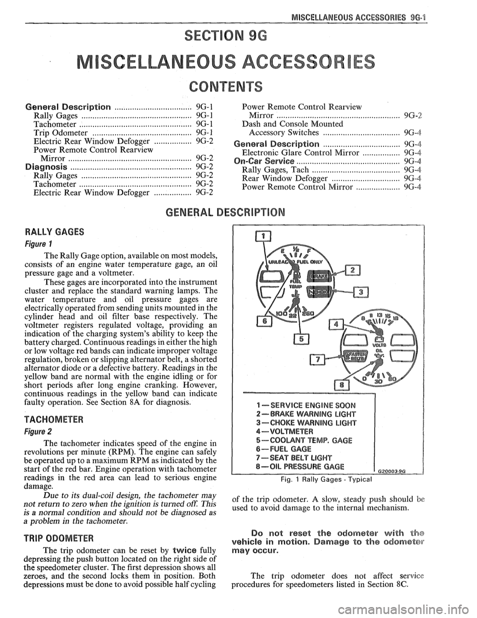
RALLY GAGES
Figure I
The Rally Gage option, available on most models,
consists of an engine water temperature gage, an oil
pressure gage and a voltmeter.
These gages are incorporated into the instrument
cluster and replace the standard warning lamps. The
water temperature and oil pressure gages are
electrically operated from sending units mounted in the
cylinder head and oil filter base respectively. The
voltmeter registers regulated voltage, providing an
indication of the charging system's ability to keep the
battery charged. Continuous readings in either the high
or low voltage red bands can indicate improper voltage
regulation, broken or slipping alternator belt,
a shorted
alternator diode
or a defective battery. Readings in the
yellow band are normal with the engine idling or for
short periods after long engine cranking. However,
continuous readings in the yellow band can indicate
faulty operation. See Section
8A for diagnosis.
TACHOMETER
Figure 2
The tachometer indicates speed of the engine in
revolutions per minute (RPM). The engine can safely
be operated up to a maximum RPM as indicated by the
start of the red bar. Engine operation with tachometer
readings in the red area can lead to serious engine
damage.
Due to its dual-coil design, the tachometer may
not return to zero when the ignition
is turned oft: This
is
a normal condition and should not be diagnosed as
a problem in the tachometer.
TRIP ODOMETER
The trip odometer can be reset by twice fully
depressing the push button located on the right side of
the speedometer cluster. The first depression shows all
zeroes, and the second locks them in position. Both
depressions must be done to avoid possible half cycling
I -SERVICE ENGINE SOON
2-BRAKE WARNING LIGHT
3-CHOKE WARNING LIGHT
4-VOLTMETER
5-COOUNT TEMP. GAGE
6-FUEL GAGE
7-SEAT BELT LIGHT
8-OIL PRESSURE GAGE G20003 9G
Fig. 1 Rally Gages - Typical
of the trip odometer. A slow, steady push should be
used to avoid damage to the internal mechanism.
Do not reset the odometer with the
vehicle in motion. Damage to the odometer
may occur.
The trip odometer does not affect service
procedures for speedometers listed in Section
8C.
Page 1733 of 1825
5H-20 DOORS - F STYLE
Removal and Installation
1.
Raise door window. Remove door trim panel and
inner panel water deflector.
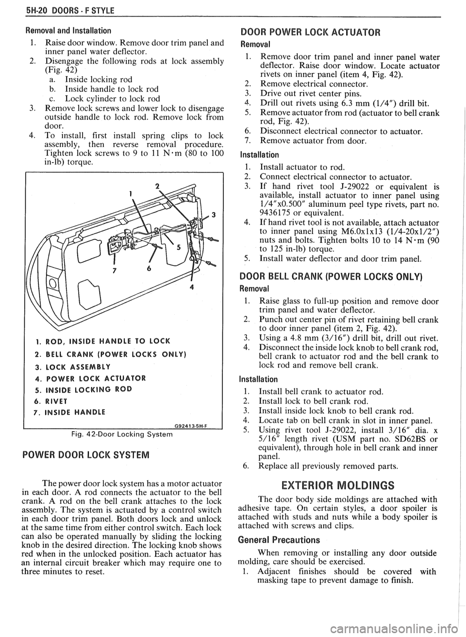
2. Disengage the following rods at lock assembly
(Fig. 42)
a. Inside locking rod
b. Inside handle to lock rod
c. Lock cylinder to lock rod
3. Remove lock screws and lower lock to disengage
outside handle to lock rod. Remove lock from
door.
4. To install, first install spring clips to lock
assembly, then reverse removal procedure.
Tighten lock screws to 9 to
11 Nem (80 to 100
in-lb) torque.
1. ROD, INSIDE HANDLE TO LOCK
2. BELL CRANK (POWER LOCKS ONLY)
3. LOCK ASSEMBLY
4. POWER LOCK ACTUATOR
4. INSIDE LOCKING ROD
6. RIVET
7. INSIDE HANDLE
G92413-5H-F
Fig. 42-Door Locking System
POWER DOOR LOCK SYSTEM
The power door lock system has a motor actuator
in each door.
A rod connects the actuator to the bell
crank. A rod on the bell crank attaches to the lock
assembly. The system is actuated by a control switch
in each door trim panel. Both doors lock and unlock
at the same time from either control switch. Each lock
can also be operated manually by sliding the locking
knob in the desired direction. The locking knob shows
red when in the unlocked position. Each actuator has
an internal circuit breaker which may require one to
three minutes to reset.
DOOR POWER LOCK ACTUATOR
Removal
Remove door trim panel and inner panel water
deflector. Raise door window. Locate actuator
rivets on inner panel (item
4, Fig. 42).
Remove electrical connector.
Drive out rivet center pins.
Drill out rivets using 6.3 mm
(1/4") drill bit.
Remove actuator from rod (actuator to bell crank
rod, Fig. 42).
Disconnect electrical connector to actuator.
Remove actuator from door.
Installation
1. Install actuator to rod.
2. Connect electrical connector to actuator.
3. If hand rivet tool J-29022 or equivalent is
available, install actuator to inner panel using
1/4"x0.500" aluminum peel type rivets, part no.
9436175 or equivalent.
4. If hand rivet tool is not available, attach actuator
to inner panel using
M6.0~1~13 (1/4-20x1/2")
nuts and bolts. Tighten bolts 10 to 14 N-m (90
to 125 in-lb) torque.
5. Install water deflector and door trim panel.
DOOR BELL CRANK (POWER LOCKS ONLY)
Removal
1.
Raise glass to full-up position and remove door
trim panel and water deflector.
2. Punch out center pin of rivet retaining bell crank
to door inner panel (item 2, Fig. 42).
3. Using a
4.8 mm (3/16") drill bit, drill out rivet.
4. Disconnect the inside
lock knob to bell crank rod,
bell crank to actuator rod and the bell crank to
lock rod and remove bell crank.
Installation
1.
Install bell crank to actuator rod.
2. Install lock to bell crank rod.
3. Install inside lock knob to bell crank rod.
4. Locate tab on bell crank in slot in inner panel.
5. Using rivet tool J-29022, install 3/16" dia. x
5/16" length rivet (USM part no.
SD62BS or
equivalent), through hole in bell crank and inner
panel.
6. Replace all previously removed parts.
EXTERIOR MOLDINGS
The door body side moldings are attached with
adhesive tape. On certain styles, a door spoiler is
attached with studs and nuts while a body spoiler is
attached with screws and clips.
General Precautions
When removing or installing any door outside
molding, care should be exercised.
1. Adjacent finishes should be covered with
masking tape to prevent damage to finish.