1988 PONTIAC FIERO weight
[x] Cancel search: weightPage 59 of 1825
"18-16 AIR CONDITIONING
B . Accumulator dehydrator
@ Add 105 ml (3.5 fl. 02.) to new
accumulator
C. Evaporator
@ Add 90 ml (3 fl. oz.) oil
D. Condenser
@ Add 30 ml (1 fl. 02.) oil
Refrigerant oil loss due to a large leak
If the refrigerant charge is aburptly lost due to a
large refrigerant leak, approximately 90
ml (3 fl. oz.)
of refrigerant oil will be
carried out of the system sus-
pended in the refrigerant. Any failure that caused an
abrupt refrigerant discharge will experience this oil
loss. Failures that allow the refrigerant to seep or
bleed off over time do not experience this oil loss.
Upon replacement of a component which
caused a large refrigerant leak, add 90 ml(3
fl. oz.) of
new 525 viscosity refrigerant oil plus the required
amount of oil for the particular component (as out-
lined above).
Add the oil directly to the replaced component if
possible. If the oil cannot easily be added to the
replaced part, add the oil to the accumulator.
Evacuating and Charging the A/C System
If the system has been opened for any repair, or
the Refrigerant-12 charge lost, the system must be
evacuated prior to charging.
Evacuating and charging is a combined proce-
dure, and all gauge lines must be purged with R-12
prior to charging.
There are three evacuate and charge procedures.
1.
J 23500-01 Charging Station Method
2. Disposable Can Method 3. Drum Method
NOTICE: Under no circumstances should alco-
hol be used in the system in an attempt to remove
moisture. Damage to the system components
could occur.
Gauge Calibration
Prior to evacuation, check the low-pressure
gauge for proper calibration and determine if vacuum
system is operating properly.
With the gauge disconnected from the refrigera-
tion system, be sure that the pointer indicates to the
center of
"0". Lightly tap gauge a few times to be sure
pointer is not sticking. If necessary, calibrate as
follows:
1. Remove cover from gauge.
2. Holding gauge pointer adjusting screw firmly
with one hand, carefully force pointer in the
proper direction to position pointer at the
"0"
position. Tap gauge a few times to be sure
pointer is not sticking. Replace gauge cover.
Vacuum System Check
Before connecting vacuum pump to the A/C
system, run pump connected to the low-pressure
gauge to determine the vacuum pump capability. If
the vacuum system is unable to reach
7 1 1.2-736.6mm
(28"-29") or more vacuum, the system should be
checked for leaks. If no leaks are found, the vacuum
pump may require repair.
5-23580-81 OR EQUIVALENT CHARGING
STATION METHOD.
Follow charging instructions provided with the
5-23500-01 Charging Station or equivalent in use with
the following exceptions:
1. Do
not connect the high-pressure line to the air
conditioning system.
2. Keep the high-pressure valve on the charging
station closed at all times.
3.
Perform the entire evacuate and charge proce-
dure through the accumulator low-side pressure service fitting.
4. Following these procedures will prevent acci-
dental high-side vehicle system pressure being
subjected to the charging station in the event an
error is made in valve sequence during compres-
sor operation to pull in the Refrigerant-12
charge.
DISPOSABLE CAN OR REFRIGERANT
DRUM METHOD.
If the Refrigerant-12 drum is used, place it on a
scale and note the total weight before charging. Watch
the scale during charging to determine the amount of
R-12 used.
If disposable
420ml (14 ounce) R-12 cans are
used, close the tapping valve and then attach
can(s)
following instructions included with the tapping valve
or tapping manifold adapter.
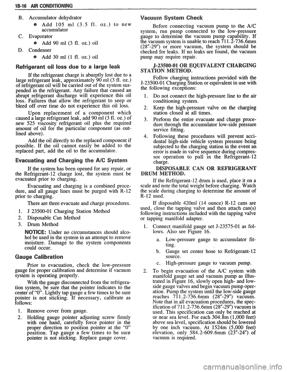
1. Connect manifold gauge set 5-23575-01 as fol-
lows. Also see Figure 16.
a. Eow-pressure gauge to accumulator fit-
ting.
b. Gauge set center hosk to Refrigerant-12
source.
c. High-pressure gauge to vacuum pump.
2. To begin evacuation of the
A/C system with
manifold gauge set and vacuum pump as illus-
trated in Figure 16, slowly open
high- and low-
side gauge valves and begin vacuum pump oper-
ation. Pump the system until the low-side gauge
reaches 7 1
1.2-736.6mm (28"-29") vacuum.
Note that in all evacuation procedures, the spec-
ification of 7 1
1.2-736.6mm (28"-29") vacuum is
used. This specification can only be reached at
or near sea level. For each
304.8m (1,000 feet)
above sea level, specification should be lowered
by one inch vacuum. At
1524m (5,000 feet)
elevation, only
584.2-609.6mm (23"-24") of
vacuum is required.
Page 102 of 1825
BUMPERS 28-1
SECTION 2B
BUMPERS
NOTICE: These fasteners are important attaching parts in that they could affect the performance of vital parts and
systems,
andlor could result in major repair expense. They must be replaced with one of the same part number or with an
equivalent
part if replacement becomes necessary. Do not use a replacement part of lesser quality or substitute design.
Torque values must be used as specified during reassembly to assure proper retention of all parts. There is to be no
welding as it may result in extensive damage and weakening of the metal.
NOTICE: The anti-theft label on some major sheet metal, engines, and transmissions must be masked prior to
painting, rustproofing, undercoating, etc. The mask MUST be removed following the above operations. Failure to keep
the label clean and readable may result in liability for violation of Federal Vehicle Theft Prevention Standard, and subject
the vehicle owner to possible suspicion that the part was stolen.
CONTENTS
General Description ................................ 2B-1 On-Vehicle Service ..................................... 2B-4
........................................... ..................... Service Procedures .. ........... 2B- 1 Specifications 2B-5
GENERAL DESCRIPWIBN
The bumpers on all Pontiac automobiles are remover.
Install new tape (double-coated neoprene
designed so that the vehicle can withstand a collision foam type)
to the back side of the rub strip.
into a fixed barrier at
5 mph. After absorbing the
energy of a collision, the bumpers restore themselves After
rub strip is installed, roll along entire
to their original position. surface with a roller
in order to insure a good bond.
The front and rear bumper fascias are made of
urethane. Urethane will withstand minor impact and
return to its original shape. Some front bumper fascias
are integral with the front end panel.
Some models use both steel and aluminum
bumper reinforcements. Usage is based on
EPA weight
class requirements.
BUMPER FASCIA RUB STRIPS
Some front and rear fascia rub strips are made of
a shiny plastic material. If a rub strip of this type loses
its lustre, the original shine can be restored by using
GM Plastic Cleaner or its equivalent. Follow directions
on the label.
SERVICE PROCEDURES
RUB STRIPS
Remove and Replace
Some plastic rub strips have an adhesive tape
backing (similar to a body side molding) and some have
studs or retaining tabs. In order to properly remove the
adhesive tape and avoid paint damage to the fascia, use
either a release agent or a heat lamp to soften the bond
of the adhesive tape to the fascia. In some cases, it will
be necessary to replace the rub strip with a new rub
strip instead of reusing the old one.
If the old rub strip is salvagable, remove all tape
from the back side of the rub strip as previously
described. Wipe strip clean with a wax and adhesive
FRONT BUMPER FASCIA (FRONT END PANEL)
Removal
Place a jack stand under fascia assembly before
removing bolts to prevent it from dropping down when
fascia attaching bolts are removed. Fascia will pivot on
the opposite end when one end is disconnected. Do not
rotate energy absorber any more than necessary to
align mounting holes.
1. Remove fascia attaching bolts and fascia to
fender attaching screws on right and left side, and
remove fascia and spacers.
2. If energy absorber is to be replaced, remove the
bolts and nuts from the front of the unit and the
nut from the stud at the rear.
Installation
1. Install energy absorber if removed.
2. Support fascia during installation to prevent
rotation of energy absorbers.
3. Install spacers and bolts at fascia to energy
absorber brackets.
4. Install fascia to fender attaching screws.
5. Check for proper clearance.
6. If adjustment is required to align fascia, loosen
energy absorber mounting bolts and position as
required (holes are slotted). Adjustment side to
side can be made by loosening fascia bracket
bolts. Torque all bolts and nuts. (See
Specifications.)
Page 143 of 1825
3-18 STEERING, SUSPENSION, TIRES AND WHEELS DIAGNOSIS
VIBRATION COMPLANT TIRE-WHEEL-HUB-AXLE RELATED
Vibrations that are tire or wheel induced can be caused
by two factors: imbalance or
runout. Low-speed vibrations, those less than 40 mph, are
usually runout related. Highway speed vibrations, those
above 40 mph, can be caused by either imbalance or runout. Prior to performing any work, always road test the car
and perform a careful visual inspection for:
- Obvious tire and wheel runout. - Obvious drive 'axle or propeller shaft runout. - Proper inflation pressure. - Wrong trim height. - Bent wheels. - Debris build-up on the tire or wheel. - Loose or missing wheel weights or wheel nuts. - Irregular or excessive tire wear. - Proper tire bead seating on rim. - Damaged tires, such as tread distortions,
separations, or bulges from impact damage. Slight sidewall indentations are normal and will not affect
ride quality.
Balance is the easiest procedure to perform and should,
therefore, be done fist if the vibration occurs at highway
speeds.
An off-car two-plane dynamic balance should first
be performed. This will correct any imbalance in the tire and
wheel assembly.
An oncar fiish balance may also be required. This will correct any brake drum, rotor, or wheel cover imbalance.
Follow the balancing procedures outlined in Section 3E. If balance does not correct the highway speed vibration,
or if the vibration is at low speeds, runout is the probable
cause. Runout can be caused by the tire, wheel, or the way
the wheel attaches to the car. The following procedure
should be used
: A. If runout is suspected, the free runout of the tire
and wheel assembly should first be measured on the car. A
dial indicator with a roller wheel is preferable, but a dial
indicator with button end may be used. Lateral
runout (side
to side) should be measured on the tire's sidewall as close to
the tread shoulder as possible. Radial
runout (up and down)
should be measured on the center tread rib. Some tread
designs may require tightly wrapping a piece of tape around
the center tread circumference for better dial indicator
contact. For measuring wheel
runout follow the "Measuring
Wheel Runout" procedure in Section 3E. Whether measuring
radial or lateral runout, disregard any instantaneous indicator
needle jumps due to sidewall depressions, tread blocks, etc.
Record the total indicator reading, and the location of the
high point of
runout. The,,total tire and wheel oncar runout should be less than ,060 , if either measurement exceeds ,060"~ proceed to Step B.
B. If
the oncy radial or lateral runout measured in
Step A exceeds .060 , mount the tire and wheel assembly on
a dynamic balance machine and again measure the amount of runout. Locate on the machine by the wheel's inside center
pilot hole. Using the same procedure as in Step A, record the
amount of tire and wheel
runout and its high point Location.
Next, measure wheel runout, see Section 3E. If the wheel
exceeds specifications replace the ~heel.,~If the tire and wheel
radial or lateral runout exceeds .050 at the tire tread,
proceed to Step C.
C. If the off-car tire and wheel radial or lateral runout measured in Step 18 exceeds .050", match mount the high radial runout point of tire to low radial runout point of
wheel. Weinflate, mount on the dynamic balance machine,
and again measure and record the radial and lateral runout and its location, as done in Step B. In many cases, match
mounting the tire on the wheel will bring the assembly's
runout into the acceptable range of less than .050". D. If the runout of the tire and wheel assembly is
within limits when measured off the car, yet exceeds the
limits when measured on the car, the attachment of the tire
and wheel assembly to the hub is the probable cause. Rotate
the assembly two wheel studs and recheck the
runout. Several positions may have to be tried to find the best
location.
E. If the assembly runout cannot be reduced to an
acceptable level, remove the tire and wheel assembly and
measure wheel stud
runout with a dial indicator. Zero
the dial indicator button on one stud. Lift button gently
off stud and rotate flange to position next stud against
dial indicator button. Record the
runout on all studs. Dial indicator should read zero when repositioned on first stud
that was checked. If runout exceeds .030", the hub or axle
shaft should be replaced.
Whenever a tire is rotated on the wheel, or a tire or
wheel is replaced, the assembly must be rebalanced.
In addition to balance and tire and wheel free
runout, tire stiffness variation (loaded radial runout) can also cause
a vibration. However, this is impossible to measure without
a TPD (Tire Problem Detector) or a loaded radial
runout buffer.
The TPD is a roller drum that slowly rotates the tire
while under load and mounted on the car. Tire stiffness
variation causes wheel spindle movement which can be
measured.
The loaded radial
runout buffer is a more automated
machine that slowly rotates the tire and wheel off the car
under load with a roller drum and measures the tire's
stiffness variation. It will then "match" the tire to the wheel
by buffing off small amounts of rubber from the outer tread
rows at the stiff spot. This procedure is usually effective,
especially when used
as a measuring device and for fine
buffing only.
The
TPD and loaded radial runout buffer are two
methods that will measure or correct tire stiffness variation,
tire
runout, and wheel runout at the same time. However,
because such equipment is not always available, and both
have their disadvantages, the more basic procedure of
measuring free
runout with a dial indicator, as previously
detailed, is usually more practical. The free runout of the
tire will usually correspond with the tire's stiff spot.
The substitution method of vibration diagnosis can also
be used. Install
a known good set of tire and wheel
assemblies. If these correct the vibration, the original
assemblies should be reinstalled one at
a time until the
vibration returns. This will point out the tire with excess
stiffness variation.
Tire stiffness variation will be higher or lower depending
on the direction of tire rotation.
Fig. 20 Vibration Complaint Chart (2 of 2)
Page 146 of 1825
STEERING, SUSPENSION. TIRES AND WHEELS DIAGNOSIS 3-21
TRIM WEIGHTS (@ CURB WEIGHT) I
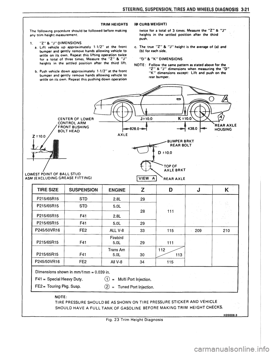
The follow~ng procedure should be followed before making
any trim height measurement.
1.
"2" & "J" DIMENSIONS a. Lift vehicle up approximately 1-112" at the front
bumper and gently remove hands allowing vehicle to
settle on its own. Repeat this lifting operation twice
for
a total of three times. Measure the "2" & "J" heights in the settled position after the third lift.
b. Push vehicle down approximately
1.1/2"at the front
bumper and gently remove hands allowing vehicle to
settle on its own. Repeat this pushing down operation twice for
a total
of 3 times. Mewre the "Z" & "J" heights in the settled position after the third
push.
c. The true
"2" L "J" height is the averlge of (a) and (b) for each side.
"0" L "K" DIMENSIONS
NOTE
: Follow the same pattern cn stated above for the "Z" & "J" dimensions when measuring the "0" "K" dimensions except: Lift and push on the
rear bumper.
CENTER OF
LOWE CONTROL ARM 'FRONT BUSHING BOLT HEAD k828.0-t REAR AXLE
Z '10.0 / AXLE
BUMPER BRKT
REAR BOLT
ASM (EXCLUDING GREASE FITTING)
I Dimensions shown in mmll mm = 0.039 in. I
F41 = Special Heavy Duty. = Multi Port Injection.
FE2 = Touring Pkg. Susp.
NOTE:
TIRE PRESSURE
SHOULDBE AS SHOWN ON TIRE PRESSURE STICKER AND VEHICLE
SHOULD HAVE A
FULLTANK OF GASOLINE BEFORE MAKING TRIM HEIGHT CHECKS.
I Fig. 23 Trim Height Diagnosis
Page 149 of 1825
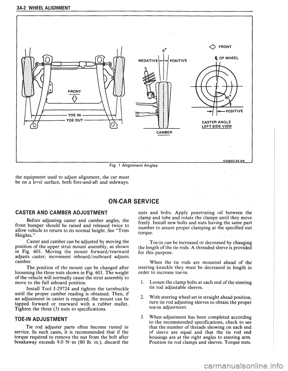
3A-2 WHEEL ALIGNMENT
0 FRONT
& OF WHEEL
CASTER ANGLE
LEFT SIDE
VIEW
CAMBER
I
Fig. 1 Alignment Angles
the equipment used to adjust alignment, the car must
be on a
level surface, both fore-and-aft and sideways.
ON-CAR SERVICE
CASTER AND CAMBER ADJUSTMENT nuts and bolts. Apply penetrating oil between the
clamp and tube and rotate the clamps until they move
Before adjusting caster and camber the freely. Install new bolts and nuts having the same part front be 'aised and twice to number to assure proper at the specified nut allow vehicle to return to its normal height. See "Trim torque. Heights."
Caster and camber can be adjusted by moving the
position of the upper strut mount assembly, as shown
in Fig. 601. Moving
the mount forward/rearward
adjusts caster; 'movement inboard/outboard adjusts
camber.
The position of the mount can be changed after
loosening the three nuts shown in Fig.
601. The weight
of the vehicle will normally cause the strut assembly to
move to the full inboard position.
Install Tool
5-29724 and tighten the turnbuckle
until the proper camber reading is obtained. Then, if
an adjustment in caster is required, the mount can be
tapped forward or rearward with a rubber mallet.
Tighten the three
(3) nuts to specifications.
TOE-IN ADJUSTMENT
Toe-in can be increased or decreased by changing
the length of the tie rods.
A threaded sleeve is provided
for this purpose.
When the tie rods are mounted ahead of the
steering knuckle they must be decreased in length in
order to increase toe-in.
1. Loosen the clamp bolts at each end of the steering
tie rod adjustable sleeves.
2. With steering wheel set in straight ahead position,
turn tie rod adjusting sleeves to obtain the proper
toe-in
adjustrne~t.
3. When adjustment has been completed according
to the recommended snecifications. check to see
Tie rod adjuster parts often become rusted in
that the number of thrkads showing on each end
service. In such cases, it is recommended that if the
of sleeve are equal and that the tie rod end
torque required to remove the nut from the bolt after housings are at the right angles to steering arm.
breakaway exceeds 9.0
Nam (80 lb. in.), discard the
Position tie rod clamps and sleeves. Torque nuts.
Page 222 of 1825
REAR SUSPENSION 30.1
SECTION 3D
REAR SUSPENS
NOTICE: All rear suspension fasteners are important attaching parts in that they could affect the
performance of vital parts and systems, and/or could result in major repair expense. They must be replaced with
one of the same part number or with an equivalent part if replacement becomes necessary. Do not use
a
replacement part of lesser quality or substitute design. Torque values must be used as specified during reassembly
to assure proper retention of all parts. There is to be no welding as it may result in extensive damage and weakening
of the metal.
CONTENTS
General Information ................................ 3D- 1 Rear Lower Control Arm ............................ 3D-4
Qn-Car Service ............................ .. .......... 3D- 1 Bushing (Rear Lower Control Arm) ........... 3D-4
Shock Absorbers ........................................ 3D- 1 Torque Arm .............................................. 3D-5
Coil Springs and Insulators ......................... 3D- 1 Rear Stabilizer Shaft .................................. 3D-6
Track Bar ................................................... 3D-3 Bumper (Rubber) ....................................... 3D-6
Track Bar Brace ................... .. ................. 3D-3 Torque Specifications .................................. 3D-9
GENERAL INFORMATION
The rear axle assembly is attached to the vehicle
through a link type suspension system. The axle
housing is connected to the body by two lower control
arms and a track bar. A single torque arm is used in
place of upper control arms. It is rigidly mounted to the
rear axle housing at the rear and through a rubber
bushing to the transmission at the front. Coil springs
are used to support the weight of the car, and ride
control is provided by shock absorbers mounted to the
rear of the axle housing. A stabilizer shaft is optional.
The shock absorbers are mounted at the bottom
with a bolt and nut to brackets welded to the axle
housing, and at the top to the reinforced body area with
a nut. The only service the shock absorbers require is
replacement if they
have lost tllcir resistance, are
danaged, or are leaking flldd.
ON-CAR SERVICE
SI-IOCK ABSORBERS
Fig. 602
Remove or Disconnect
1. Hoist car and support rear axle.
2. From above, pull back carpeting and remove
shock absorber upper mounting nut.
NOTICE: Axle assembly must be supported
before removing upper shock absorber nut to avoid
possible damage to brake lines, track bar and prop
shaft.
3. Loosen and remove shock absorber lower
mounting nut from shock absorber. Remove
shock.
Install or Connect
NOTICE: See NOTICE on Page 3D-1 of this
section.
1. Position shock absorber through body mounting
hole and loosely install the lower shock absorber
mounting nut.
2. From above, install the upper shock absorber
retainer and nut. Torque nut.
3. Torque lower shock absorber nut.
4. Remove rear axle support and lower car.
COIL SPRINGS AND INSULATORS
Fig. 603
Remove or Disconnect
1. Hoist car on non twin post-type hoist and support
rear axle assembly with an adjustable lifting
device.
2. Track bar mounting bolt at axle assembly.
Loosen track bar bolt at body brace.
3. Rear brake hose clip at underbody to allow
additional axle drop.
4. Right and left shock absorber lower attaching
nuts.
5. Carefully lower rear axle and remove spring(s)
and or insulator(s).
NOTICE: DO NOT suspend rear axle by brake
hose. Damage to hose could result.
Install or Connect
NOTICE: See NOTICE on Page 3D-1 of this
section.
Page 224 of 1825
REAR SUSPENSION 30-3
1. Position springs and insulators in spring seats and
raise rear axle until rear axle supports weight of
vehicle at normal curb height position.
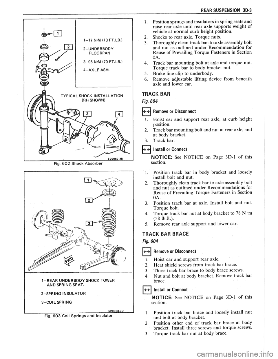
2. Shocks to rear axle. Torque nuts. 1-17 N.M (13 FT.LB.1 3. Thoroughly clean track bar-to-axle assembly bolt
2-UNDERBODY and nut as outlined under Recommendation for
Reuse of Prevailing Torque Fasteners in Section
3-95 NeM (70 FT.LB.) 4. Track bar mounting bolt at axle and torque nut.
4-AXLE ASM. Torque track bar to body bracket nut.
5. Brake line clip to underbody.
6. Remove adjustable lifting device from beneath
axle and lower car.
TYPICAL SHOCK INSTALLATION TRACK BAR (RH SHOWN)
Remove or Disconnect
at body bracket.
3. Track bar.
Install or Connect
NOTICE: See NOTICE on Page 3D-1 of this
1. Position track bar in body bracket and loosely
install bolt and nut.
2. Thoroughly clean track bar to axle assembly bolt
and nut as outlined under Recommendations for
Reuse of Prevailing Torque Fasteners in Section
3. Position track bar at axle. Install bolt and nut.
4. Torque track bar nut at body bracket to 78 Nem
5. Remove rear axle support and lower car.
TRACK BAR BRACE
1. Hoist car and support rear axle.
2. Heat shield screws from track bar brace.
3. Three track bar brace to body brace screws.
4. Nut and bolt at body bracket. Remove track bar 1-REAR UNDERBODY SHOCK TOWER
AND SPRING SEAT.
2-SPRING INSULATOR
NOTICE: See NOTICE on Page 3D-1 of this 3-COIL SPRING
1. Position track bar brace and loosely install nut Fig. 603 Coil Springs and Insulator and bolt at body bracket.
2. Position other end of track bar brace at body
bracket. Install three screws and torque screws.
3. Torque track bar nut at body brace.
Page 227 of 1825
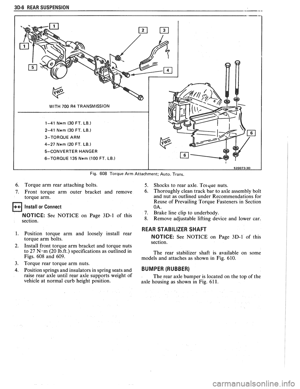
30-8 WEAR SUSPENSION
WITH 700 R4 TRANSMISSION
1-41 Nern (30 FT.
LB.)
2-41 Nern (30 FT. LB.)
3-TORQUE ARM
4-27 Nern
(20 FT. LB.)
5-CONVERTER HANGER
6-TORQUE 135
Nern (100 FT. LB.)
Fig. 608 Torque Arm Attachment; Auto. Trans.
6. Torque arm rear attaching bolts. 5. Shocks to rear axle. Toique nuts.
7. Front torque arm outer bracket and remove
6. Thoroughly clean track bar to axle assembly bolt
torque arm. and nut
as outlined under Recommendations for
Reuse of Prevailing Torque Fasteners in Section
Install or Connect OA.
7. Brake line clip to underbody. On Page 3D-1 of this 8. Remove adjustable lifting device and lower car.
section.
1. Position torque arm and loosely install rear
torque arm bolts.
2. Install front torque arm bracket and torque nuts
to 27
N.m (20 1b.ft.) specifications as outlined in
Figs.
608 and 609.
3.
Torque rear torque arm nuts.
4. Position springs and insulators in spring seats and
raise rear axle until rear axle supports weight of
vehicle at normal curb height position.
REAR STABILIZER SHAFT
NOTICE: See NOTICE on Page 3D-1 of this
section.
The rear stabilizer shaft is available on some
models and attaches as shown in Fig.
610.
BUMPER (RUBBER)
The rear axle bumper is located on the top of the
axle housing as shown in Fig.
61 1.