1988 PONTIAC FIERO weight
[x] Cancel search: weightPage 1683 of 1825

1 H-2 GENERAL INFORMATION - F STYLE
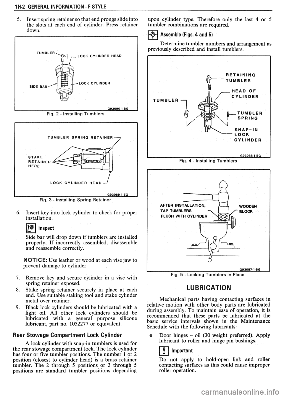
5. Insert spring retainer so that end prongs slide into
upon cylinder type. Therefore only the last 4 or 5
the slots at each end of cylinder. Press retainer
tumbler combinations are required.
down.
TUMBLER \m , LOCK CYLINDER HEAD
SIDE BAR LOCK CYLINDER
Fig.
2 - Installing Tumblers
TUMBLER SPRING RETAINER
LOCK CYLINDER HEAD
Fig.
3 - Installing Spring Retainer
6. Insert key into lock cylinder to check for proper
installation.
Inspect
Side bar will drop down if tumblers are installed
properly, If incorrectly assembled, disassemble
and reassemble correctly.
NOTICE: Use leather or wood at each vise jaw to
prevent damage to cylinder.
7. Remove key and secure cylinder in a vise with
spring retainer exposed.
8. Stake spring retainer securely in place at each
end. Use suitable staking tool and stake cylinder
metal over retainer.
9. Black lock cylinders should be lubricated with a
light oil. All other lock cylinders should be
lubricated with a general purpose silicone
lubricant, part no. 1052277 or equivalent.
Assemble (Figs. 4 and 5)
Determine tumbler numbers and arrangement as
previously described and install tumblers,
TUMBLER
I CYLINDER I
Fig. 4 - Installing Tumblers
AFTER INS WOODEN
TAP TUMBLERS BLOCK
FLUSH
WITH CYLINDER
Fig. 5 - Locking Tumblers in Place
LUBRICATION
Mechanical parts having contacting surfaces in
relative motion with other body parts are lubricated
during assembly. To maintain ease of operation, it is
recommended that these parts be lubricated at the
basic service intervals shown in the Maintenance
Schedule with the following lubricants:
Rear Stowage Compartment Lock Cylinder Door hinges - oil (30 weight preferred). Apply
A lock cylinder with snap-in tumblers is used for lubricant
to roller and hinge pin bushings.
the rear stowage compartment lock. The lock cylinder
Important has four or five tumbler positions. The number 1 or 2
position (closest to cylinder head) is a brass retainer Do
not apply to hold-open link and roller
tumbler. The
2 through 5 positions or 3 through 5 contacting
surfaces as this could cause improper
positions are standard tumbler positions depending roller operation.
Page 1732 of 1825

DOORS - F STYLE 5H-99
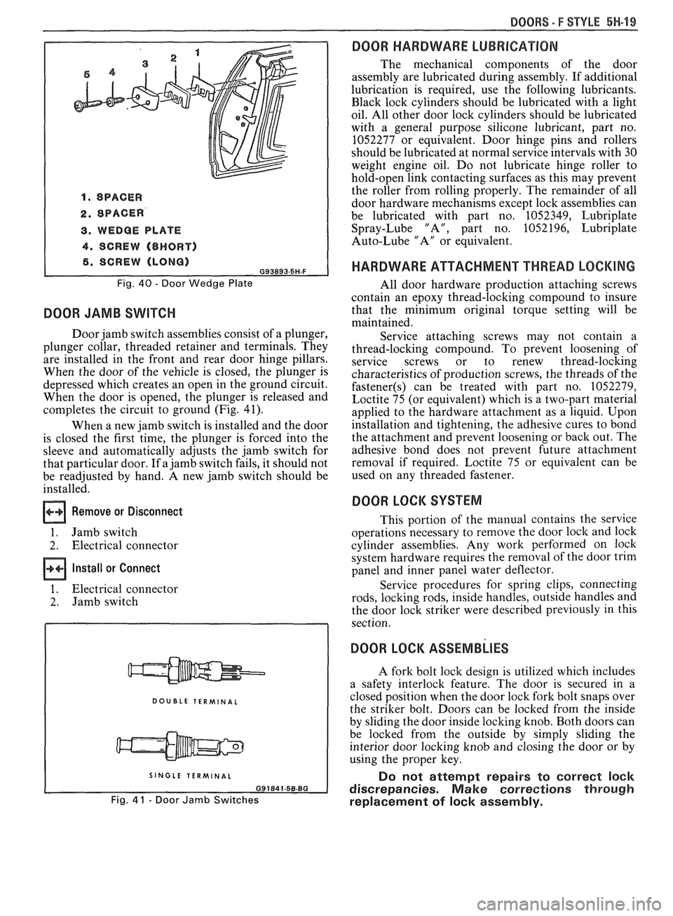
1. SPACER
2. SPACER
3. WEDGE PLATE
4. SCREW (8HORT)
6. SCREW (LONG) G93893.5H-F
Fig. 40 - Door Wedge Plate
DOOR JAMB SWITCH
Door jamb switch assemblies consist of a plunger,
plunger collar, threaded retainer and terminals. They
are installed in the front and rear door hinge pillars.
When the door of the vehicle is closed, the plunger is
depressed which creates an open in the ground circuit.
When the door is opened, the plunger is released and
completes the circuit to ground (Fig. 41).
When a new jamb switch is installed and the door
is closed the first time, the plunger is forced into the
sleeve and automatically adjusts the jamb switch for
that particular door. If a jamb switch fails, it should not
be readjusted by hand. A new jamb switch should be
installed.
Remove or Disconnect
1. Jamb switch
2. Electrical connector
Install or Connect
1. Electrical connector
2. Jamb switch
DOUBLE TERMINAL
I SINGLE TERMINAL I
Fig. 4 1 - Door Jamb Switches
DOOR HARDWARE LUBRICATION
The mechanical components of the door
assembly are lubricated during assembly. If additional
lubrication is required, use the following lubricants.
Black lock cylinders should be lubricated with a light
oil. All other door lock cylinders should be lubricated
with a general purpose silicone lubricant, part no.
1052277 or equivalent. Door hinge pins and rollers
should be lubricated at normal service intervals with 30
weight engine oil. Do not lubricate hinge roller to
hold-open link contacting surfaces as this may prevent
the roller from rolling properly. The remainder of all
door hardware mechanisms except lock assemblies can
be lubricated with part no. 1052349, Lubriplate
Spray-Lube "A", part no. 1052196, Lubriplate
Auto-Lube "A" or equivalent.
HARDWARE ATTACHMENT THREAD LOCKING
All door hardware production attaching screws
contain an epoxy thread-locking compound to insure
that the minimum original torque setting will be
maintained.
Service attaching screws may not contain a
thread-locking compound. To prevent loosening of
service screws or to renew thread-locking
characteristics of production screws, the threads of the
fastener(s) can be treated with part no. 1052279,
Loctite 75 (or equivalent) which is a two-part material
applied to the hardware attachment as a liquid. Upon
installation and tightening, the adhesive cures to bond
the attachment and prevent loosening or back out. The
adhesive bond does not prevent future attachment
removal if required. Loctite 75 or equivalent can be
used on any threaded fastener.
DOOR LOCK SYSTEM
This portion of the manual contains the service
operations necessary to remove the door lock and lock
cylinder assemblies. Any work performed on lock
system hardware requires the removal of the door trim
panel and inner panel water deflector.
Service procedures for spring clips, connecting
rods, locking rods, inside handles, outside handles and
the door lock striker were described previously in this
section.
DOOR LOCK ASSEMBLIES
A fork bolt lock design is utilized which includes
a safety interlock feature. The door is secured in a
closed position when the door lock fork bolt snaps over
the striker bolt. Doors can be locked from the inside
by sliding the door inside locking knob. Both doors can
be locked from the outside by simply sliding the
interior door locking knob and closing the door or by
using the proper key.
Do not attempt repairs to correct lock
discrepancies. Make corrections through
replacement of lock assembly.
Page 1767 of 1825

8H.8 ROOF - F STYLE
THREE PIECE CENTER
UPPER POLYCARBONATE FINISHING MOLDING GLASS (1 BAR)
CHANNEL 1
VERTICAL WALL
SECTION A-A
MOLDING ASSEMBLY
A ATTACHING SCREWS
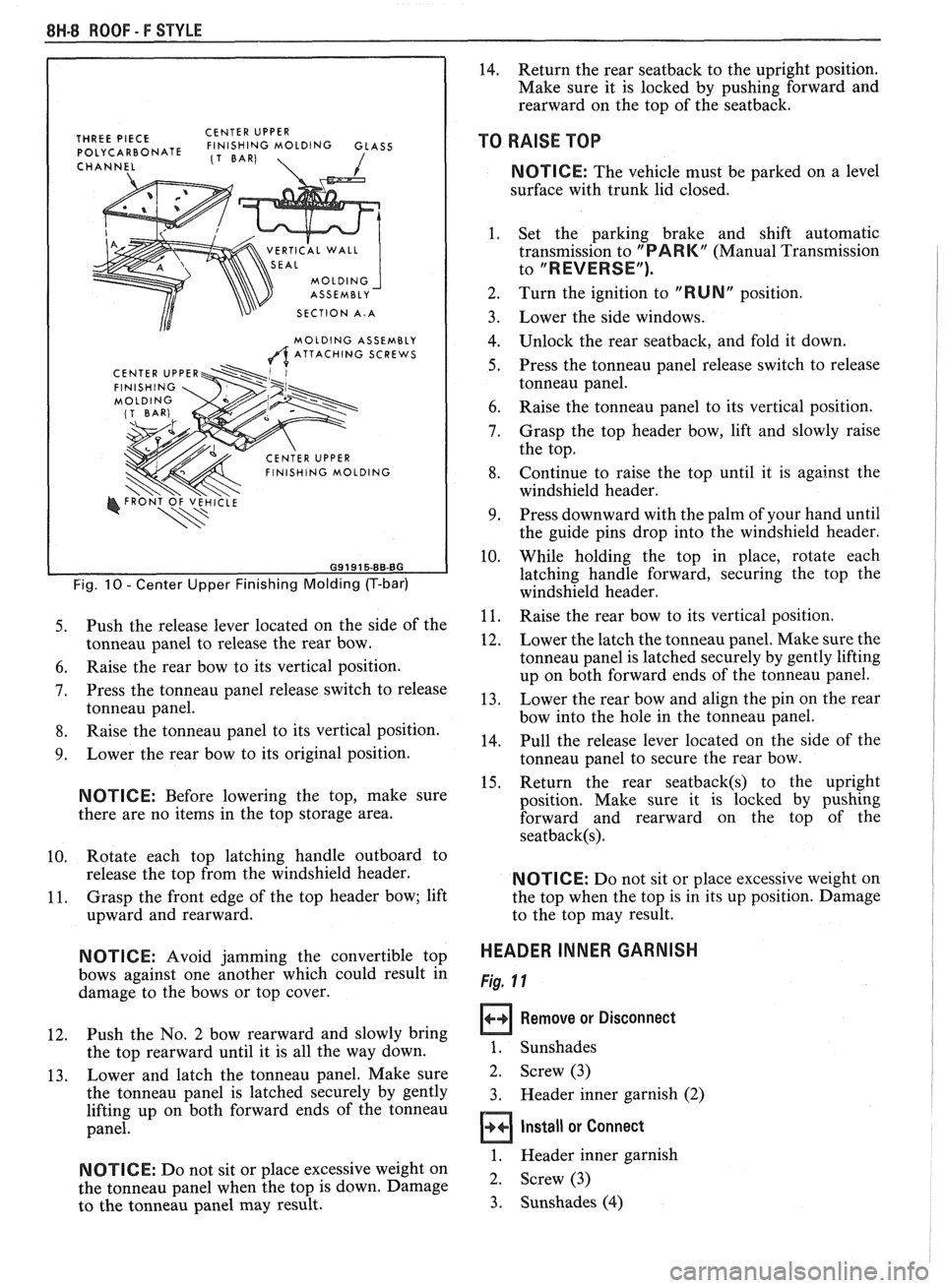
Fig. 10 - Center Upper Finishing Molding (T-bar)
5. Push the release lever located on the side of the
tonneau panel to release the rear bow.
6. Raise the rear bow to its vertical position.
7. Press the tonneau panel release switch to release
tonneau panel.
8. Raise the tonneau panel to its vertical position.
9. Lower the rear bow to its original position.
NOTICE: Before lowering the top, make sure
there are no items in the top storage area.
10. Rotate
each top latching handle outboard to
release the top from the windshield header.
11. Grasp
the front edge of the top header bow; lift
upward and rearward.
N OTI C E: Avoid jamming the convertible top
bows against one another which could result in
damage to the bows or top cover.
12. Push the
No. 2 bow rearward and slowly bring
the top rearward until it is all the way down.
13. Lower
and latch the tonneau panel. Make sure
the tonneau panel is latched securely by gently
lifting up on both forward ends of the tonneau
panel.
NOTICE: Do not sit or place excessive weight on
the tonneau panel when the top is down. Damage
to the tonneau panel may result.
14. Return the rear seatback to the upright position.
Make sure it is locked by pushing forward and
rearward on the top of the seatback.
TO RAISE TOP
NOTICE: The vehicle must be parked on a level
surface with trunk lid closed.
1. Set the parking brake and shift automatic
transmission to
"PARK" (Manual Transmission
to
"REVERSE").
2. Turn the ignition to "RUN" position.
Lower the side windows.
Unlock the rear seatback, and fold it down.
Press the tonneau panel release switch to release
tonneau panel.
Raise the tonneau panel to its vertical position.
Grasp the top header bow, lift and slowly raise
the top.
Continue to raise the top until it is against the
windshield header.
Press downward with the palm of your hand until
the guide pins drop into the windshield header.
While holding the top in place, rotate each
latching handle forward, securing the top the
windshield header.
Raise the rear bow to its vertical position.
Lower the latch the tonneau panel. Make sure the
tonneau panel is latched securely by gently lifting
up on both forward ends of the tonneau panel.
Lower the rear bow and align the pin on the rear
bow into the hole in the tonneau panel.
Pull the release lever located on the side of the
tonneau panel to secure the rear bow.
Return the rear
seatback(s) to the upright
position. Make sure it is locked by pushing
forward and rearward on the top of the
seatback(s).
NOTICE: Do not sit or place excessive weight on
the top when the top is in its up position. Damage
to the top may result.
HEADER INNER GARNISH
Fig. 11
Remove or Disconnect
1. Sunshades
2. Screw (3)
3. Header inner garnish (2)
Install or Connect
1. Header inner garnish
2. Screw (3)
3. Sunshades
(4)