1988 PONTIAC FIERO remote start
[x] Cancel search: remote startPage 367 of 1825
6A2-16 2.8 LITER V-6
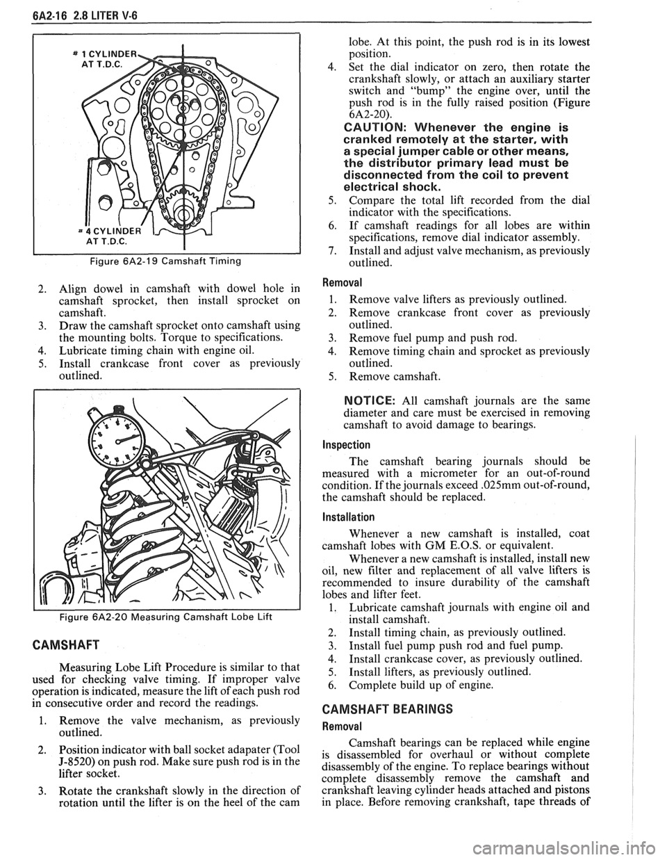
Figure 6A2-19 Camshaft Timing
2. Align dowel in camshaft with dowel hole in
camshaft sprocket, then install sprocket on
camshaft.
3. Draw the camshaft sprocket onto camshaft using
the mounting bolts. Torque to specifications.
4. Lubricate timing chain with engine oil.
5. Install crankcase front cover as previously
outlined.
Figure 6A2-20 Measuring Camshaft Lobe Lift
CAMSHAFT
Measuring Lobe Lift Procedure is similar to that
used for checking valve timing. If improper valve
operation is indicated, measure the lift of each push rod
in consecutive order and record the readings.
1. Remove the valve mechanism, as previously
outlined.
2. Position
indicator with ball socket adapater (Tool
5-8520) on push rod. Make sure push rod is in the
lifter socket.
3. Rotate the crankshaft slowly in the direction of
rotation until the lifter is on the heel of the cam lobe.
At this point, the push rod is in its lowest
position.
4. Set the dial indicator on zero, then rotate the
crankshaft slowly, or attach an auxiliary starter
switch and "bump" the engine over, until the
push rod is in the fully raised position (Figure
6A2-20).
CAUTION: Whenever the engine is
cranked remotely at the starter, with
a special jumper cable or other means,
the distributor primary lead must be
disconnected from the coil to prevent
electrical shock.
5. Compare the total lift recorded from the dial
indicator with the specifications.
6. If camshaft readings for all lobes are within
specifications, remove dial indicator assembly.
7. Install and adjust valve mechanism, as previously
outlined.
Removal
1. Remove valve lifters as previously outlined.
2. Remove crankcase front cover as previously
outlined.
3. Remove fuel pump and push rod.
4. Remove timing chain and sprocket as previously
outlined.
5. Remove camshaft.
NOTICE: All camshaft journals are the same
diameter and care must be exercised in removing
camshaft to avoid damage to bearings.
Inspection
The camshaft bearing journals should be
measured with a micrometer for an out-of-round
condition. If the journals exceed
.025mm out-of-round,
the camshaft should be replaced.
Installation
Whenever a new camshaft is installed, coat
camshaft lobes with
GM E.O.S, or equivalent.
Whenever a new camshaft is installed, install new
oil, new filter and replacement of all valve lifters is
recommended to insure durability of the camshaft
lobes and lifter feet.
1. Lubricate camshaft journals with engine oil and
install camshaft.
2. Install timing chain, as previously outlined.
3. Install fuel pump push rod and fuel pump.
4. Install crankcase cover, as previously outlined.
5. Install
lifters, as previously outlined.
6. Complete build up of engine.
CAMSHAFT BEARINGS
Removal
Camshaft bearings can be replaced while engine
is disassembled for overhaul or without complete
disassembly of the engine. To replace bearings without
complete disassembly remove the camshaft and
crankshaft leaving cylinder heads attached and pistons
in place. Before removing crankshaft, tape threads of
Page 396 of 1825
V-8 ENGINE 6A3.17
4. Set dial indicator on zero, then rotate the
crankshaft slowly, or attach an auxiliary starter
switch and "bump" the engine over, until the
push rod is fully raised position.
e Whenever the engine is cranked remotely at
the started, with a special jumper cable or
other means, the distributor primary lead
should be disconnected from the distributor
(coil).
5. Compare the total lift recorded from the dial
indicator with specifications.
6. If camshaft readings for all lobes are within
specifications, remove dial indicator assembly.
7. Install and adjust valve mechanism as outlined.
Removal
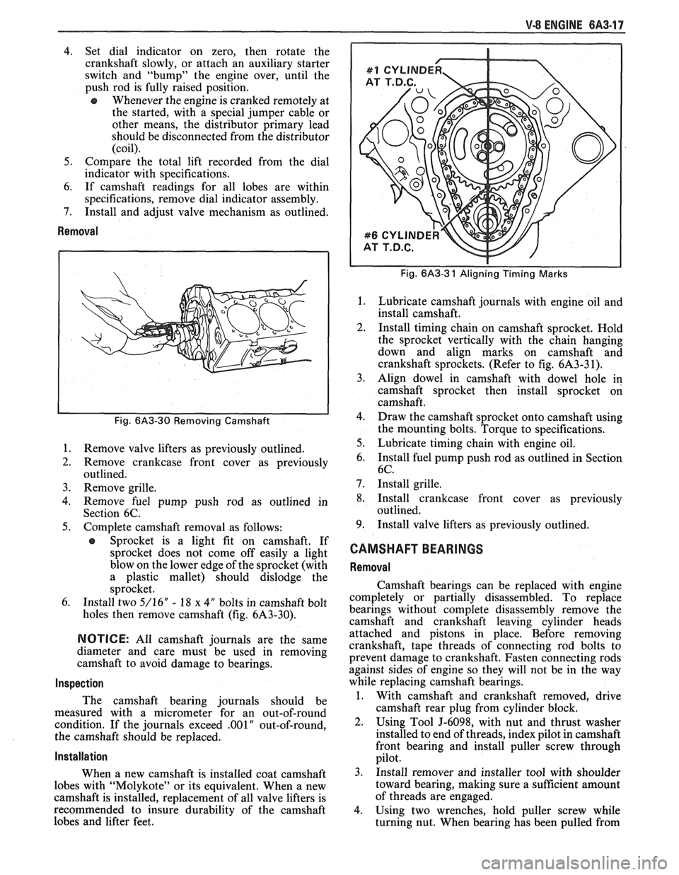
Fig. 6A3-30 Removing Camshaft
1.
Remove valve lifters as previously outlined.
2. Remove crankcase front cover as previously
outlined.
3. Remove grille.
4. Remove fuel pump push rod as outlined in
Section 6C.
5. Complete camshaft removal as follows:
e Sprocket is a light fit on camshaft. If
sprocket does not come off easily a light
blow on the lower edge of the sprocket (with
a plastic mallet) should dislodge the
sprocket.
6. Install two 5/16" - 18 x 4" bolts in camshaft bolt
holes then remove camshaft (fig. 6A3-30).
NOTICE: All camshaft journals are the same
diameter and care must be used in removing
camshaft to avoid damage to bearings.
Inspection
The camshaft bearing journals should be
measured with a micrometer for an out-of-round
condition. If the journals exceed
.001" out-of-round,
the camshaft should be replaced.
Installation
When a new camshaft is installed coat camshaft
lobes with "Molykote" or its equivalent. When a new
camshaft is installed, replacement of all valve lifters is
recommended to insure durability of the camshaft
lobes and lifter feet.
Fig. 6A3-3 1 Aligning Timing Marks
Lubricate camshaft journals with engine oil and
install camshaft.
Install timing chain on camshaft sprocket. Hold
the sprocket vertically with the chain hanging
down and align marks on camshaft and
crankshaft sprockets. (Refer to fig. 6A3-3 1).
Align dowel in camshaft with dowel hole in
camshaft sprocket then install sprocket on
camshaft.
Draw the camshaft sprocket onto camshaft using
the mounting bolts. Torque to specifications.
Lubricate timing chain with engine oil.
Install fuel pump push rod as outlined in Section
6C.
Install grille.
Install crankcase front cover as previously
outlined.
Install valve lifters as previously outlined.
CAMSHAFT BEARINGS
Removal
Camshaft bearings can be replaced with engine
completely or partially disassembled. To replace
bearings without complete disassembly remove the
camshaft and crankshaft leaving cylinder heads
attached and pistons in place. Before removing
crankshaft, tape threads of connecting rod bolts to
prevent damage to crankshaft. Fasten connecting rods
against sides of engine so they will not be in the way
while replacing camshaft bearings.
1. With camshaft and crankshaft removed, drive
camshaft rear plug from cylinder block.
2. Using Tool J-6098, with nut and thrust washer
installed to end of threads, index pilot in camshaft
front bearing and install puller screw through
pilot.
3. Install remover and installer tool with shoulder
toward bearing, making sure a sufficient amount
of threads are engaged.
4. Using two wrenches, hold puller screw while
turning nut. When bearing has been pulled from
Page 591 of 1825
6E2-CZ-16 DRIVEABILITY AND EMISSIONS - 5.OL (WIN E)
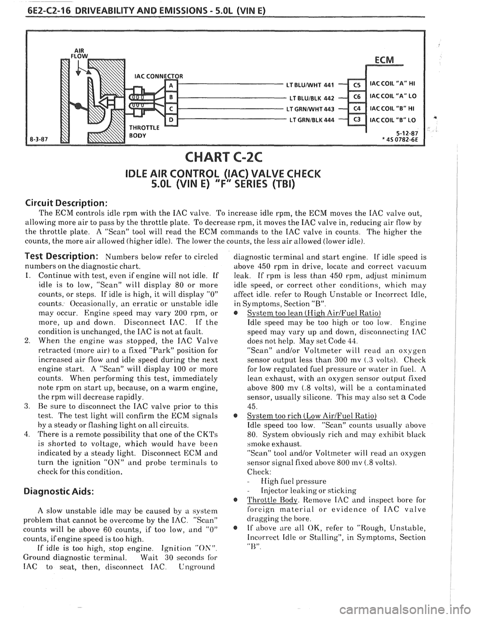
CHART C-2C
IDLE AIR CONTROL (IAC) VALVE CHECK
5.OL (VIN E) "F'" SERIES (TBI)
Circuit Description:
The ECM controls idle rprn with the IAC valve. To increase idle rpm, the ECM moves the IAC valve out,
allowing more air to pass by the throttle plate. To decrease rpm, it moves the IAC valve in, reducing air flow by
the throttle plate. A "Scan" tool will read the
ECM commands to the IAC valve in counts.
The higher the
counts, the more air allowed (higher idle). The lower the counts, the less air allowed (lower idle).
Test Description: Numbers below refer to circled
numbers on the diagnostic chart.
1. Continue with test, even if engine will not idle. If
idle is to low, "Scan" will display 80 or more
counts, or steps. If idle is high, it will display
"0"
counts. Occasionally, an erratic or unstable idle
may occur.
Engine speed may vary 200 rpm, or
more, up and down. Disconnect IAC. If the
condition is unchanged, the IAC is not at fault.
2. When the engine was stopped, the IAC Valve
retracted (more air) to a fixed "Park" position for
increased air flow and idle speed during the next
engine start. A "Scan" will display 100 or more
counts. When performing this test, immediately
note rprn on start up, because, on a warm engine,
the rprn will decrease rapidly.
3. Be sure to disconnect the IAC valve prior to this
test.
The test light will confirm the ECM signals
by
a steady or flashing light on all circuits.
4. There is a remote possibility that one of the
CKTs
is shorted to voltage, which would have been
indicated by a steady light. Disconnect ECM and
turn the ignition
"ON" and probe terminals to
check for this condition.
Diagnostic Aids:
A slow unstable idle may be caused by a system
problem that cannot be overcome by the
IAC. "Scan"
counts will be above 60 counts, if too low,
and "0"
counts, if engine speed is too high.
If idle is too high, stop engine. Ignition "Oh'".
Ground diagnostic terminal. Wait 30 seconds for
IAC to seat, then, disconnect IAC. Lnground
diagnostic terminal and start engine. If idle speed is
above 450 rprn in drive, locate and correct vacuum
leak. If rpm is less than 450 rpm,
ad,jrlst minimum
idle speed, or correct other conditions, which may
affect idle. refer to Rough Unstable or Incorrect Idle,
in Symptoms, Section
"R".
@ System too lean (Hi.gh AirJFuel Ratio)
Idle speed may be too high or too low. Engine
speed may vary up and down, disconnecting IAC
does not help. May set Code
33.
"Scan" and/or Voltmeter will read an oxygen
sensor output less than 300 mv
(.3 volts). Check
for low regulated fuel pressure or water in
fuel. A
lean exhaust, with an oxygen sensor outpirt fixed
above 800
mv (.8 volts), will be a contaminated
sensor, usually silicone. This may also set
a Code
45.
@ System too rich (Low AirIFuel Ratio)
Idle speed too low. "Scan" counts usually above
80. System obviously rich and may exhibit black
srnoke exhaust.
"Scan" tool and/or Voltmeter will
read an oxygen
sensor signal fixed above 800
mv (.8 volts).
Check:
- High fuel pressure
- Injector leaking or sticking
@ Throttle Body. Remove IAC and inspect bore for
foreign material or evidence of
IAC valve
dragging the bore.
@ If above ;
e all OK, refer to "Rough, Unstable,
Incorrect Idle or Stalling", in Symptoms, Section
"I<".
Page 655 of 1825
6E3-A-2 2.88, (VIM S) DRIVEABILITY AND EMISSIONS
'Fa SERIES
COMPUTER HARNESS
C1 Electronic Control Module (ECM)
C2 ALDL diagnostic connector
C3 "SERVICE ENGINE
SOON" light
C4 ECM powerlfuel pump fuse
C5 ECM harness ground
C6 Fuse panel
C8 Fuel pump test connector
(ALDL"G")
C9 MAFfuse
CONTROLLED DEVICES
1 Fuel injector
2
Idle air control motor
3 Fuel pump relay
5 Trans. Conv. Clutch connector
6a Remote ignition coil
8 Engine coolant fan relay
9 Air control solenoid (M.T. only)
12 Exhaust Gas Recirculation solenoid
0 INFORMATION SENSORS
B Exhaust oxygen
C Throttle position D Coolant temperature
F Vehicle speed
K Mass Air Flow
S Power steering pressure switch
T Manifold Air Temperature
U AIC pressure fan switch
13 AIC compressor relay
,..,a :'"' NOT ECM 'ONNECTED 15 Fuel vapor canister solenoid N1 Crankcase vent valve (PCV) 17 bass air flow sensor relay N4 Engine temp. switch (telltale)
N5 Engine temp. sensor (gage) Exhaust Gas Recirculation valve
N6 Oil press. switch (telltale)
N7 Oil press, sensor (gage)
N8 Oil press. swich (fuel pump)
N10 Cold start fuel injection switch
N11 Cold start valve 7-29-87 N12 Deceleration Valve (MIT only)
N13 Fan Override Switch *5S 2127-6E
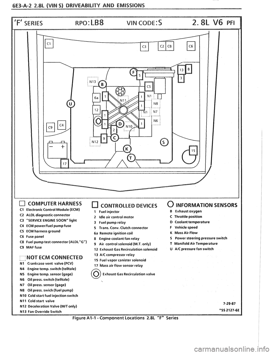
Figure Al-l - Component Locations 2.8L "F" Series
Page 755 of 1825
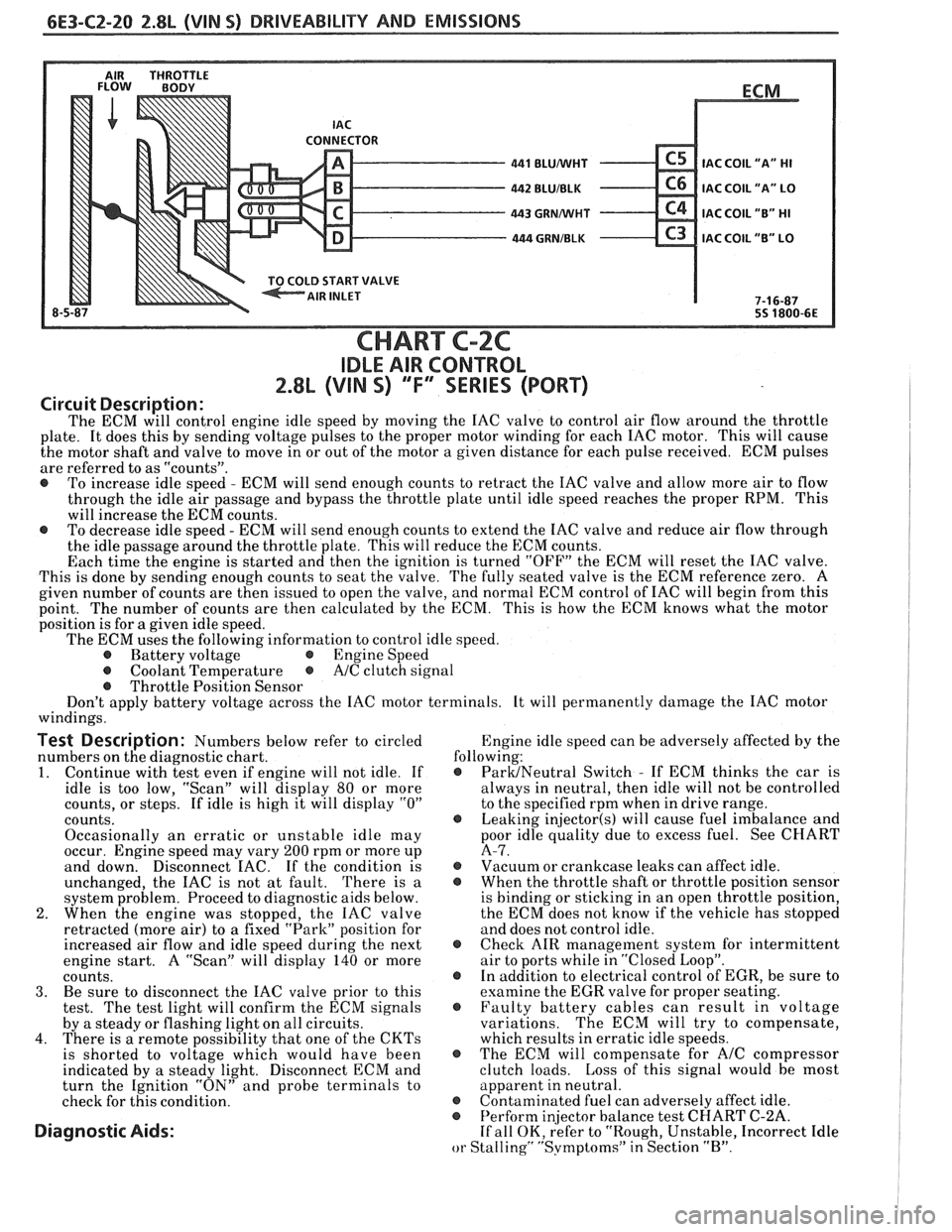
6E3-C2-20 2.8L (VIN S) DRIVEABILITY AND EMISSIONS
AIR THROTTLE FLOW BODY
LD START VALVE
8-5 BLUNVHT
BLUIBLK
GRMNVHT
. GRNIBLK
ECM
.
IAC COIL
"A" HI
IAC COIL "A" LO
IAC COIL "B" HI
C3 IAC COIL "B" LO
7-1 6-87
55 1800-6E
CHART C-2C
IDLE AIR CONTROL
2.8L (VIN S) ""F-SERIES (PORT)
Circuit Description:
The ECM will control engine idle speed by moving the IAC valve to control air flow around the throttle
plate. It does this by sending voltage pulses to the proper motor winding for each IAC motor. This will cause
the motor shaft and valve to move in or out of the motor a given distance for each pulse received. ECM pulses
are referred to as "counts".
@ To increase idle speed - ECM will send enough counts to retract the IAC valve and allow more air to flow
through the idle air passage and bypass the throttle plate until idle speed reaches the proper RPM. This
will increase the ECM counts.
@ To decrease idle speed - ECM will send enough counts to extend the IAC valve and reduce air flow through
the idle passage around the throttle plate. This will reduce the ECM counts.
Each time the engine is started and then the ignition is turned "OFF" the ECM will reset the IAC valve.
This is done by sending enough counts to seat the valve. The fully seated valve is the ECM reference zero. A
given number of counts are then issued to open the valve, and normal ECM control of IAC will begin from this
point. The
number of counts are then calculated by the ECM. This is how the ECM knows what the motor
position is for
a given idle speed.
The ECM uses the following information to control idle speed.
@ Battery voltage @ Engine Speed
@ Coolant Temperature @ A/C clutch signal
@ Throttle Position Sensor
Don't apply battery voltage across the IAC motor terminals. It will permanently damage the IAC motor
windings.
Test Description: Numbers below refer to circled Engine
idle speed can be adversely affected by the
numbers on the diagnostic chart. following:
1. Continue
with test even if engine will not idle. If @ ParUNeutral Switch - If ECM thinks the car is
idle is too low, "Scan" will display
80 or more always
in neutral, then idle will not be controlled
counts, or steps. If idle is high it will display
"0" to the specified rpm when in drive range.
counts.
@ Leaking injector(s) will cause fuel imbalance and
Occasionally an erratic or unstable idle may poor
idle quality due to excess fuel. See CHART
occur. Engine speed may vary
200 rpm or more up A-7.
and down. Disconnect
EAC. If the condition is @ Vacuum or crankcase leaks can affect idle.
unchanged, the IAC is not at fault. There is
a @ When the throttle shaft or throttle position sensor
system problem. Proceed to diagnostic aids below. is
binding or sticking in an open throttle position,
2. When the engine was stopped, the IAC valve the
ECM does not know if the vehicle has stopped
retracted (more air) to a fixed "Park" position for and does not control idle.
increased air flow and idle speed during the next
@ Check AIR management system for intermittent
engine start. A "Scan" will display
140 or more air
to ports while in "Closed Loop".
counts. @ In addition to electrical control of EGR, be sure to
3. Be sure to disconnect the IAC valve prior to this examine the
EGR valve for proper seating.
test. The test light will confirm the ECM signals @ Faulty battery cables can result in voltage
by a steady or flashing light on all circuits. variations. The
ECM will try to compensate,
4. There is a remote possibility that one of the CKTs which results in erratic idle speeds.
is shorted to voltage which would have been @ The ECM will compensate for A/C compressor
indicated by a steady light. Disconnect ECM and clutch
loads. Loss of this signal would be most
turn the Ignition "ON" and probe terminals to apparent
in neutral.
check for this condition.
@ Contaminated fuel can adversely affect idle. @ Perform in
or Stalling" "Svmptoms" in Section "B".
Page 907 of 1825
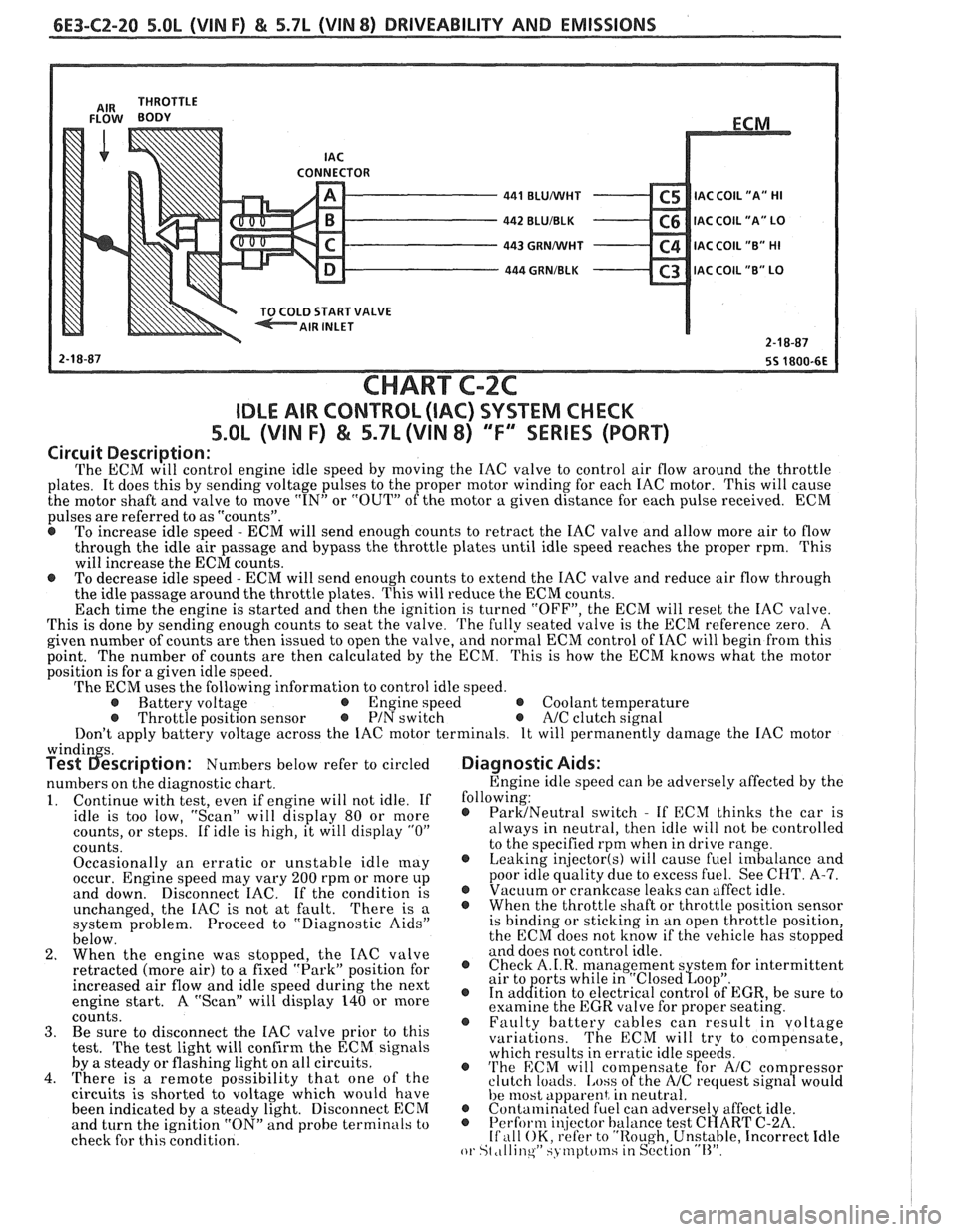
6E3-C2-20 5.0L (VIN F) & 5.7L (WIN 8) DRIVEABILITY AND EMISSIONS
CONNECTOR - 441 BLUMlHT C5 IAC C0lL1'A" HI - 442 BLUIBLK C6 IAC COIL "A" LO - 443 GRNMlHT C4 IAC COIL "B" HI - 444 GRNIBLK C3 lAC COIL "B" LO v
START VALVE
CHART C-2C
IDLE AIR CONTROL (IAC) SYSTEM CHECK
S.OL (VIN F) & 5.7L (VIN 8) "F'" SERIES (PORT)
Circuit Description:
The ECM will control engine idle speed by moving the IAC valve to control air flow around the throttle
plates. It does this by sending voltage pulses to the proper motor winding for each IAC motor. This will cause
the motor shaft and valve to move
"IN" or "OUT" of the motor a given distance for each pulse received. ECM
pulses are referred to as "counts".
@ To increase idle speed - ECM will send enough counts to retract the IAC valve and allow more air to flow
through the idle air passage and bypass the throttle plates until idle speed reaches the proper rpm. This
will increase the ECM counts.
e To decrease idle speed - ECM will send enough counts to extend the IAC valve and reduce air flow through
the idle passage around the throttle plates. This will reduce the ECM counts.
Each time the engine is started and then the ignition is turned "OFF", the ECM will reset the IAC valve.
This is done by sending enough counts to seat the valve.
The fully seated valve is the ECM reference zero. A
given number of counts are then issued to open the valve, and normal ECM control of IAC will begin from this
point. The
number of counts are then calculated by the ECM. This is how the ECM knows what the motor
position is for a given idle speed.
The ECM uses the following information to control idle speed.
@ Battery voltage @ Engine speed @ Coolant temperature @ Throttle position sensor @ PIN switch e A/C clutch signal
Don't apply battery voltage across the IAC motor terminals. It will permanently damage the IAC motor
windin s. Test 6escription: Numbers below refer to circled
numbers on the diagnostic chart.
1. Continue with test, even if engine will not idle. If
idle is too low, "Scan" will display 80 or more
counts, or steps. If idle is high, it will display
"0"
counts.
Occasionally an erratic or unstable idle
[nay occur. Engine speed may vary 200 rpm or more up
and down. Disconnect IAC. If the condition is
unchanged, the IAC is not at fault.
There is a
system problem. Proceed to "Diagnostic Aids"
below.
2. When the engine was stopped, the IAC valve
retracted (more air) to
a fixed "Park" position for
increased air flow and idle speed during the next
engine start. A "Scan" will display 140 or more
coiints. 3. Be sure to disconnect the IAC valve prior to this
test.
The test light will confirm the ECM signals
by a steady or flashing light on all circuits.
4. There is a remote possibility that one of the
circuits is shorted to voltage which would have
been indicated by a steady light. Disconnect ECM
and turn the ignition "ON" and probe terminals to
check for this condition.
Diagnostic Aids:
Engine idle speed can be adversely affected by the
following:
@ ParMNeutral switch - If ECM thinks the car is
always in neutral, then idle will not be controlled
to the specified rpm when in drive range.
@ Leaking injector(s) will cause fuel imbalance and
poor idle quality due to excess fuel. See CHT.
A-7. @ Vacuum or crankcase leaks can affect idle. @ Whenthethrottleshaftorthrottlepositionsensor
is binding or sticking in an open throttle position,
the ECM does not know if the vehicle has stopped
and does not control idle.
@ Check A.I.R. management s stem for intermittent
air to orts while in "~losed~oo~". @ In ad&tion to electrical control of EGR, be sure to
examine the EGR valve for proper seating.
@ Faulty battery cables can result in voltage
variations. The ECM will try to compensate,
which results in erratic idle speeds.
@ 'I'he ECM will com ensate for A/C com ressor
clutch loacls. [.ass ofthe NC request sign8 would
he 11lost apparent, in neutral. @ Contalninatecl fuel can adverse1 affect idle. @ Perform i~!jector balance test C~ART C-2A. If ,111 OK, refer to "Rough, Unstable, Incorrect Idle or St ,tllinqW SJ tnptcfinsiin S~'ction "11''.
Page 1211 of 1825
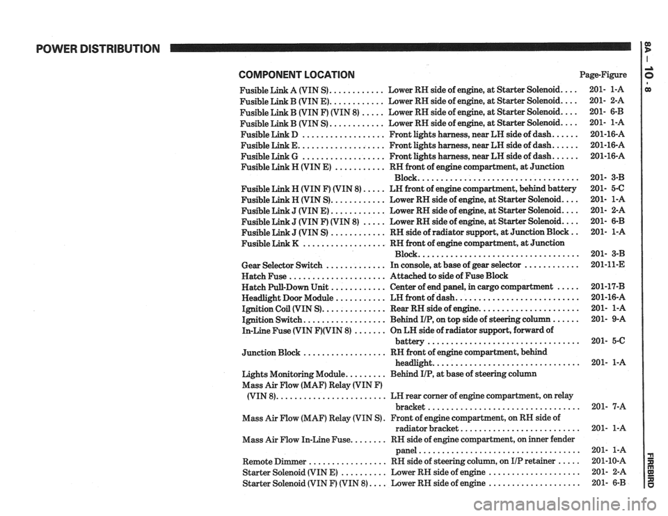
POWER DISTRIBUTION
COMPONENT LOCATlON Page-Figure
Fusible Link A (VIN S)
............ Lower RH side of engine. at Starter Solenoid ....
Fusible Link B (VIN E) ............ Lower RH side of engine. at Starter Solenoid ....
Fusible Link B (VIN F) (VIN 8) ..... Lower RH side of engine. at Starter Solenoid ....
............ Fusible Link B (VIN S) Lower
RH side of engine. at Starter Solenoid ....
Fusible Link D .................. Front lights harness. near LH side of dash ......
Fusible Link E ................... Front lights harness. near LH side of dash ......
Fusible Link G .................. Front lights harness. near LH side of dash ......
Fusible Link H (VIN E) ........... RH front of engine compartment. at Junction
Block
...................................
Fusible Link N (VIN F) (VIN 8) ..... LN front of engine compartment. behind battery
Fusible Link H (VIN S)
............ Lower RH side of engine. at Starter Solenoid ....
J (VIN E) ............ Lower RH side of engine, at Starter Solenoid ....
J (VIN F) (VIN 8) ..... Lower RH side of engine, at Starter Solenoid ....
J (VIN S) ............ RH side of radiator support. at Junction Block ..
.................. Fusible Link K RN front of engine compartment. at Junction
Block
...................................
Gear Selector Switch ............. In console, at base of gear selector ............
Hatch Fuse ..................... Attached to side of Fuse Block
Hatch Pull-Down Unit
............ Center of end panel, in cargo compartment .....
Headlight Door Module ........... LH front of dash ...........................
Ignition Coil (VIN S) .............. Rear RH side of engine ......................
Ignition Switch .................. Behind IIP. on top side of steering column ......
In-Line Fuse (VIN F)(VIN 8) ....... On LH side of radiator support. forward of
................................. battery
.................. Junction Block RH front of engine compartment. behind
................................ headlight
Lights Monitoring Module
......... Behind IIP. at base of steering column
Mass Air Flow (MAF) Relay (VIN
F)
........................ (VIN 8) LH rear corner of engine compartment, on relay
................................. bracket
Mass Air Flow (MAF) Relay (VIN S)
. Front of engine compartment. on RH side of
radiator bracket
..........................
Mass Air Flow In-Line Fuse ........ RN side of engine compartment, on inner fender
panel
...................................
Remote Dimmer ................. RH side of steering column. on IIP retainer .....
Starter Solenoid (VIN E) .......... Lower RH side of engine ....................
Starter Solenoid (VIN F) (VIN 8) .... Lower RH side of engine ....................
Page 1454 of 1825
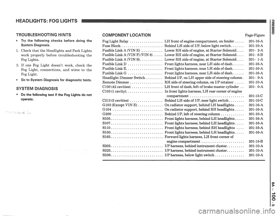
HEADLIGHTS: FOG LIGHTS
TROUBLESHOOTING HINTS
r Try the following checks before doing the
System Diagnosis
.
1 . Check that the Headlights and Park Lights
work properly before troubleshooting the
Fog Lights
.
2 . If one Fog Light doesn't work, check the
Fog Light. connections. and wires to the
Fog Light
.
Go to System Diagnosis for diagnostic tests .
SYSTEM DIAGNOSIS
Do the following test if the
operate
.
-., U .
Fog Lights do not
COMPONENT LOCATION Page-Figure
Fog Light Relay
................. LH front of engine compartment. on fender .....
Fuse Block ...................... Behind LH side of IIP. below light switch .......
Fusible Link A (VIN E) ........... Lower RN side of engine. at Starter Solenoid ....
Fusible Link A (VIN F) (VIN 8) ..... Lower RH side of engine. at Starter Solenoid ....
Fusible Link A (VIN S) ............ Lower RH side of engine. at Starter Solenoid ....
Fusible Link D .................. Front lights harness. near kH side of dash ......
Fusible Link E ................... Front lights harness. near LH side of dash ......
Fusible Link 6 .................. Front lights harness. near LN side of dash ......
......... . er Switch Behind IIP. on EN upper side
of steering column
Remote
Dimmer ................. RH side of steering column. on IIP retainer ..... .
C100 (42 cavities) ................ LH front of dash. left of brake master cylinder ..
C103 (1 cavity) ................... In front lights harness. LH rear corner of engine
compartment
............................
C213 (3 cavities) ................. Behind LH side of IIP. near Light switch ........
6103 (Except VIN E) ............. On radiator support. behind LR headlights .....
6104 .......................... On radiator support. behind RN headlights .....
6200 .......................... Behind IIP. left of steering column ............
S105 ........................... Front lights harness. behind LH headlights .....
S107 ........................... Front lights harness. behind LH headlights .....
S110 ........................... Front lights harness. behind RH headlights ....
S150 ........................... Front lights harness. behind LH headlights .....
S165 ........................... Forward lights harness. LH front corner of
engine compartment
......................
S205 ........................... I/P harness. behind instrument cluster .........
S225 ........................... I/P harness. behind instrument cluster .........
S236 ........................... IIP harness. below light switch ...............