1988 PONTIAC FIERO tailgate
[x] Cancel search: tailgatePage 22 of 1825

MAINTENANCE AND LUBRICATION OB-5
Throttle linkage inspection -- Inspect for inter-
ference, binding, damaged or missing parts.
Engine drive belts inspection - Inspect all
belts for cracks, fraying and wear. Adjust or replace as
needed.
Rear axle service (if equipped) - Check gear
lubricant level and add if needed. For cars equipped with a
limited slip rear axle, fluid does not require changing
(except Caprice and Corvette
- change fluid and required
additive at first
7,500 miles (12 500 km). See your
Owner's Manual or "Recommended Fluids
& Lubricants
Chart" in this section.
IF YOU USE YOUR GAR TO PULL A TRAILER,
CHANGE GEAR LUBRICANT EVERY 7,500 MILES
(12 500 KM).
NOTICE: A large loss in this system may indicate a
problem. Have it inspected and repaired at once.
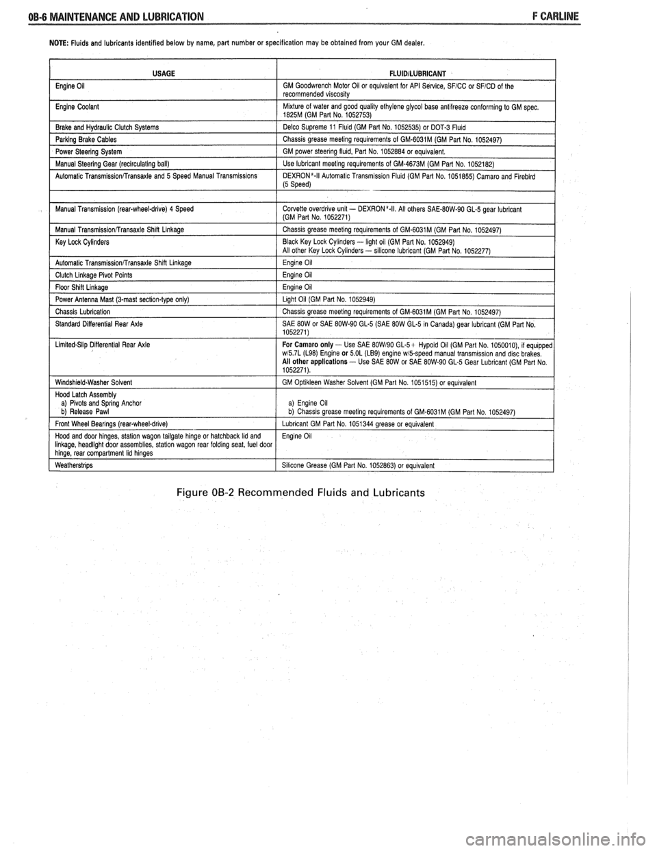
Power antenna - Clean and then lubricate power
antenna mast. The proper lubricant as shown in Figure
OB-2 should be used.
AT LEAST ONCE A YEAR
Lap and shoulder belts condition and opera-
tion
- Inspect belt system, including webbing, buckles,
latch plates, retractors, guide loops and anchors.
Moveable head restraint operation - On cars
with moveable restraints, make sure restraints stay in the
desired position. (See adjustment instructions in your
Owner's Manual.)
Seatback latch and recliner operation on
cars equipped
with recliner seat --- Be sure seat-
backs latch on those cars with folding seats using mechan-
ical latches. Make sure the recliner is holding by pushing
and pulling on the top of the
seatback while it is reclined.
See your Owner's Manual for seat operating information.
Spare tire and jack storage- Be alert to rattles
in rear of car. Make sure the space tire, all jacking equip-
ment, any tire inflator and any covers or doors are securely
stowed at all times. Oil jack ratchet or screw mechanism
after each use.
Key lock service - Lubricate key lock cylinder at
least annually.
Body lubrication service - Lubricate all body
door hinges including the tailgate or hatchback lid (if
equipped). Also lubricate the body hood, fuel door and
rear compartment hinges and latches including interior
glove box and counsel doors, and any folding seat
hardware.
"Fansmissionltransaxle neutral or clutch
starl switch operation
CAUnON: Before pedorming the follow-
ing safety switch check, be sure to have
enough room around the car. Then, firmly
apply both the parking brake (see your
Owner's Manual for procedure) and the
regular brakes. Do not use the accelerator pedal.
If the engine
starls, be ready to turn
off the ignition promptly. Take these pre-
cautions because the car could move
without warning and possibly cause per-
sonal injury or properly damage. On auto-
matic transmissionltransaxle cars, try to
starl the engine in each gear. The starler
should crank only in "Park" or "Neutral."
On manual transmissionltransaxle cars,
place the
shiR lever in "Neutral," push the
clutch halfway and try to starl. The starler
should crank only when the clutch is fully
depressed.
Steering column lock operation
- While
parked, try to turn key to "Lock" in each gear range. The
key should turn to "Lock" only when gear is in "Park" on
automatic or "Reverse" on manual
transmissionltransax-
le. On cars with key release lever, try to turn key toULock"
without depressing the lever. The key should turn to
"Lock" only with the key lever depressed. On all vehicles,
the key should come out only in "Lock."
Parking brake and transmissionltransaxle
"Park" mechanism operation
CAUT1ON:Before checking the holding
ability of the parking brake and automatic
transmissionltransaxle "Park" mecha-
nism, park on a fairly steep hill with
enough room for movement in the down-
hill direction. To reduce the risk of person-
al injury or property damage, be prepared
to apply the regular brakes promptly if the
car begins to move.
To check the parking brake, with the engine running and
transmission/transaxle in "Neutral." slowly remove foot
pressure from the regular brake pedal (until the car is held
by only the parking brake).
To check the automatic transmissionltransaxle "Park"
mechanism holding ability, release all brakes after shift-
ing the transmissionltransaxle to "Park."
ljnderbody flushing - At least every spring,
tlush from the underbody with plain water any corrosive
materials used for ice and snow removal and dust control.
Take care to thoroughly clean any areas where mud and
other debris can collect.
Sediment packed in closed areas
of the vehicle should be loosened before being flushed.
Engine cooling system service - Inspect
coolant and freeze protection. If dirty or rusty, drain, flush
and refill with new coolant. Keep coolant
at the proper
mixture as specified in your Owner's Manual. This pro-
vides proper freeze protection. corrosion inhibitor level
and engine operating temperature. Inspect hoses and re-
place if cracked. swollen or deteriorated. Tighten hose
clamps. Clean outside of radiator and air conditioning
condensor. Wash radiator filler cap and neck.
To help
ensure proper operation. a pressure test of both the cooling
system and cap is also recommended. (See maintenance
schedule charts in Figure
OB-l for the recommended
coolant change interval.)
Page 23 of 1825

NOTE: Fluids and lubricants identified below by name, part number or specification may be obtained from your GM dealer.
Figure 00-2 Recommended Fluids and Lubricants
USAGE
Engine
Oil
Engine Coolant
Brake and
Hydraul~c Clutch Systems
Parking Brake Cables
Power Steering System
Manual
Steerlng Gear (reclrculat~ng ball)
Automatic
Transrn~ssionRransaxle and 5 Speed Manual Transm~ss~ons
Manual Transm~ssion (rear-wheel-drive) 4 Speed
Manual
Transm~ss~onRransaxle Shin Linkage
Key Lock Cylinders
Automatic Transmlss~onfrransaxle Shlft Llnkage
Clutch Llnkage Plvot Po~nts
Floor Sh~n L~nkage
Power Antenna Mast (3-mast sect~on-type only)
Chass~s Lubr~cation
Standard D~fferent~al Rear Axle
L~m~ted-Sl~p D~flerent~al Rear Axle
W~ndsh~eld.Washer Solvent
Hood Latch Assembly
a)
Plvots and Sprlng Anchor
b) Release Pawl
Front Wheel Bearings
(rearqwheel-drive)
Hood and door hlnges, statlon wagon tailgate hlnge or hatchback Ild and Ilnkage, headl~ght door assembl~es, statlon wagon rear foldrng seat, fuel door hlnge, rear compartment Ihd hlnges
Weatherstr~ps
FLUlDlLUBRlCANT
GM Goodwrench Motor 011 or equivalent for API Se~lce, SFICC or SFICD of the
recommended v~scos~ty
M~xture of water and good qual~ty ethylene glycol base antllreeze conforming to GM spec 1825M (GM Part No 1052753)
Delco Supreme 11
Fluld (GM Part No 1052535) or DOT-3 Fluld
Chass~s grease meetlng requirements of GM-6031M (GM Part No 1052497)
GM power
steerlng flu~d, Part No 1052884 or equivalent
Use lubricant meetlng requirements of GM-4673M (GM Part No 1052182)
DEXR0N'-II Automat~c Transm~ss~on Flu~d (GM Part No 1051855) Camaro and Flreblrd (5 Speed)
Corvette overdr~ve unlt - DEXRON a.II All others SAE-80W-90 GL-5 gear lubr~cant (GM Part No 1052271)
Chass~s grease meetlng requirements of GM-6031M (GM Part No 1052497)
Black Key Lock
Cyl~nders - light oil (GM Par1 No. 1052949)
All other Key Lock Cyl~nders - sllicone lubrlcant (GM Part No 1052277)
Eng~ne 011
Eng~ne 011
Eng~ne 011
Llght 011 (GM Part No 1052949)
Chass~s grease meetlng requirements of GM-6031M (GM Part No 1052497)
SAE
80W or SAE 80W-90 GL-5 (SAE 80W GL-5 In Canada) gear lubricant (GM Part No
1052271)
For Camaro only
- Use SAE BOW190 GL-5+ Hypold 011 (GM Part No 1050010), 11 equ~pped wl5 7L (L98) Englne or 5 OL (LB9) engine wmpeed manual transm~ss~on and disc brakes
All other applications - Use SAE 80W or SAE 80W-90 GL-5 Gear Lubr~cant (GM Part No
1052271)
GM
Opt~kleen Washer Solvent (GM Part No 1051515) or equ~valent
a) Eng~ne 011 b) Chass~s grease meet~ng requirements of GM.6031M (GM Part No 1052497)
Lubricant GM Part No 1051344 grease or equivalent
Eng~ne 011
S~l~cone Grease (GM Part No 1052863) or equivalent
Page 1798 of 1825

SEATS - F STYLE 9H-15
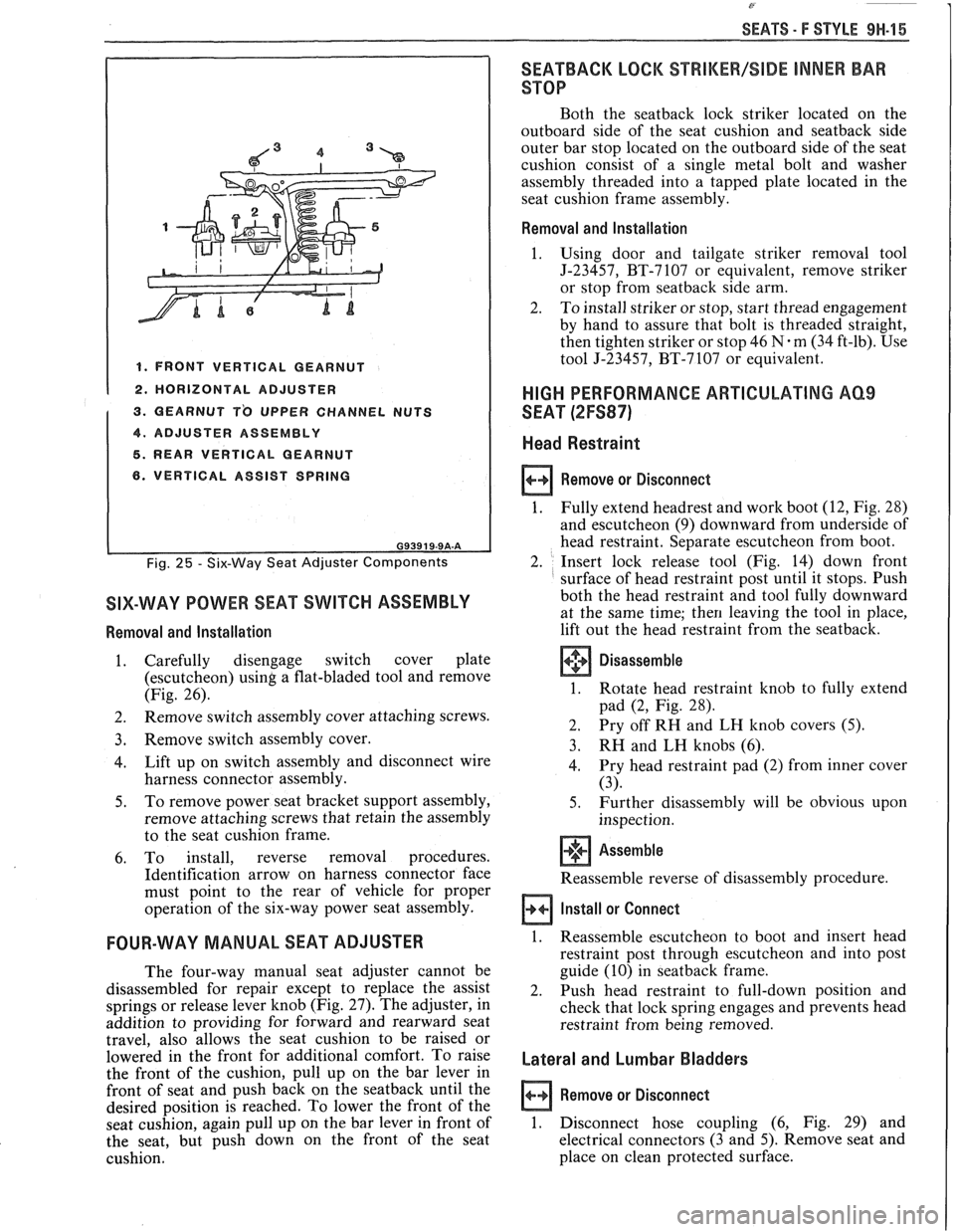
I 1. FRONT VERTICAL GEARNUT I 1 2. HORIZONTAL ADJUSTER
1 3. QEARNUT T'O UPPER CHANNEL NUTS
1 4. ADJUSTER ASSEMBLY I 5. REAR VERTICAL GEARNUT
6. VERTICAL ASSIST SPRING
Fig. 25 - Six-Way Seat Adjuster Components
SIX-WAY POWER SEAT SWITCH ASSEMBLY
Removal and Installation
1. Carefully disengage switch cover plate
(escutcheon)
using a flat-bladed tool and remove
(Fig. 26).
2. Remove
switch assembly cover attaching screws.
3. Remove switch assembly cover.
4. Lift
up on switch assembly and disconnect wire
harness connector assembly.
5. To
remove power seat bracket support assembly,
remove attaching screws that retain the assembly
to the seat cushion frame.
6. To install, reverse removal procedures.
Identification arrow on harness connector face
must point to the rear of vehicle for proper
operation of the six-way power seat assembly.
FOUR-WAY MANUAL SEAT ADJUSTER
The four-way manual seat adjuster cannot be
disassembled for repair except to replace the assist
springs or release lever knob (Fig.
27). The adjuster, in
addition to providing for forward and rearward seat
travel, also allows the seat cushion to be raised or
lowered in the front for additional comfort. To raise
the front of the cushion, pull up on the bar lever in
front of seat and push back on the
seatback until the
desired position is reached. To lower the front of the
seat cushion, again pull up on the bar lever in front of
the seat, but push down on the front of the seat
cushion.
SEATBACK LOCK %%RIMEW/SIDE INNER BAR
STOP
Both the seatback lock striker located on the
outboard side of the seat cushion and
seatback side
outer bar stop located on the outboard side of the seat
cushion consist of a single metal bolt and washer
assembly threaded into a tapped plate located in the
seat cushion frame assembly.
Removal and Installation
1.
Using door and tailgate striker removal tool
J-23457, BT-7107 or equivalent, remove striker
or stop from
seatback side arm.
2. To install striker or stop, start thread engagement
by hand to assure that bolt is threaded straight,
then tighten striker or stop 46
N.m (34 ft-lb). Use
tool J-23457, BT-7107 or equivalent.
HIGH PERFORMANCE ARTICULATING AQ9
SEAT (2FS87)
Head Restraint
Remove or Disconnect
1.
Fully extend headrest and work boot (12, Fig. 28)
and escutcheon
(9) downward from underside of
head restraint. Separate escutcheon from boot.
2. Insert lock release tool (Fig. 14) down front
surface of head restraint post until it stops. Push
both the head restraint and tool fully downward
at the same time;
then leaving the tool in place,
lift out the head restraint from the seatback.
Disassemble
1. Rotate head restraint knob to fully extend
pad
(2, Fig. 28).
2. Pry
off RH and LH knob covers
(5).
3. RH and LH knobs (6).
4. Pry
head restraint pad (2) from inner cover
(3).
5. Further disassembly will be obvious upon
inspection.
+'+ Assemble [I]
Reassemble reverse of disassembly procedure.
Install or Connect
1. Reassemble escutcheon to boot and insert head
restraint post through escutcheon and into post
guide (10) in
seatback frame.
2. Push head restraint to full-down position and
check that lock spring engages and prevents head
restraint from being removed.
Lateral and Lumbar Bladders
Remove or Disconnect
1. Disconnect hose coupling (6, Fig. 29) and
electrical connectors (3 and 5). Remove seat and
place on clean protected surface.