1988 PONTIAC FIERO refrigerant type
[x] Cancel search: refrigerant typePage 44 of 1825
AIR CONDITIONING 1B-1
SECTION 1B
R COND
When performing air conditioning diagnosis on vehicles equipped with a catalytic converter, it will be necessary to
WARM the engine to a NORMAL operating temperature BEFORE attempting to idle the engine for periods greater
than five
(5) minutes. Once the engine attains normal idle, diagnosis and adjustments can be made.
CONTENTS
.................. General Description .................................. 1B-1 Accumulator Assembly Service .1B-19
.......................... C.C.O.T. A!C System ................................ 1B-1 On-Vehicle Sewice ..... 1B-20
....................................... System Components - Functional ................. 1B-2 Blower Motor .1B-20
..................................... System Components - Control ..................... 1B-3 Hi-Blower Relay 1B-20
...................................... Relays and Switches ................................... 1B-3 Blower Resistor 1B-20
Diagnosis ................................................. 1B-5 Controller, Blower Switch or Vacuum
................................................ Testing the Refrigerant System ...................... 1B-5 Valve .lB-20
Insufficient Cooling "Quick-Check Temperature Control Cable ....................... .1B-20
.................................... Procedure.. ............................................. 1B-5 Vacuum
Harness .lB-20
C.C.O.T. A/C System Diagnostic Control Wiring Harness ........................... .1B-20
..... ................................. Procedure.. ............................................. 1B-8 Heater
Core .. .lB-21
................................ Leak Testing ........................................... 1B-12 Lower Heater Outlet 1B-21
............................... Service Procedures ................................. .1B-12 Heater Module Case .lB-21
.......................... O-Ring Replacement ................................ .1B- 12 Pressure Cycling Switch .1B-21
....................................... Handling Refrigerant- 12 ............................ .1B- 13 Vacuum Tank .lB-21
Discharging, Adding Oil, Evacuating Liquid Line .......................................... .1B-23
and
Charging Procedures - AIC Accumulator ......................................... .1B-23
.................................... Systems .............................................. .1B-14 Evaporator Core .1B-24
In-Line Air Conditioning Evaporator Case .................................... .1B-24
.......................................... Filter
Installation.. .................................. .1B- 18 Compressor .lB-24
.............................................
................ Expansion Tube (Orifice) Service .1 B- 19 Condenser IB-24
GENERAL DESCRIPTION
All engines are equipped with a fixed displace- evaporator temperature. The pressure cycling switch
ment (R-4) air conditioning compressor. This
com- is the freeze protection device in the system and
pressor may cycle on and off under normal air
senses refrigerant pressure on the suction side of the
conditioning demand. system. This switch is located on a standard
Schrader- -
All air conditioning systems that use the fixed
displacement R-4 compressor are referred to as
C. C.O.T. (Cycling Clutch, Orifice Tube) type sys-
tems. This is the same system that has been used on
all General Motors vehicles in the past several years.
The C.C.O.T. NG System
The Cycling Clutch Orifice Tube (C.C.O.T.)
refrigeration system is designed to cycle a compressor
on and off to maintain desired cooling and to prevent
evaporator freeze. Passenger compartment comfort is
maintained by the temperature lever on the controller.
Control of the refrigeration cycle (on and off
operation of the compressor) is done with a switch
which senses low-side pressure as an indicator of type
valve low-side fitting. During air temperatures
over 10°C
(50°F), the equalized pressures within the
charged
A/C system will close the contacts of the
pressure switch. When an air conditioning mode
(max, norm, bi-level, defrost) is selected, electrical
energy is supplied to the compressor clutch coil. AS
the compressor reduces the evaporator pressure
to
approximately 175 kPa (25 psi), the pressure switch
will open, de-energizing the compressor clutch.
As
the system equalizes and the pressure reaches approxl-
mately 315 kPa (46 psi), the pressure switch contacts
close, re-energizing the clutch coil. This cycling
coy
tinues and maintains average evaporator discharge air
temperature at approximately 1°C (33°F). Because of
this cycling, some slight increases and decreases of
engine speedlpower may be noticed under certain con-
ditions. This is normal as the system is designed
to
cycle to maintain desired cooling, thus preventing
evaporator freeze-up.
Page 46 of 1825
AIR CONDITIONING 1 B-3
A low-side pressure Schrader valve service fit-
ting is located near the top of the accumulator. A
similar Schrader fitting may be provided for mounting
the pressure cycling switch. It is not necessary to dis-
charge the system to replace the switch. The accumu-
lator is serviced only as a replacement assembly.
Heater Core
The heater core heats the air before it enters the
car. Engine coolant is circulated through the core to
heat the outside air passing over the fins of the core.
The core is functional at all times (no water valve) and
may be used to temper conditioned air in
A/C mode,
as well as heat or vent mode.
SYSTEM COMPONENTS --- CON"FOL
Controller
The operation of the A/C system is controlled by
the switches and the lever on the control head. The
compressor clutch and blower are connected electri-
cally to the control head by a wiring harness. The
blower circuit is open in the off mode and air flow is
provided by the four blower speeds available in the
remaining modes. Cooled and dehumidified air is
available in the max, normal, bi-level and defrost
modes.
Temperature is controlled by the position of the
temperature lever on the control head. A cable con-
nects this lever to the temperature door which controls
air flow through the heater core. As the temperature
lever is moved through its range of travel, a sliding
clip on the cable at the temperature valve connection
should assume a position assuring that the temperature
door will seat in both extreme positions. Temperature
door position is independent of mode selection. The
temperature cable attaches to the right side of the air
conditioning module. The temperature door on some
models is controlled electrically, thereby eliminating
the need for the temperature cable.
The electric engine cooling fan on some cars is
not part of the
A/C system; however, the fan is
operational any time the
A/C control is in Max.,
Norm, or Bi-Level modes. Some models provide for
engine cooling fan operation when the controller is in
the defrost mode. This added feature is part of the
A/C
controller function and is aimed at preventing exces-
sive compressor head temperatures. It also allows the
A/C system to function more efficiently. On some
models during road speed (above
35 mph) conditions
when air flow through the condenser coil is adequate
for efficient cooling, the engine cooling fan will be
turned off. The operation of the cooling fan is con-
trolled by the ECM through the cooling fan relay.
Complete wiring diagrams and diagnosis for the
AIC Electrical System are in Section 8A. Section 8A
also contains additional diagnostic information
regarding air flows and vacuum logic.
Vacuum Lines
Vacuum lines are molded to a connector which
is attached to a vacuum control switch on the control
head assembly.
In case of leakage or hose collapse, it will not be
necessary to replace the entire harness assembly.
Replacement can be made by cutting the hose and
inserting a plastic connector. If an entire hose must be
replaced, cut all hoses off at the connector and then
attach hoses directly to the control head vacuum
switch. (NOTE: The Fiero uses an electric motor to
control mode selection. Therefore, it will not have a
vacuum harness.
)
Vacuum Tank
During heavy acceleration, the vacuum supply
from the carburetor drops. A check valve in the vac-
uum tank maintains vacuum so that, under load condi-
tions, vacuum will be available for continuous use.
REWVS AND SWITCHES
High-Pressure Compresssr Gut-OFF Switch
The high-side, high-pressure cut-off switch in
the rear head of the compressor is a protective device
intended to prevent excessive compressor head pres-
sures and reduce the chance of refrigerant escape
through a safety relief valve. Normally closed, this
switch will open the circuit at a high-side pressure of
approximately 2700
kPa (430 psi 9 20 psi) and
reclose the circuit at approximately 1379 kPa (200 psi
9 50 psi).
Lsw-Pressure Cut-On Switch
Compressor protection is provided on some cars
by a low-pressure cut-off switch which will open in
the event of a low-charge condition. This switch can
be located in the liquid line or in the rear head of the
compressor. This switch will also keep the compres-
sor from running during cold weather.
Pressure eyesing Switch
The refrigeration cycle (on and off operation of
the compressor) is controlled by a switch which
senses the low-side pressure as an indicator of evapo-
rator temperature. The pressure cycling switch is the
freeze protection device in the system and senses
refrigerant pressure on the suction side of the system.
This switch is located on a standard Schrader-type
valve low-side fitting. This switch also provides com-
pressor cut-off during cold weather.
Additional compressor protection results from
the operating characteristics of the low-side pressure
cycling system. If a massive discharge occurs or the
orifice tube becomes plugged, low-side pressures
could be insufficient to close the contacts of the pres-
sure switch. In the event of a low charge, insufficient
cooling accompanied by rapid compressor clutch
cycling will be noticed at high air temperatures.
Page 47 of 1825

18-4 AIR CONDITIONING
If replacement of the pressure cycling switch is
necessary, it is important to note that this may be done
without removing the refrigerant charge.
A Schrader-
type valve is located in the pressure switch fitting.
During replacement of the pressure switch, a new
oiled O-ring must be installed and the switch assem-
bled to the specified torque of
6- 13 N*m (5- 10 lb. ft.).
Power Steering Gut-OH, or Anticipate
Switch
Engine idle quality on some cars is maintained
by cutting off the compressor (switch normally
closed) when high power steering loads are imposed.
On other cars the switch (normally open) provides a
signal to the ECM to allow engine control systems to
compensate for high-power steering loads.
Wide-Open Tkroale (WOT) Compressor
Cut-Out
Switch
A switch located on the throttle corltrols of some
carburetor equipped cars opens the circuit to the com-
pressor clutch during full throttle acceleration. The
switch activates a relay that controls the compressor
clutch. During full throttle acceleration
on cars
equipped with TBI or
Em, the TPS sends a signal to
the ECM, thereby controlling the compressor clutch.
Air Conditioning Time Delay Relay
This relay on some cars controls the current to
the entire air conditioning system and provides a short
delay of air conditioning operation upon start-up.
Constant Run Relay
Engine idle quality on some cars is maintained
by a "constant run" system (constant run relay) that
eliminates compressor cycling during engine idle for a
predetermined time after the vehicle has come to rest
from road speed.
If the idle period continues for an
extended time, the
A/C system may return to a con-
ventional C.C.O.T. mode for a short time to prevent
system freeze-up. The
A/C control relay and constant
run relays are both controlled by the Electronic Con-
trol Module (ECM) which determines operating con-
ditions by evaluating input from the distributor
(engine speed), vehicle speed sensor, air sensor and
A/C compressor "on" signal.
5-PRESSURE CYCLING 8-EXPANSION TUBE
SWITCH (ORIFICE)
6-DESSICANT BAG O-LIQUID LINE
7-OIL BLEED HOLE
10-PRESSURE RELIEF
VALVE
@ ee LOW PRESSURE LIQUID HIGH PRESSURE LIQUID LOW PRESURE VAPOR HIGH PRESSURE VAPOR
Figure 2 A/C System - Typical
Page 56 of 1825
-
AIR CONDlTlQNlNG 1B-'13
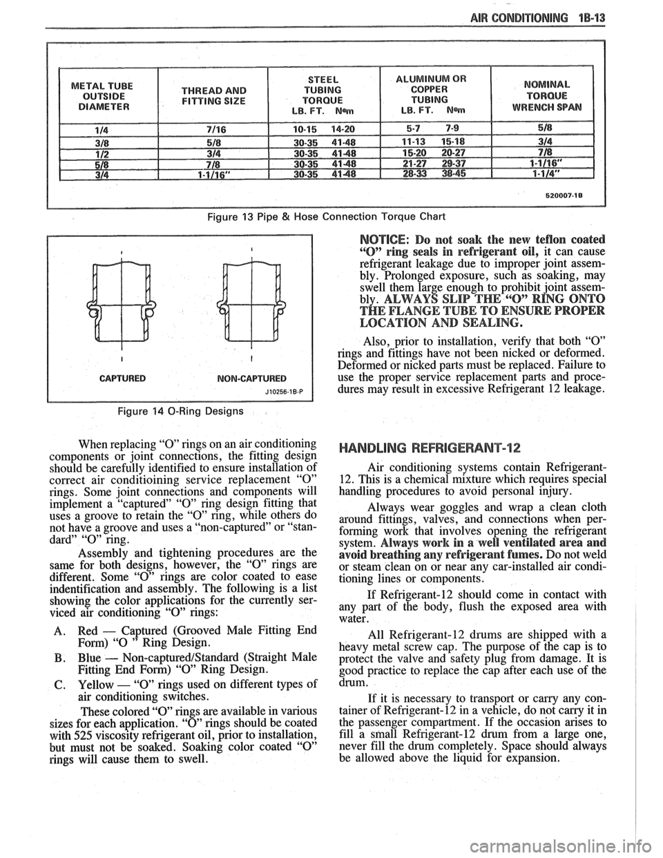
METAL TUBE
THREAD AND
FITTING SIZE
Figure 13 Pipe 8( Hose
CAPTURED NOM-CAPTURED
Figure 14 0-Ring Designs
When replacing "0" rings on an air conditioning
components or joint connections, the fitting design
should be carefully identified to ensure installation of
correct air conditioining service replacement
"0"
rings. Some joint connections and components will
implement a "captured"
"0" ring design fitting that
uses a groove to retain the
"0" ring, while others do
not have a groove and uses a "non-captured" or "stan-
dard"
"0" ring.
Assembly and tightening procedures are the
same for both designs, however, the
"0" rings are
different. Some
"0" rings are color coated to ease
indentification and assembly. The following is a list
showing the color applications for the currently ser-
viced air conditioning
"0" rings:
A. Red
- Captured
(Grooved Male Fitting End
Fom) "0 " Ring Design.
B . Blue - Non-captured/Standard (Straight Male
Fitting End
Form) "09' Ring Design.
61. Yellow - "0" rings used on different types of
air conditioning switches.
These colored "O" rings are available in various
sizes for each application.
"0" rings should be coated
with
525 viscosity refrigerant oil, prior to installation,
but must not be soaked. Soaking color coated
"0"
rings will cause them to swell.
Connection Torque Chart
NOTICE: Do not soak the new teflon coated
"0" ring seals in refrigerant oil, it can cause
refrigerant leakage due to improper joint assem-
bly. Prolonged exposure, such as soaking, may
swell them large enough to prohibit joint assem-
bly.
ALWAYS SLIP THE 6"O" RING ONTO
THE FLANGE TUBE TO ENSURE PROPER
LOCATION AND SEALING.
Also, prior to installation, verify that both "09'
rings and fittings have not been nicked or deformed.
Deformed or nicked
parts must be replaced. Failure to
use the proper service replacement parts and proce- dures may result in excessive Refrigerant
12 leakage.
HANDLING REFRIGERANT12
Air conditioning systems contain Refrigerant-
12. This is a chemical mixture which requires special
handling procedures to avoid personal injury.
Always wear goggles and wrap a clean cloth
around fittings, valves, and connections when per-
forming work that involves opening the refrigerant
system.
Always work in a well ventilated area and
avoid breathing
any refrigerant fumes. Do not weld
or steam clean on or near any car-installed air condi-
tioning lines or components.
If Refrigerant-12 should come in contact with
any part of the body, flush the exposed area with
water.
All
Refrigerant-12 drums are shipped with a
heavy metal screw cap. The purpose of the cap is to
protect the valve and safety plug from damage. It is
good practice to replace the cap after each use of the
drum.
If it is necessary to transport or carny any con-
tainer of Refrigerant-12 in a vehicle, do not
carry it in
the passenger compartment. If the occasion arises to
fill a
sfnall Refrigerant-12 drum from a large one,
never fill the drum completely. Space should always
be allowed above the liquid for expansion.
Page 61 of 1825
LlOQllD LiNE FILTER INSTALLATION
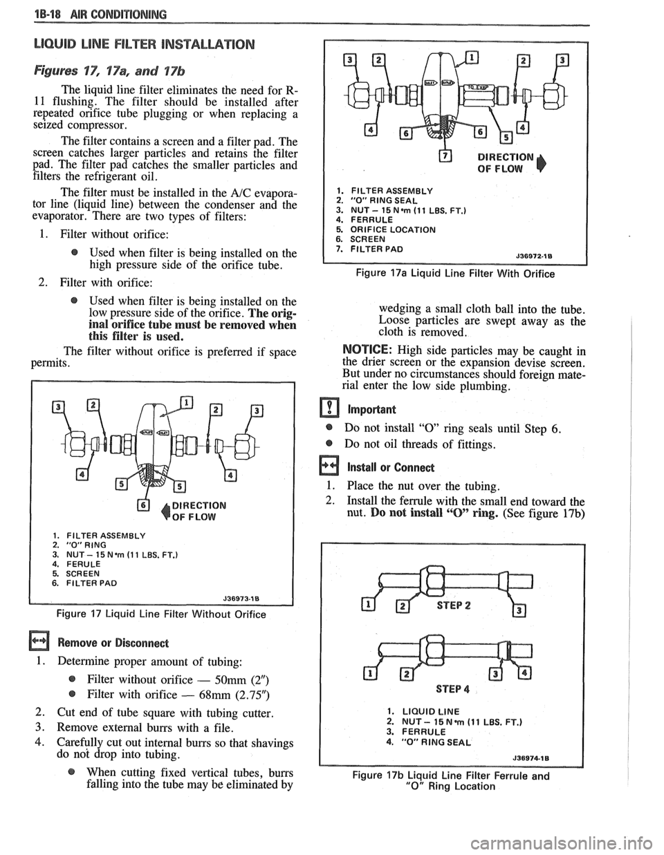
Figures 'IT", 17% and 17b
The liquid line filter eliminates the need for R-
11 flushing. The filter should be installed after
repeated orifice tube plugging or when replacing a
seized compressor.
The filter contains a screen and a filter pad. The
screen catches larger particles and retains the filter
pad. The filter pad catches the smaller particles and filters the refrigerant oil.
The filter must be installed in the
A/C evapora-
tor line (liquid line) between the condenser and the
evaporator. There are two types of filters:
@ DIRECTION
OF FLOW
1. FILTER ASSEMBLY 2. "0" RlNG SEAL 3. NUT- 15N.m (11 LBS. FT.) 4. FERRULE
1. Filter without orifice: 5. ORIFICE LOCATION
@ Used when filter is being installed on the 7. FILTER PAD
high pressure side of the orifice tube. Figure 17a Liquid Line Filter With Orifice
2. Filter with orifice:
@ Used when filter is being installed on the
low pressure side of the orifice.
The orig-
inal orifice tube must be removed when
this filter is used.
The filter without orifice is preferred if space
permits.
DIRECTION
OF FLOW
1. FILTER ASSEMBLY 2. "0"RING 3. NUT - 15 Nem (1 1 LBS. FT.) 4. FERULE
5. SCREEN
6. FILTER PAD
Figure 17 Liquid Line Filter Without Orifice
Remove or Disconnect
1. Determine proper amount of tubing:
@ Filter without orifice - 50mm (2")
@ Filter with orifice - 68mm (2.95")
2. Cut end of tube square with tubing cutter
3. Remove external burrs with a file.
4. Carefully cut out internal burrs so that shavings
do not drop into tubing. wedging a small cloth ball
into the tube.
Loose particles are swept away as the
cloth is removed.
NOTICE: High side particles may be caught in
the drier screen or the expansion devise screen.
But under no circumstances should foreign mate-
rial enter the low side plumbing.
m Important
@ Do not install "0 ring seals until Step 6.
@ Do not oil threads of fittings.
a Install or Connect
1. Place the nut over the tubing. -
2. Install the ferrule with the small end toward the
nut.
Do not install ""0' ring. (See figure 17b)
STEP 4
1. LIQUID LINE 2. NUT - 15 N m (1 1 LBS. FT.) 3. FERRULE 4. "0" RlNG SEAL
@ When cutting fixed vertical tubes, burrs Figure 17b Liquid Line Filter Ferrule and falling into the tube may be eliminated by "0" Ring Location
Page 63 of 1825
18-28 AIR CONDITIONING
DO NOT REPLACE the accumulator assembly
when:
1. Merely a dent is found in the outer shell of the
accumulator.
2. A
vehicle is involved in a collision and no phys-
ical perforation to the accumulator is found.
OM-VEHICLE SERVICE
R-"1 CHARGING CAPACITIES
The 420ml (14 fl. oz.) disposable can of R-12
refrigerant is equivalent to .399 kg (. 88 lb.).
BLOWER MOTOR
a Remove or Disconnect
1. Disconnect negative battery cable.
2. Remove motor cooling tube.
3. Disconnect electrical connections.
4. Remove blower motor attaching screws, remove
motor and case assembly.
5. Loosen retaining nut and remove blower cage
from motor shaft.
6. Inspect blower cage for broken vanes, etc.
Replace if necessary.
Install or Connect
1. Reverse removal procedure to reinstall. Replace
seals or sealant as required.
HI-BLOWER RELAY
Relay is a plug-in type with connector mounted
on top of the evaporator case.
BLOWER RESISTOR
Remove or Disconnect
1. Disconnect negative battery cable.
2. Disconnect electrical connections.
3. Remove two (2) screws, remove resistor.
Install or Connect
1. Reverse removal procedure to reinstall.
CONTROLLER, BLOWER SWITCH OR
WCUUM VALVE
Remove or Disconnect
1. Disconnect negative battery cable.
2. Remove NC control-radio console trim plate.
3. Remove three (3) NC control retaining screws.
4. Pull A/C control out and disconnect electrical
and vacuum connections and remove tempera-
ture cable.
5. Remove A/C control and replace vacuum valve
or blower switch as required.
Install or Connect
1. Reverse removal procedure to reinstall. Install
lower right screw in controller first to align con-
troller in console.
TEMPERATURE CONTROL CABLE,
VACUUM HARNESS
Remove or Disconnect
1. Remove the following hush panel(s):
a. Vacuum Harness - R.H. and L.H. hush
panel.
b. Temperature Cable
- R.H. hush panels.
Remove
controller/radio console trim plate.
Remove three (3) controller screws and pull
controller partially out of console.
Disconnect controller
end(s) of temperature
cable
andlor vacuum harness.
Disconnect component
end(s) of temperature
cable
andlor vacuum harness.
Install or Conned
1. Reverse removal procedure to reinstall. When
installing controller, install lower right screw
first to align controller location. Replace any
retaining straps, etc. removed.
2. Perform functional check of controller.
CONTROL WlRlNG HARNESS
a Remove or Disconnect
1. Disconnect negative battery cable.
2. Remove
control/radio console trim plate and
hush panels (see Section
8C).
3. Remove three (3) screws holding control in con-
sole and pull control out far enough to discon-
nect electrical and vacuum connector. Remove
controller.
4. Remove instrument panel carrier (see Section
8C).
5. Remove heater case covers (core and mode door
sides).
6. Remove two (2) interior screws and one (1)
exterior nut holding case to cowl. Pull left side
of case back to gain access to harness at cowl.
Case will still be retained by one (I) screw
behind the evaporator core
- do not attempt
complete removal of case. -
7. Loosen cowl grommet and disconnect purple
vacuum line.
Page 78 of 1825
AIR CONDITIONING 1B-35
I
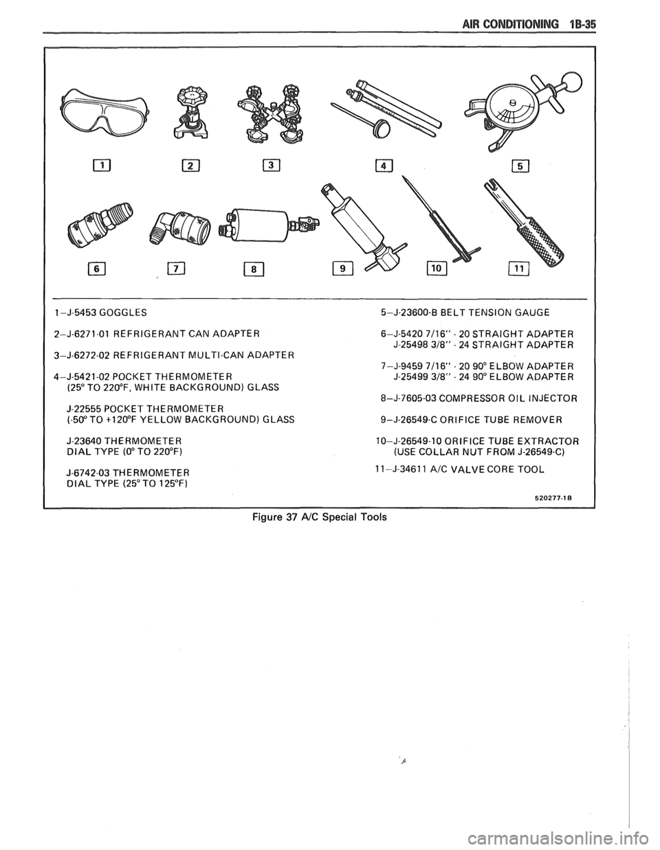
1 -J-5453 GOGGLES 5-J-23600-B BELT TENSION GAUGE
2-J-6271-01 REFRIGERANT CAN ADAPTER
3-J-6272-02 REFRIGERANT MULTI-CAN ADAPTER
4-J-5421-02 POCKET THERMOMETER
(25" TO 220°F, WHITE BACKGROUND) GLASS
J-22555 POCKET THERMOMETER
(-50" TO +I 20°F YELLOW BACKGROUND) GLASS
J-23640 THERMOMETER
DlAL TYPE (0" TO 220°F)
I
J-6742-03 THERMOMETER DlAL TYPE (25" TO 125°F) 6-J-5420
7/16" - 20
STRAIGHT ADAPTER
J-25498
318" - 24 STRAIGHT ADAPTER
7-J-9459 7/16"
- 20 90" ELBOW ADAPTER
J-25499 318" - 24 90" ELBOW ADAPTER
8-J-7605-03 COMPRESSOR OIL INJECTOR
9-J-26549-C ORIFICE TUBE REMOVER
10-J-26549-10 ORIFICE TUBE EXTRACTOR
(USE COLLAR NUT FROM J-26549-C)
11 -J-34611
A/C VALVE CORE TOOL
Figure 37 AIC Special Tools
Page 98 of 1825
R-4 818 CONDITIONING COMPRESSOR OVERHAUL 1D1-19
retainers are to be removed, remove two sets and
then rotate compressor and Holding Fixture
J-25008-A in vise for access to the remaining two
valve plates and retainers.
Install or Connect
1. Install Discharge Valve Plates and/or Retainers.
Reposition compressor and Holding Fixture in
vise as necessary for access.
Valve plates must
be tight
following retainer assembly.
2. Reinstall compressor Shell as described in
SHELL AND O-RINGS replacement
procedures.
3. Evacuate and charge the refrigerant system
according to the directions in Section
1B.
CYLINDER AND SHAFT ASSSEMBLY
Remove or Disconnect
Discharge the refrigerant system according to the
directions in Section
1B.
Remove the Clutch Plate and Hub assembly as
described in CLUTCH PLATE AND HUB
removal procedure.
Perform Steps
1 through 4 of CLUTCH ROTOR
AND BEARING removal procedure but do not
loosen or remove the pulley rim mounting screws.
Remove the Clutch Rotor and Bearing, Clutch
Coil and Pulley Rim as an assembly. Be careful
not to drop the Puller Guide J-25031, when
removing the assembly.
Remove the shaft seal as described in SHAFT
SEAL removal procedure.
Remove the front head as described in FRONT
HEAD REMOVAL procedure.
Remove the thrust and belleville washers as
described in THRUST AND BELLEVILLE
WASHERS removal procedures.
Remove the compressor shell as described in
SHELL removal procedure.
Remove the discharge valve plate and retainer as
described in DISCHARGE VALVE PLATE
AND RETAINER removal procedure.
Remove the high pressure relief valve as
described in
HIGH PRESSURE RELIEF
VALVE REMOVAL PROCEDURE.
L
Install or Connect
1. Replace above parts in opposite order.
2. Evacuate and charge the refrigerant system
according to the directions in Section
1B.
LEAK TESVING (EXTERNAL AND INTERNAL)
Bench-Check Procedure
1. Install Test Plate J-9625-A on Rear Head of
compressor.
2. Attach center hose of Manifold Gage Set on
Charging Station to a refrigerant drum standing
in an upright position and open valve on drum.
3. Connect Charging Station high and low pressure
lines to corresponding fittings on Test Plate J-9625-A, using
5-5420 Gage
Adapters if hoses
are not equipped with valve depressors.
Suction port (low-side) of compressor has
large internal opening. Discharge port
(hi-side) has smaller internal opening into
compressor.
Open low-pressure control, high-pressure control
and refrigerant control on Charging Station to
allow refrigerant vapor to flow into compressor.
Using a Leak Detector, check for leaks at
Pressure Relief Valve, compressor shell to
cylinder, compressor front head seal, and
compressor Shaft Seal. After checking, shut off
low pressure control and high pressure control on
Charging Station.
If an external leak is present, perform the
necessary corrective measures and recheck for
leaks to make certain the leak has been corrected.
Loosen the Manifold Gage hose connections to
the Gage Adapters J-5420 connected to the low
and high sides and allow the vapor pressure to
release from the compressor.
Disconnect both Gage Adapters
5-5420 from the
Test Plate J-9625-A.
Rotate the complete compressor assembly (not
the crankshaft or drive plate hub) slowly several
turns to distribute oil to all cylinder and piston
areas.
Install a shaft nut on the compressor crankshaft
if the drive plate and clutch assembly are not
installed.
Using a box-end wrench or socket and handle,
rotate the compressor crankshaft or clutch drive
plate on the crankshaft several turns to ensure
piston assembly to cylinder wall lubrication.
Connect the Charging Station high pressure line
or a high pressure gage and Gage Adapter J-5420
to the Test Plate J-9625-A high side connector.
Attach an Adapter
9-5420 to the suction or low
pressure port of the Test Plate
J-9625-19 to open
the Schrader-type valve.
Oil will drain out of the compressor suction port
adapter if the compressor is positioned with the
suction port downward.
Attach the compressor to the Holding Fixture
J-25008-A using metric mounting screws. Clamp
the compressor Holding Fixture in a vise so that
the compressor can be manually turned with a
wrench.
Using a wrench, rotate the compressor crankshaft
or drive plate hub ten complete revolutions at a
speed of approximately one-revolution per
second.
Turning the compressor at less than
one-revolution per second can result in a lower
pump-up pressure and disqualify a good pumping
compressor.
Observe the reading on HIGH pressure gage at
the completion of the tenth revolution of the
compressor. The pressure reading for a good
pumping compressor should be 344.75
kPa (50 p.
s.i.) or above. A pressure reading of less than 3 10.
275 kPa (45 p.s.i.) would indicate one or more