1988 PONTIAC FIERO brake rotor
[x] Cancel search: brake rotorPage 21 of 1825
OB-4 MAINTENANCE AND LUBRICATION
Tire and wheel operation - Be alert to a vibra-
tion of the steering wheel or seat at normal highway
speeds. This may mean a wheel balance is needed. Also, a
pull right or left on a straight, level road may show the
need for
a tire pressure adjustment or wheel alignment.
Steering system operation - Be alert to
changes in steering action. An inspection is needed when
the steering wheel is harder to turn or has too much free
play or if unusual sounds are noted when turning or
parking.
Headlight aim operation - Take note of light
pattern occasionally. If beam aim doesn't look right,
headlights should be adjusted.
AT EACH FUEL FILL
Engine oil level check - Check engine oil level
and add if necessary. See your Owner's
Manual for further
details.
NOTICE: A large loss in this system may indicate a
problem. Have it inspected and repaired at once.
Engine coolant level and condition - Check
engine coolant level in coolant reservoir tank and add if
necessary. Replace if dirty or rusty. See your Owner's
Manual for further details.
NOTICE: A large loss in this system may indicate a
problem. Have it inspected and repaired at once.
Windshield washer fluid level check -- Check
washer fluid level in container and add if necessary.
Hood latch operation - When opening hood on
cars equipped with hoods that open from the front, note
the operation of secondary latch. It should keep hood from
opening all the way when primary latch is released. Make
sure that hood closes firmly.
AT LEAST MONTI-ILY
Tire and wheel inspection and pressure
check--
Check tires for abnormal wear or damage. Also,
check for damaged wheels. Keep pressures as shown on
Tire Placard on the driver's door (include spare unless it is
a stowaway). Pressure should b\: checked when tires are
"cold". See "Tires" in Owner's Manual for further
infomation.
Light operation check - Check operation of
license plate light, side-marker lights, headlights includ-
ing high beams, parking lights, taillights, brake lights.
turn signals, backup lights, instrument panel and interior
lights and hazard warning flashers.
Fluid leak check - After the car has been parked
for a while, inspect the surface beneath the car for water,
oil, fuel or other fluids. Water dripping from the air
conditioning system after use is normal. If you notice fuel
leaks or fumes, the cause should be found and corrected at
once.
AT LEAST TWICE A YEAR (FOR EXAMPLE,
EVERY SPRING AND FALL)
Power steering pump fluid level check --
Check power steering pump fluid level in accordance with
Owner's Manual instructions and keep at proper level.
NOTICE: A large loss in this system may indicate a
problem. Have it inspected and repaired at once.
Brake master cylinder reservoir fluid level
check ---- Check fluid and keep at proper level. Note: It is
normal for the brake fluid level to go down slightly as the
brake pads wear
- so be sure to keep reservoir filled.
NOTICE: A large loss in this system may indicate a
problem. Have
it inspected and repaired at once.
Clutch system service --- manual transmis-
sionltransaxle --- For cars equipped with hydraulic
clutch system, check the reservoir fluid level and add fluid
as required. All others, check clutch pedal free travel and
adjust as necessary. See your Owner's Manual for further
details.
~
NOTICE: A large loss in this system may indicate a
problem. Have it inspected and repaired at once.
Weatherstrip Lubrication - Clean surface and
then apply a thin film of silicone grease with a clean cloth.
EACH TIME OIL IS CHANGED
Automatic and manual transmissionltrans-
axle fluid level check - Check transmission/transaxle
fluid level and add as required. (Corvette only) if equipped
with manual transmission
- check fluid in the overdrive
unit and add as required.
NOTICE: A large loss in this system may indicate a
problem. Have
it inspected and repaired at once.
Brake systems inspection - For convenience,
the following should be done when wheels are removed
for rotation: Inspect lines and hoses for proper hookup,
binding, leaks, cracks, chafing, etc. Inspect disc brake
pads for wear and rotors for surface condition. Also in-
spect drum brake linings for wear and cracks. Inspect
other brake parts, including drums, wheel cylinders, park-
ing brake, etc. at the same time. Check parking brake
adjustment.
INSPECT BRAKES MORE OFTEN IF DRIVING
HABITS OR CONDITIONS RESULT IN FREQUENT
BRAKING.
Steering, suspension and front drive axle
boot and seal inspection
- Inspect front and rear
suspension and steering system for damaged, loose or
missing parts, signs of wear or lack of lubrication. Inspect
power steering lines and hoses for proper hookup, bind-
ing, leaks, cracks, chafing, etc. (On cars equipped with
manual steering gear, check for seal leakage.) On
front-
wheel-drive cars, clean then inspect drive axle boot seals
for damage, tears or leakage. Replace seals if necessary.
Exhaust system inspection - Inspect complete
system. Inspect body near the exhaust system. Look for
broken, damaged, missing or out-of-position parts as well
as open seams, holes, loose connections or other condi-
tions which could cause a heat buildup in the tloor pan or
could let exhaust fumes seep into the trunk or passenger
compartment.
Page 143 of 1825
3-18 STEERING, SUSPENSION, TIRES AND WHEELS DIAGNOSIS
VIBRATION COMPLANT TIRE-WHEEL-HUB-AXLE RELATED
Vibrations that are tire or wheel induced can be caused
by two factors: imbalance or
runout. Low-speed vibrations, those less than 40 mph, are
usually runout related. Highway speed vibrations, those
above 40 mph, can be caused by either imbalance or runout. Prior to performing any work, always road test the car
and perform a careful visual inspection for:
- Obvious tire and wheel runout. - Obvious drive 'axle or propeller shaft runout. - Proper inflation pressure. - Wrong trim height. - Bent wheels. - Debris build-up on the tire or wheel. - Loose or missing wheel weights or wheel nuts. - Irregular or excessive tire wear. - Proper tire bead seating on rim. - Damaged tires, such as tread distortions,
separations, or bulges from impact damage. Slight sidewall indentations are normal and will not affect
ride quality.
Balance is the easiest procedure to perform and should,
therefore, be done fist if the vibration occurs at highway
speeds.
An off-car two-plane dynamic balance should first
be performed. This will correct any imbalance in the tire and
wheel assembly.
An oncar fiish balance may also be required. This will correct any brake drum, rotor, or wheel cover imbalance.
Follow the balancing procedures outlined in Section 3E. If balance does not correct the highway speed vibration,
or if the vibration is at low speeds, runout is the probable
cause. Runout can be caused by the tire, wheel, or the way
the wheel attaches to the car. The following procedure
should be used
: A. If runout is suspected, the free runout of the tire
and wheel assembly should first be measured on the car. A
dial indicator with a roller wheel is preferable, but a dial
indicator with button end may be used. Lateral
runout (side
to side) should be measured on the tire's sidewall as close to
the tread shoulder as possible. Radial
runout (up and down)
should be measured on the center tread rib. Some tread
designs may require tightly wrapping a piece of tape around
the center tread circumference for better dial indicator
contact. For measuring wheel
runout follow the "Measuring
Wheel Runout" procedure in Section 3E. Whether measuring
radial or lateral runout, disregard any instantaneous indicator
needle jumps due to sidewall depressions, tread blocks, etc.
Record the total indicator reading, and the location of the
high point of
runout. The,,total tire and wheel oncar runout should be less than ,060 , if either measurement exceeds ,060"~ proceed to Step B.
B. If
the oncy radial or lateral runout measured in
Step A exceeds .060 , mount the tire and wheel assembly on
a dynamic balance machine and again measure the amount of runout. Locate on the machine by the wheel's inside center
pilot hole. Using the same procedure as in Step A, record the
amount of tire and wheel
runout and its high point Location.
Next, measure wheel runout, see Section 3E. If the wheel
exceeds specifications replace the ~heel.,~If the tire and wheel
radial or lateral runout exceeds .050 at the tire tread,
proceed to Step C.
C. If the off-car tire and wheel radial or lateral runout measured in Step 18 exceeds .050", match mount the high radial runout point of tire to low radial runout point of
wheel. Weinflate, mount on the dynamic balance machine,
and again measure and record the radial and lateral runout and its location, as done in Step B. In many cases, match
mounting the tire on the wheel will bring the assembly's
runout into the acceptable range of less than .050". D. If the runout of the tire and wheel assembly is
within limits when measured off the car, yet exceeds the
limits when measured on the car, the attachment of the tire
and wheel assembly to the hub is the probable cause. Rotate
the assembly two wheel studs and recheck the
runout. Several positions may have to be tried to find the best
location.
E. If the assembly runout cannot be reduced to an
acceptable level, remove the tire and wheel assembly and
measure wheel stud
runout with a dial indicator. Zero
the dial indicator button on one stud. Lift button gently
off stud and rotate flange to position next stud against
dial indicator button. Record the
runout on all studs. Dial indicator should read zero when repositioned on first stud
that was checked. If runout exceeds .030", the hub or axle
shaft should be replaced.
Whenever a tire is rotated on the wheel, or a tire or
wheel is replaced, the assembly must be rebalanced.
In addition to balance and tire and wheel free
runout, tire stiffness variation (loaded radial runout) can also cause
a vibration. However, this is impossible to measure without
a TPD (Tire Problem Detector) or a loaded radial
runout buffer.
The TPD is a roller drum that slowly rotates the tire
while under load and mounted on the car. Tire stiffness
variation causes wheel spindle movement which can be
measured.
The loaded radial
runout buffer is a more automated
machine that slowly rotates the tire and wheel off the car
under load with a roller drum and measures the tire's
stiffness variation. It will then "match" the tire to the wheel
by buffing off small amounts of rubber from the outer tread
rows at the stiff spot. This procedure is usually effective,
especially when used
as a measuring device and for fine
buffing only.
The
TPD and loaded radial runout buffer are two
methods that will measure or correct tire stiffness variation,
tire
runout, and wheel runout at the same time. However,
because such equipment is not always available, and both
have their disadvantages, the more basic procedure of
measuring free
runout with a dial indicator, as previously
detailed, is usually more practical. The free runout of the
tire will usually correspond with the tire's stiff spot.
The substitution method of vibration diagnosis can also
be used. Install
a known good set of tire and wheel
assemblies. If these correct the vibration, the original
assemblies should be reinstalled one at
a time until the
vibration returns. This will point out the tire with excess
stiffness variation.
Tire stiffness variation will be higher or lower depending
on the direction of tire rotation.
Fig. 20 Vibration Complaint Chart (2 of 2)
Page 216 of 1825
FRONT SUSPENSION 3C-5
CALIPER
Remowd
NOTICE: See "Notice" on Page 3C-1 of this section.
1. Remove two thirds of the total fluid capecity from the meter cylinder reservoir that supplies fluid to the rystemrls) baing ~~iCed. Removal of the fluid is ne-
cessary to prevent nservoir overflow when the caliper
piston is pushed back in its bore to remove the caliper. Dircard the.brake fluid removed.
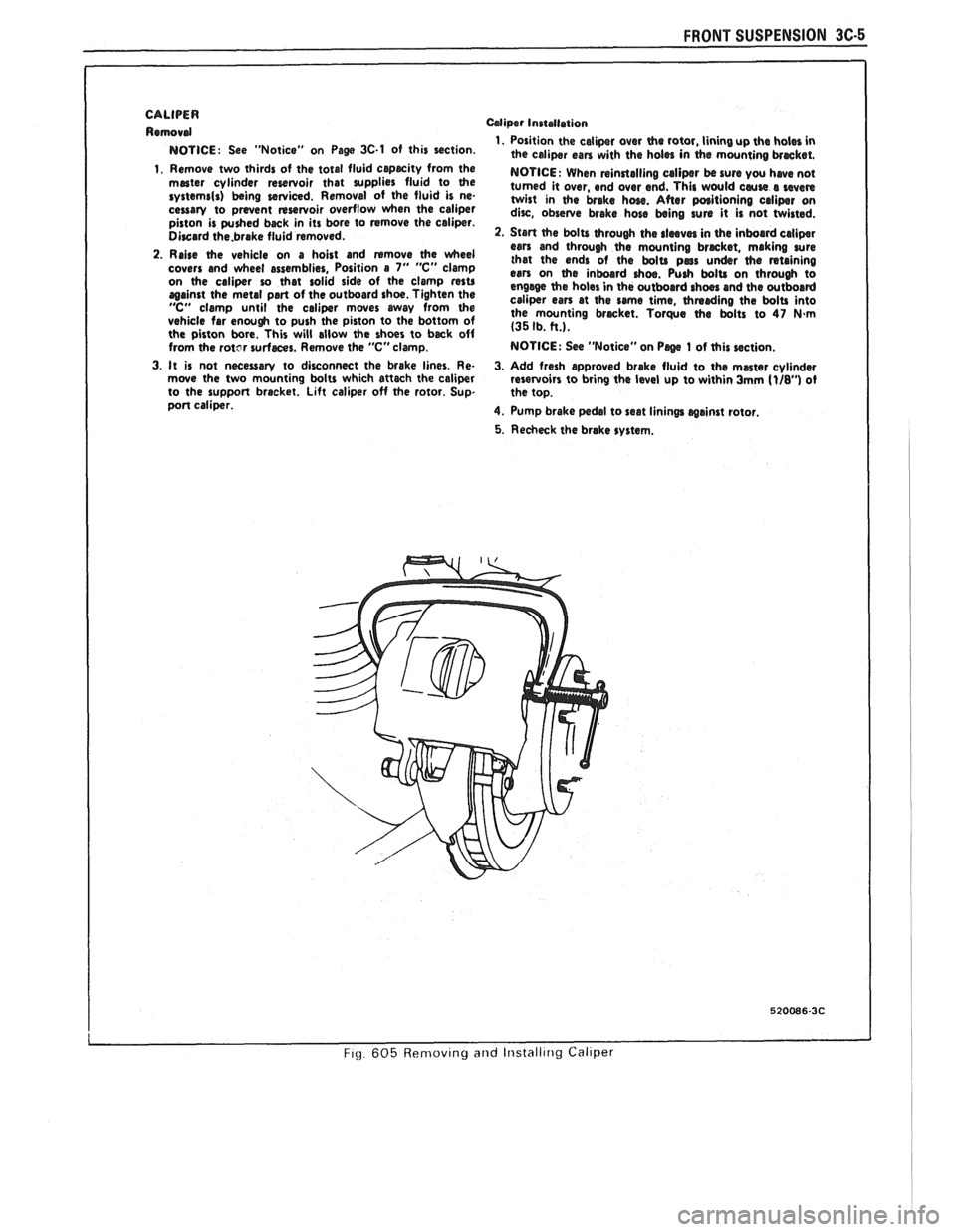
2. Raise the vehicle on a hoist and rumove (he wheel
covers and wheel assemblies, Position a 7" "C" clamp
on the caliper ro that solid side of the clamp resu against the metal part of the outboard shoe. Tighten the "C" clamp until the caliper mwes away from the vehicle far enough to push the piston to the bottom of
the piston bore. This will allow the shoes to back off
from the
rotcr surfaces. Remove the "C" clamp.
Mipr Installation
1. Position the caliper over the rotor, lining up the holes in
the caliper can with the holes in (he mounting brmket.
NOTICE: When rsinrtalling calipsr bc sure you hwe not
turned it over, end over end. This would cause s even twist in the brake hose. After poritioning caliper on dirc, observe brake hose being sun it is not twisted.
2. Start (he bolts through the rlmves in the inboard caliper ears and through the mounting brmket, making sure
that the ends of the bolts pars under (he rstaining esn on the inboard ohm. Push bolts on through to
engage the holes in the outboard rhm and the outboard
caliper ears at the same time, thmrding the bolts into
the mounting brwket. Torque the bolts to 47 N-m (35 Ib. tt.).
NOTICE: See "Notice" on Psge 1 of this section.
3. It
is not necessary to disconnect the brake lines. Re-
3. Add fresh approved brake fluid to the master cylinder
rnwe the two mounting bolts which attach the caliper
reservoirs to bring the level up to within 3mm [I/&') ot
to the support bracket. Lift caliper off the rotor. Sup.
the top.
port caliper.
4. Pump brake pedal to seat linings
wainst rotor.
5. Recheck the brake system.
I I
FI~ 605 Ren~ov~ng and Iristalltrig Callper
Page 235 of 1825
3E.4 TIRES AND WHEELS
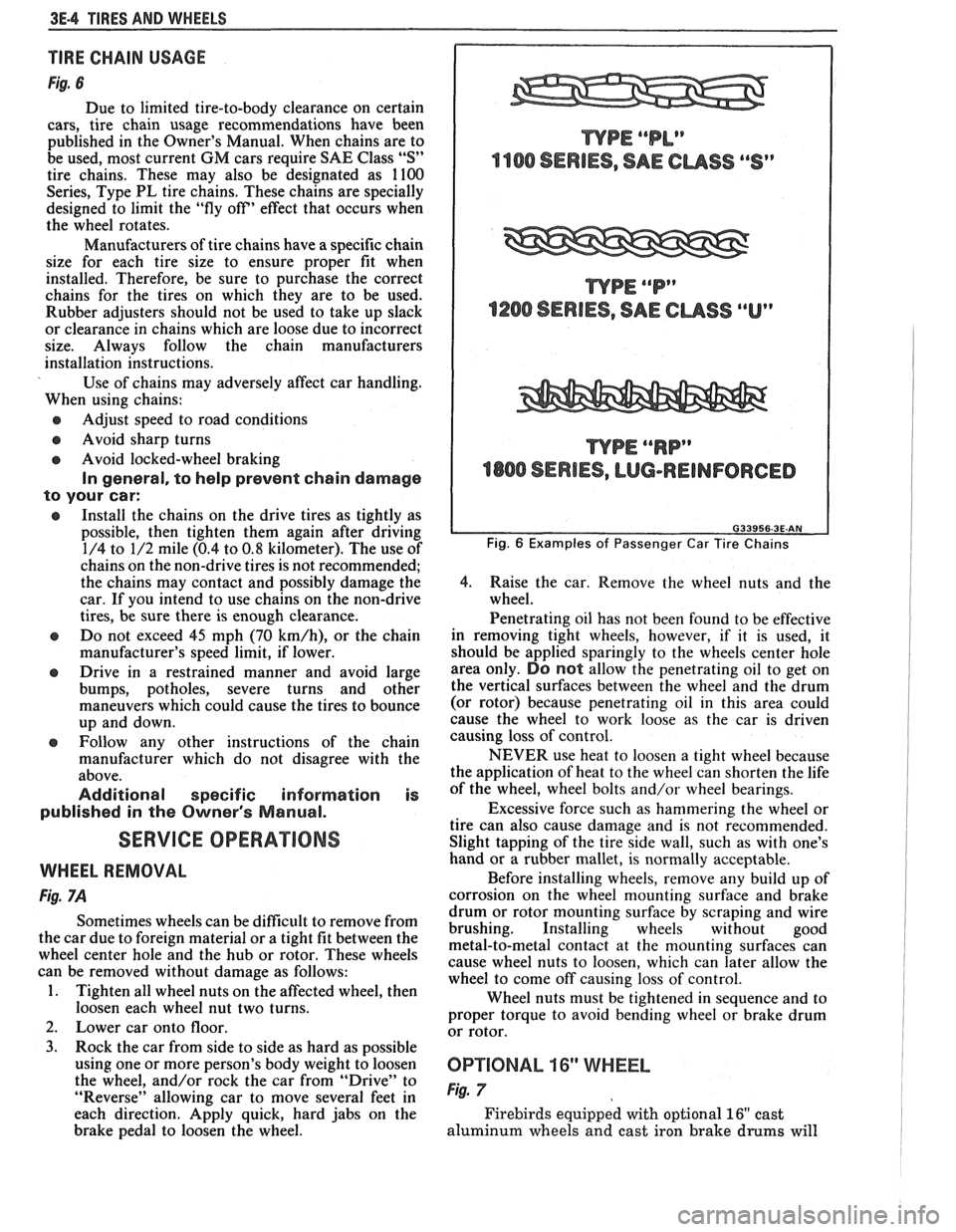
TIRE CHAIN USAGE
Fig. 6
Due to limited tire-to-body clearance on certain
cars, tire chain usage recommendations have been
published in the Owner's Manual. When chains are to
be used, most current
GM cars require SAE Class "S"
tire chains. These may also be designated as 1100
Series, Type PL tire chains. These chains are specially
designed to limit the "fly off' effect that occurs when
the wheel rotates.
Manufacturers of tire chains have a specific chain
size for each tire size to ensure proper fit when
installed. Therefore, be sure to purchase the correct
chains for the tires on which they are to be used.
Rubber adjusters should not be used to take up slack
or clearance in chains which are loose due to incorrect
size. Always follow the chain manufacturers
installation instructions.
Use of chains may adversely affect car handling.
When using chains:
@ Adjust speed to road conditions
@ Avoid sharp turns
@ Avoid locked-wheel braking
In general, to help prevent chain damage
to your car:
@ Install the chains on the drive tires as tightly as
possible, then tighten them again after driving
1/4 to 1/2 mile (0.4 to
0.8 kilometer). The use of
chains on the non-drive tires is not recommended;
the chains may contact and possibly damage the
car. If you intend to use chains on the non-drive
tires, be sure there is enough clearance.
e Do not exceed 45 mph (70 km/h), or the chain
manufacturer's speed limit, if lower.
@ Drive in a restrained manner and avoid large
bumps, potholes, severe turns and other
maneuvers which could cause the tires to bounce
up and down.
e Follow any other instructions of the chain
manufacturer which do not disagree with the
above.
Additional specific information is
published in the Owner's Manual.
SERVICE OPERATIONS
WHEEL REMOVAL
Fig. 7A
Sometimes wheels can be difficult to remove from
the car due to foreign material or a tight fit between the
wheel center hole and the hub or rotor. These wheels
can be removed without damage as follows:
1. Tighten all wheel nuts on the affected wheel, then
loosen each wheel nut two turns.
2. Lower car onto floor.
3. Rock the car from side to side as hard as possible
using one or more person's body weight to loosen
the wheel, and/or rock the car from
"Drive" to
"Reverse" allowing car to move several feet in
each direction. Apply quick, hard jabs on the
brake pedal to loosen the wheel.
WPE ""P"
1200 SERIES, SAE CUSS ""Up
WPE ""RP"
4800 SERIES, LUG-REINFORCED
Fig. 6 Examples of Passenger Car Tire Chains
4.
Raise the car. Remove the wheel nuts and the
wheel.
Penetrating oil has not been found to be effective
in removing tight wheels, however,
if it is used, it
should be applied sparingly to the wheels center hole
area only.
DO not allow the penetrating oil to get on
the vertical surfaces between the wheel and the drum
(or rotor) because penetrating oil in this area could
cause the wheel to work loose as the car is driven
causing loss of control.
NEVER use heat to loosen a tight wheel because
the application of heat to the wheel can shorten the life
of the wheel, wheel bolts and/or wheel bearings.
Excessive force such as hammering the wheel or
tire can also cause damage and is not recommended.
Slight tapping of the tire side wall, such as with one's
hand or a rubber mallet, is normally acceptable.
Before installing wheels, remove any build up of
corrosion on the wheel mounting surface and brake
drum or rotor mounting surface by scraping and wire
brushing. Installing wheels without good
metal-to-metal contact at the mounting surfaces can
cause wheel nuts to loosen, which can later allow the
wheel to come off causing loss of control.
Wheel nuts must be tightened in sequence and to
proper torque to avoid bending wheel or brake drum
or rotor.
0P"FIONAL 16" WHEEL
Fig. 7
Firebirds equipped with optional 16" cast
aluminum wheels and cast iron brake
drums will
Page 239 of 1825
3E-8 TIRES AND WHEELS
nearest the valve stem, and a 1/2 ounce balance weight
should be added 180" opposite the locking nut on the
wheel's inboard side.
When rotating tires, always re-install the locking
nut nearest the tire valve stem so that it remains
opposite the 1/2 ounce balance weight. This procedure
will improve the on-car wheel balance by compensating
for the heavy locking wheel nut.
Off-Car Balancing
Most electronic off-car balancers are more
accurate than the on-car spin balancers. They are easy
to use and give a dynamic (two plane) balance.
Although they do not correct for drum or rotor
unbalance as does on-car spin balancing, this is
overcome by their accuracy (usually to within 1/8
ounce). When balancing off-car, the wheel should
locate on the balancer with a cone through the back
side of the center pilot hole (not by the wheel stud
holes).
On-Car Balancing
When needed, on-car balancing will help correct
vibrations due to brake drum, rotor, and wheel cover
imbalance.
When balancing on car, do not remove the
balance weights from the off-car dynamic balance. If
more than one ounce of additional weight is required,
it should be split between the inner and outer rim
flange.
NOTICE: The driven tire and wheel assemblies
should be spun using the engine. Limit speed as
stated in the following Caution.
CAUTION: Do not spin the drive
wheels faster than
35 mph (55 km/h)
as indicated by the speedometer. This
limit is necessary because the
speedometer indicates only one-half
of the actual wheel speed when one
drive wheel is spinning and the other
drive wheel is stopped. Personal injury
and damage may result from high
speed spinning.
CAUTION: On cars equipped with
limited slip rear axles, do not attempt
to balance a tire on a
drive wheel with
the other drive wheel on the ground.
The car may drive through this wheel
and cause the car to move
unexpectedly, resulting in personal
injury and property damage.
To distinguish between standard rear axle and
limited slip, raise rear of car so both tires are clear of
ground. With the transmission in park (in gear with
manual transmission), attempt to turn one wheel by
hand. If the wheel can be turned, it is a standard rear
axle; if the wheel cannot be turned, it is a limited slip
rear axle. Also, check for Limited Slip
(G80) on Service
Parts Identification label.
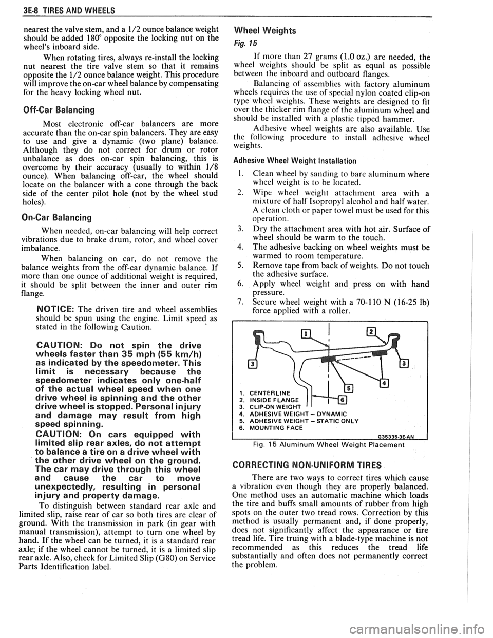
Wheel Weights
Fig. 15
If more than 27 grams (1.0 oz.) are needed, the
wheel weights should be split as equal as possible
between the inboard and outboard flanges.
Balancing of' assemblies with factory aluminum
wheels requires the use of special nylon coated clip-on
type wheel weights. These weights are designed to fit
over the thicker rim flange of the aluminum wheel and
should be installed with a plastic tipped hammer.
Adhesive wheel weights are also available. Use
the following procedure to install adhesive wheel
weights.
Adhesive Wheel Weight Installation
1. Clean wheel by sanding to bare aluminum where
wheel weight is to be located.
2. Wipe wheel weight attachment area with a
mixture of half Isopropyl alcohol and half water.
A clean cloth or paper towel niust be used for this
operat ion.
3. Dry the attachment area with hot air. Surface of
wheel should be warm to the touch.
4. The adhesive backing on wheel weights must be
warmed to room temperature.
5. Remove tape from back of weights. Do not touch
the adhesive surface.
6. Apply wheel weight and press on with hand
pressure.
7. Secure wheel weight with a 70-1 10
N (16-25 lb)
force applied with a roller.
CENTERLINE
1 INSIDE FLANGE CLIPBN WEIGHT 4. ADHESIVE WEIGHT - DYNAMIC 5. ADHESIVE WEIGHT -STATIC ONLY 6. MOUNTING FACE
Fig. 15 Aluminum Wheel Weight Placement
CORRECTING NON-UNIFORM TIRES
There are two ways to correct tires which cause
a vibration even though they are properly balanced.
One method uses an automatic machine which loads
the tire and buffs small amounts of rubber from high
spots on the outer two tread rows. Correction by this
method is usually permanent and, if done properly,
does not significantly affect the appearance or tire
tread life. Tire truing with a blade-type
machine is not
recommended as this reduces the tread life
substantially and often does not permanently correct
the problem.
Page 284 of 1825
REAR AXLE 48-1 1
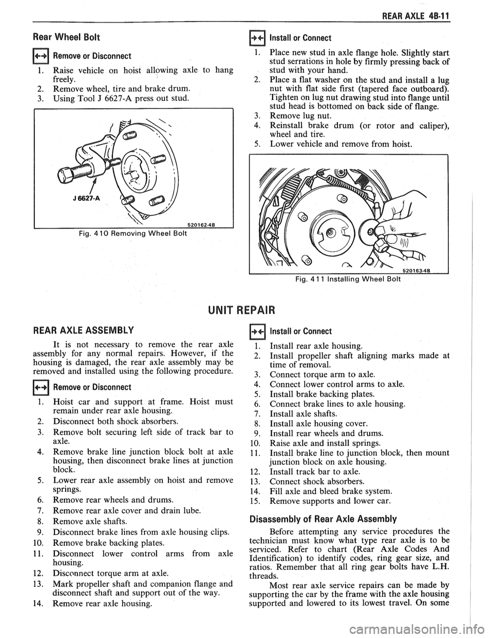
Rear Wheel Bolt
Remove or Disconnect 1.
1. Raise vehicle on hoist allowing axle to hang
freely. 2.
2. Remove
wheel, tire and brake drum.
3. Using Tool J 6627-A press out stud.
Fig. 4 10 Removing Wheel Bolt
REAR AXLE ASSEMBLY
Install or Connect
Fig. 4 11 Installing Wheel Bolt
UNIT REPAIR
Remove or Disconnect
Place new stud in axle flange hole. Slightly start
stud serrations in hole by firmly pressing back of
stud with your hand.
Place a flat washer on the stud and install a lug
nut with flat side first (tapered face outboard).
Tighten on lug nut drawing stud into flange until
stud head is bottomed on back side of flange.
Remove lug nut.
Reinstall brake drum (or rotor and caliper),
wheel and tire.
Lower vehicle and remove from hoist.
It is not necessary to remove the rear axle
assembly for any normal repairs. However, if the
housing is damaged, the rear axle assembly may be
removed and installed using the following procedure.
Hoist car and support at frame. Hoist must
remain under rear axle housing.
Disconnect both shock absorbers.
Remove bolt securing left side of track bar to
axle.
Remove brake line junction block bolt at axle
housing, then disconnect brake lines at junction
block.
Lower rear axle assembly on hoist and remove
springs.
Remove rear wheels and drums.
Remove rear axle cover and drain lube.
Remove axle shafts.
Disconnect brake lines from axle housing clips.
Remove brake backing plates.
Disconnect lower control arms from axle
housing.
Disconnect torque arm at axle.
Mark propeller shaft and companion flange and
disconnect shaft and support out of the way.
Remove rear axle housing.
Install or Connect
Install rear axle housing.
Install propeller shaft aligning marks made at
time of removal.
Connect torque arm to axle.
Connect lower control arms to axle.
Install brake backing plates.
Connect brake lines to axle housing.
Install axle shafts.
Install axle housing cover.
Install rear wheels and drums.
Raise axle and install springs.
Install brake line to junction block, then mount
junction block on axle housing.
Install track bar to axle.
Connect shock absorbers.
Fill axle and bleed brake system.
Remove supports and lower car.
Disassembly of Rear Axle Assembly
Before attempting any service procedures the
technician must know what type rear axle is to be
serviced. Refer to chart (Rear Axle Codes And
Identification) to identify codes, ring gear size, and
ratios. Remember that all ring gear bolts have L.H.
threads.
Most rear axle service repairs can be made by
supporting the car by the frame with the axle housing
supported and lowered to its lowest travel. On some
Page 294 of 1825
BRAKES
NOTICE: All brake attaching fasteners are important attaching parts in that they could affect the performance of vital parts
and systems.
andlor could result in major repair expense . They must be replaced with one of the same part number or with an
equivalent part if replacement becomes necessary
. Do not use a replacement part of lesser quality or substitute design .
Torque values must be used as specified during reassembly to assure proper retention of parts .
CAUTION: When servicing brake parts. do not create dust by grinding. sanding brake linings. or by cleaning brake
parts with a dry brush or with compressed air
. Many brake parts contain asbestos fibers which can become airborne if
dust is created during servicing
. Breathing dust containing asbestos fibers may cause serious bodily harm . A water
dampened cloth or water based solution should be used to remove any dust on brake parts
. Equipment is commer-
cially available to perform this washing function
. These wet methods will prevent asbestos fibers from becoming
airborne
.
CONTENTS
......................... General Description 5.2
Composite Master Cylinder
.................. 5.2
Brake Fluid Level
lndicatgr ................... 5.2
Operation of Disc Brake
..................... 5.2
Operation of Drum Brake
.................... 5.2
Operation of Combination Valve
............... 5.2
Brake Pressure Differential
.......................... Warning Switch 5.2
Diagnosis and Inspection ..................... 5.3
Brake System Testing
....................... 5.3
External Conditions That Affect Brake Performance
.................... -5-3
Warning Lamp Operation .................... 5.3
Brake Fluid Leaks
.......................... 5.3
Master Cylinder Check
...................... 5.3
Substandard or Contaminated
BrakeFluid ............................. 5-3
............................. On-Car Service 5.7
Brake Pedal Replacement
................... 5.7
Stoplamp Switch Adjustment ................. 5-7
Filling Master Cylinder Reservoirs
............. 5-7
Bleeding Brake Hydraulic System
............. 5.7
Manual Bleeding
......................... 5.8
Pressure Bleeding
........................ 5.8
Flushing Brake Hydraulic System
............. 5.9
Brake Pipe Replacement
.................... 5.9
............................. I.S.O. Flare 5.9
Brake Hose Inspection
...................... 5.9
Brake Hose Replacement
.................... 5.11
Front Brake Hose
........................ 5.11
....................... Center Brake Hose 5.12
..................... Rear Disc Brake Hose 5.12
ParkingBrake ............................. 5-13
Parking Brake Control Assembly
.............. 5.13 Parking Brake Cables
....................... 5.14
Parking Brake Front Cable
................. 5.14
Parking Brake Rear Cable (Drum Brakes)
..... 5.14
Parking Brake Rear Cable (Disc Brakes)
...... 5.15
Brake Lining Inspection
..................... 5.15
............. Inspecting and Refinishing Rotors 5-15
Thickness
Variat~on Check ................. 5.15
Lateral
Runout Check ..................... 5.15
Rotor Tolerance and Surface Finish
.......... 5.16
Refinishing Brake Rotors
.................. 5-16
lnspecting and Refinishing Brake
Drums
................................. 5-16
Cracked Scored, or Grooved Drum
.......... 5.16
Out-of-Round or Tapered Drum
............. 5.16
Refinishing Brake Drums
.................. 5.16
Brake Drum Balance
..................... -5-16
Combination Valve ......................... 5.17
Testing Combination Valve Electrical
............................... Circuit 5.17
Testing Combination Valve Warning
.......................... Lamp Switch 5.17
.......... Combination Valve Replacement 5.17
............ Power Brake Vacuum Hose Filter 5.17
Unit Repair
................ Composite Master Cylinder .5A 3.1
Disc Brake Caliper Assembly
....................... 300013100 Series 581 -1
Disc Brake Caliper Assembly
3548 Series
........................... .5B 6.1
........ Direct Torque Drum Brake Assembly .5C 3.1
Power Head Assembly
-
.................... Tandem Diaphragm .5D 2.1
.............. Specifications and Special Tools 5F-1
Page 295 of 1825
5-2 BRAKES
GENERAL DESCRIPTION
COMPOSIE EASTER CYLINDER
This vehicle uses a composite master cylinder which has
an aluminum body and a clear nylon reservoir with fluid
level indicators. The master cylinder uses a "quick take-up" feature in the
rear chamber to reduce pedal travel which may result from
increased fluid displacement required to move the caliper
piston. The quick take-up master cylinder includes a spring
loaded ball check valve which holds pressure in the
large-
diameter rear chamber. When the brake is first applied, the
movement of the rear piston causes fluid to be displaced
forward, past the primary piston primary seal and into the
primary high pressure chamber, which feeds the front
brakes. At a predetermined pressure, 480-690
kPa (70-100
mi), the ball unseats and fluid from the largi! rear bore is
disblaced past the ball and into the reservoir. The primary
and secondary high pressure chambers supply pressure to
the front and rear brakes, respectively, in the usual way.
When the pedal is released, the large-bore chamber is filled
with fluid by drawing fluid from the reservoir around the
quick take-up lip seal, and also through a small orifice in the
ball seat.
BRAKE FLUID LEVEL INDICATOR
(Figure 1)
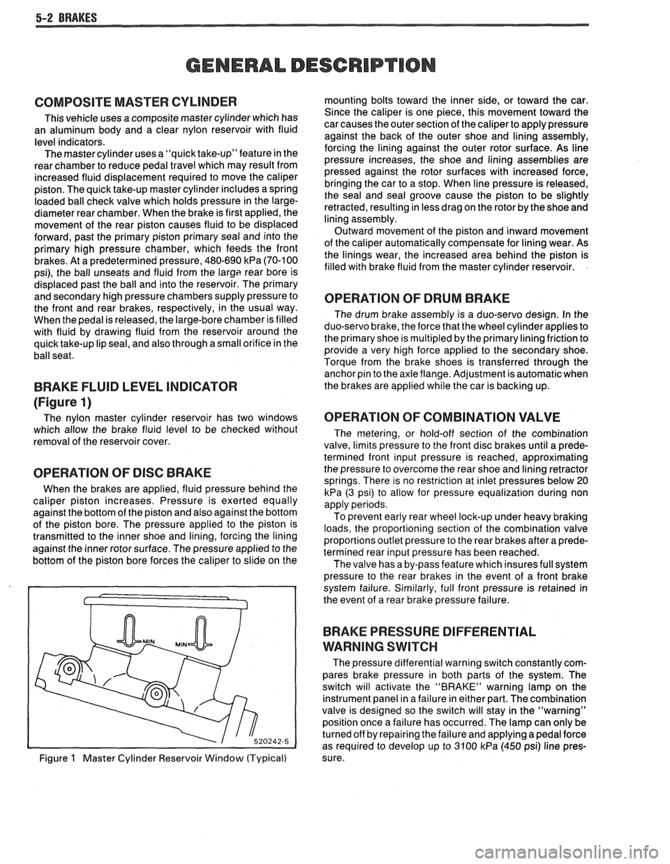
The nylon master cylinder reservoir has two windows
which allow the brake fluid level to be checked without
removal of the reservoir cover.
OPERATION OF DISC BRAKE
When the brakes are applied, fluid pressure behind the
caliper piston increases. Pressure is exerted equally
against the bottom of the piston and also against the bottom
of the piston bore. The pressure applied to the piston is
transmitted to the inner shoe and lining, forcing the lining
against the inner rotor surface. The pressure applied to the
bottom of the piston bore forces the caliper to slide on the
Figure
1 Master Cylinder Reservoir Window (Typical) mounting bolts toward the inner side,
or toward the car.
Since the caliper is one piece, this movement toward the
car causes the outer section of the caliper to apply pressure
against the back of the outer shoe and lining assembly,
forcing the lining against the outer rotor surface. As line
pressure increases, the shoe and lining assemblies are
pressed against the rotor surfaces with increased force,
bringing the car to a stop. When line pressure is released,
the seal and seal groove cause the piston to be slightly
retracted, resulting in less drag on the rotor by the shoe and
lining assembly.
Outward movement of the piston and inward movement
of the caliper automatically compensate for lining wear. As
the linings wear, the increased area behind the piston is
filled with brake fluid from the master cylinder reservoir.
OPERATION OF DRUM BRAKE
The drum brake assembly is a duo-servo design. In the
duo-servo brake, the force that the wheel cylinder applies to
the primary shoe is
multipled by the primary lining friction to
provide a very high force applied to the secondary shoe.
Torque from the brake shoes is transferred through the anchor pin to the axle flange. Adjustment is automatic when
the brakes are applied while the car is backing up.
OPERATION OF COMBINATION VALVE
The metering, or hold-off section of the combination
valve, limits pressure to the front disc brakes until a prede-
termined front input pressure is reached, approximating
the pressure to overcome the rear shoe and lining retractor
springs. There is no restriction at inlet pressures below 20
kPa (3 psi) to allow for pressure equalization during non
apply periods.
To prevent early rear wheel lock-up under heavy braking
loads, the proportioning section of the combination valve
proportions outlet pressure to the rear brakes after a prede-
termined rear input pressure has been reached.
The valve has a by-pass feature which insures full system
pressure to the rear brakes in the event of a front brake
system failure. Similarly, full front pressure is retained in
the event of a rear brake pressure failure.
BRAKE PRESSURE DIFFERENTIAL
WARNING
SWITCH
The pressure differential warning switch constantly com-
pares brake pressure in both parts of the system. The
switch will activate the "BRAKE" warning lamp on the
instrument panel in a failure in either part. The combination
valve is designed so the switch will stay in the "warning"
position once a failure has occurred. The lamp can only be
turned off by repairing the failure and applying a pedal force
as required to develop up to 3100
kPa (450 psi) line pres-
sure.