1988 PONTIAC FIERO auxiliary battery
[x] Cancel search: auxiliary batteryPage 447 of 1825

6D1-4 BATTERY
VOLTAGE
A. 16.0 or more
B. 14.0
- 15.9
C. 13.9 or less HOURS
1. Set parking brake and place automatic
Up to 4 Hours transmission in "PARK" (NEUTRAL for
Up to 8 Hours manual transmission.) Turn off the ignition,
Up to 16 Hours turn off lights, and all other electrical
If the charge current is still not
measurable
at the end of the above charging
times, the battery should be replaced.
If the charge current is measurable during
the charging time, the battery is considered to be
good and charging should be completed in the
normal manner.
5. It
is important to remember that a completely
discharged battery must be recharged for a
sufficient number of ampere hours (AH) to
restore it to a usable state. As a general rule of
thumb, using the reserve capacity rating (RC) of
the battery as the number of ampere hours of
charge will usually bring the green dot into view.
For example, if battery is rated at 75 RC minutes,
it would be completely recharged as follows:
10 ampere charge x 7-1/2 hours
= 75 AH
25 ampere charge x 3 hours = 75 AH, etc.
6. It
is recommended that any battery recharged by
this procedure be
LOAD TESTED to establish
serviceability.
JUMP STARTING IN CASE OF EMERGENCY
WITH AUXILIARY (BOOSTER) BAVEEWY
NOTICE: Do not push or tow the vehicle to start.
Damage to the emission system, or to other parts
of the vehicle may result.
Both booster and discharged battery should be
treated carefully when using jumper cables. Follow the
procedure outlined below, being careful not to cause
sparks:
CAUTION: Departure from these
conditions or the procedure below
could result in:
(1) Serious personal
injury (particularly to eyes) or property
damage from such causes as battery
explosion, battery acid, or electrical
burns; and/or
(2) damage to electronic
components of either vehicle.
Never expose battery to open flame or electric
spark
- batteries generate a gas which is flammable and
explosive.
Remove rings, watches, and other jewelry. Wear
approved eye protection.
Do not allow battery fluid to contact eyes, skin,
fabrics, or painted surfaces
- fluid is a corrosive acid.
Flush any contacted area with water immediately and
thoroughly. Be careful that metal tools or jumper
cables do not contact the positive battery terminal (or
metal in contact with it) and any other metal on the
car, because a short circuit could occur. Batteries
should always be kept out of the reach of children.
loads.
2. Check the built-in hydrometer. If it is clear or
light yellow, replace the battery.
3. Attach the end of one jumper cable to the positive
terminal of the booster battery and the other end
of the same cable to the positive terminal of the
discharged battery. Do not permit vehicles to
touch each other as this could cause a ground
connection and counteract the benefits of this
procedure. (Use 12-volt battery only to jump start
the engine).
4. Attach one end of the remaining negative cable
to the negative terminal of the booster battery,
and the other end to a solid engine ground (such
as
A/C compresser bracket or generator
mounting bracket) at least 18 inches from the
battery of the vehicle being started (DO NOT
CONNECT DIRECTLY TO THE NEGATIVE
TERMINAL OF THE DEAD BATTERY).
5. Start the engine of the vehicle that is providing
the jump start and turn off electrical accessories.
Then start the engine in the car with the
discharged battery.
6. Reverse these directions exactly when removing
the jumper cables. The negative cable must be
disconnected from the engine that was jump
started first.
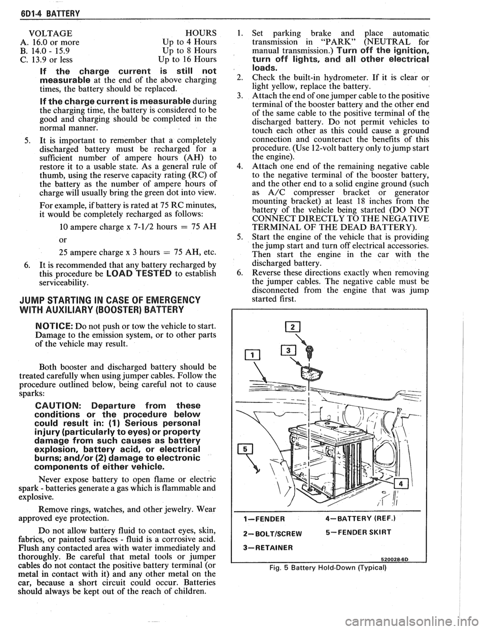
I-FENDER 4-BATTERY (REF.)
2- BOLTISCREW 5-FENDER SKIRT
3-RETAINER
520028-60
Fig. 5 Battery Hold-Down (Typical)
Page 1132 of 1825

AUTOMATIC TRANSMISSION ON-VEHICLE SERVICE 7A1-13
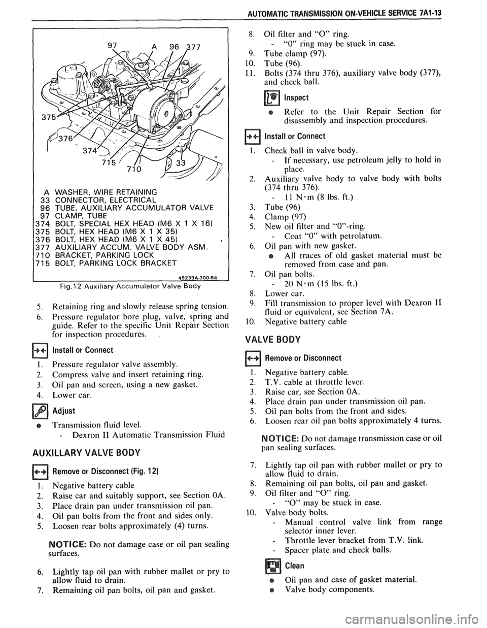
A WASHER, WIRE RETAINING
33 CONNECTOR, ELECTRICAL
96 TUBE, AUXILIARY ACCUMULATOR VALVE
97 CLAMP, TUBE
374 BOLT, SPECIAL HEX HEAD (M6
X 1 X 161
375 BOLT, HEX HEAD lM6
X 1 X 35)
376 BOLT, HEX HEAD lM6 X 1 X 45) , 377 AUXILIARY ACCUM. VALVE BODY ASM. 710 BRACKET, PARKING LOCK
71 5 BOLT, PARKING LOCK BRACKET
Fig. I2 Auxiliary Accumulator Valve Body
5. Retaining ring and slowly release spring tension.
6. Pressure regulator bore plug, valve, spring and
guide. Refer to the specific Unit Repair Section
for inspection procedures.
Install or Connect
1. Pressure regulator valve assembly.
2. Compress valve and insert retaining ring.
3. Oil pan
and screen, using a new gasket.
4. Lower car.
Adjust
cs Transmission fluid level.
- Dexron I1 Automatic Transmission Fluid
AUXILLARY VALVE BODY
Remove or Disconnect (Fig. 12)
I. Negative battery cable
2. Raise car and suitably support, see Section OA.
3. Place drain
pan under transmission oil pan.
4. Oil pan bolts from the front and sides only.
5. Loosen rear bolts approximately (4) turns.
NOTICE: Do not damage case or oil pan sealing
surfaces.
6. Lightly tap oil pan with rubber mallet or pry to
allow fluid to drain.
7. Remaining oil pan bolts, oil pan and gasket.
8. Oil filter and "0" ring.
- "0" ring may be stuck in case.
9. Tube clamp (97).
10. Tube (96).
11. Bolts (374 thru
376), auxiliary valve body (377),
and check ball.
Inspect
e Refer to the Unit Repair Section for
disassembly and inspection procedures.
Install or Connect
Check ball in valve body.
- If necessary, use petroleum jelly to hold in
place.
Auxiliary valve body to valve body with bolts
(374 thru 376).
- 11 N-rn(8lbs.ft.)
Tube (96)
Clamp (97)
New oil filter and "OW-ring.
- Coat "0" with petrolatum.
Oil pan with new gasket.
All traces of old gasket material must be
removed from case and pan.
Oil pan bolts.
- 20 Nem (15 Ibs. ft.)
Lower car.
Fill transmission to proper level with Dexron
I1
fluid or equivalent, see Section 7A.
Negative battery cable
VALVE BODY
Remove or Disconnect
1. Negative battery cable.
2. T.V. cable at throttle lever.
3. Raise car, see Section OA.
4. Place
drain pan under transmission oil pan.
5. Oil pan bolts from the front and sides.
6. Loosen
rear oil pan bolts approximately 4 turns.
NOTICE: Do not damage transmission case or oil
pan sealing surfaces.
7. Lightly
tap oil pan with rubber mallet or pry to
allow fluid to drain.
8. Remaining oil pan bolts, oil pan and gasket.
9. Oil
filter and
"0" ring.
- "0" may be stuck in case.
10. Valve body bolts.
- Manual control valve link from range
selector inner lever.
- Throttle lever bracket from T.V. link.
- Spacer plate and check balls.
Oil pan and case of gasket material.
e Valve body components.
Page 1309 of 1825

COOLANT FAN I g
TROUBLESHOOTING HINTS
@ Try the following checks before doing the Sys-
tem Check.
1. Check the CIH-FAN Fuse if the Coolant Fan
does not run.
2. Check that ground 6112 (V6 VIN S), 6117
(V8 VIN E) or 6104 (V8 VIN F and V8 VIN
8) is clean and tight.
3. Check the Fusible Link (see schematic).
4.
If the Coolant Fan runs with the Ignition
Switch OFF, replace the Coolant Fan Relay.
@ Go to System Check for a guide to normal
operation.
Go to System Diagnosis for diagnostic tests.
SYSTEM CHECK
Use the System Checlc Table as a guide to
normal operation.
SYSTEM CHECK TABLE
I ACTION I NORMALRESULT 1
COMPONENT LOCATION Page-Figure
Assembly Line Diagnostic Link
(ALDL) Connector .............. On bottom of IIP hush panel, to right of steering
column
Auxiliary Coolant Fan Relay
....... RH front side of engine compartment. ......... 201- 5-A
Auxiliary Coolant Fan Switch
...... Lower RN rear of engine .................... 201- 6-A
Coolant Fan Relay (VIN
E). ........ LH rear corner of engine compartment, on relay
bracket
................................. 201- 3-A
Coolant Fan Relay (VIN F) (VIN 8)
. . Front of engine compartment, RN side of
radiator support.
......................... 201- 5-A
Coolant Fan Relay (VIN S)
......... LH rear corner of engine compartment, on relay
................................. bracket 201- 0-A
Coolant Fan Switch
.............. Lower RH rear of engine, above starter solenoid . 201- 4-A
Coolant Temperature Sensor (VIN F)
(VIN 8).
....................... Top LW front of engine. ..................... 201- 8-C
Coolant Temperature Sensor (VIN S) Top LH front of intake manifold.
............. 201- 0-A
Electronic Control Module (ECM)
... Behind RN side of IIP ...................... 201-12-B
Fan Pressure Switch (VIN F) (VIN 8) Lower RH side of engine, on
AIC line .......... 201- 5-A
Fan Pressure Switch (VIN S)
....... Lower RN front of engine compartment, on AIC
line .................................... 201- 1-A
Fuse Block.
..................... Behind LN side of IIP, below light switch. ...... 201-10-A
Fusible Link
N (VIN E) ........... RH front of engine compartment, at Junction
Block ................................... 201- 3-B
Fusible Link N (VIN F) (VIN 8).
.... LN front of engine compartment, behind battery 201- 5-C
Fusible Link
J (VIN S) ............ RN side of radiator support, at Junction Block .. 201- 1-A
Redundant Cooling Fan Switch.
.... Top RW rear of engine ...................... 201- 1-6
C102 (4 cavities) ................. Center front of dash. ....................... 201-14-A
6104 (6 cavities)
................. Front of engine compartment, RH side of
................................ radiator. 201- 5-A
C204 (4 cavities) ................. Above LH rear corner of engine .............. 201- 0-A
C207 (15 cavities)
................ Behind RH side of IIP, near ECM ............. ,201-13-A
C224 (6 cavities) ................. Center of IIP, behind AIC control ............. 201-14-B
6104
.......................... On radiator support, behind RN headlights. .... 201-16-A
6112 (VIN E)
................... Rear of LN cylinder head. ................... 201- 3-C
6112 (VIN S)
.................... Rear of LH cylinder head. ................... 201- 0-C
6118 (VIN F) (VIN 8)
............. Rear of RH cylinder head. ................... 201- 5-A
6118 (VIN S)
.................... Rear of RH cylinder head. ................... 201- 1-C
(Continued on next page)
With
the engine cold
and idling, turn the
AIC Selector to
NORM (if equipped
with Ale)
VIN E: Coolant Fan
turns on
VIN S, VIN
F &
VIN 8: Coolant Fan
(and Auxiliary
Coolant Fan-if
equipped) turns on
when
A/C Control
Head Pressure
exceeds 233 psi
(1600
kPa)
(Continued on next page)