1988 PONTIAC FIERO window
[x] Cancel search: windowPage 24 of 1825
HEATING AND VENTILATION 1A-1
SECTION 1A
NG AND VENT
CONTENTS
General Description ................................. 1A-1
Diagnosis - Heater Trouble ...................... 1A-5
Insufficient Heating or Defrosting .............. 1A-5
Blower Electrical ......................................... 1A-7
....... Improper Air DeliveryINo Mode Shift 1 A-8
Too Much Heat .......................................... 1A-9 ....................................................... Controls 1A-10 ............................................... Blower Noise 1A-11
....................................... On-Vehicle Sewice 1A-13
.......................... Heater Control Assembly 1 A- 13
....................................... Blower Switch 1A- 13
.................................. Temperature Cable
1 A- 13
.......................................... Heater Core 1 A- 13
................................. Vent Control Cable 1 A- 13
Lower Heater Outlet
................................ 1A-14
........................................ Blower Motor 1A-14
GENERAL DESCRIPTION
The base heater system is designed to provide
heating, ventilation, windshield defrosting and on some
cars, side window defogging. Ram air ventilation is
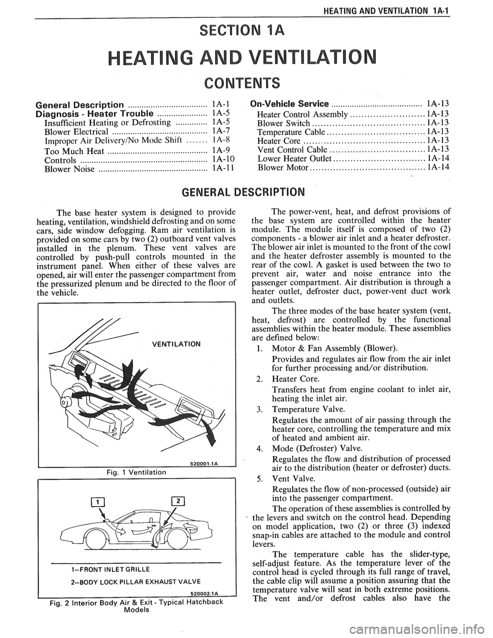
provided on some cars by two (2) outboard vent valves
installed in the plenum. These vent valves are
controlled by push-pull controls mounted in the
instrument panel. When either of these valves are
opened, air will enter the passenger compartment from
the pressurized plenum and be directed to the floor of
the vehicle.
/& VENTILATION
1-FRONT INLET GRILLE
2-BODY LOCK PILLAR EXHAUST VALVE
Fig. 2 Interior Body Air & Exit - Typical Hatchback Models
The power-vent, heat, and defrost provisions of
the base system are controlled within the heater
module. The module itself is composed of two (2)
components
- a blower air inlet and a heater defroster.
The blower air inlet is mounted to the front of the cowl
and the heater defroster assembly is mounted to the
rear of the cowl. A gasket is used between the two to
prevent air, water and noise entrance into the
passenger compartment. Air distribution is through a
heater outlet, defroster duct, power-vent duct work
and outlets.
The three modes of the base heater system (vent,
heat, defrost) are controlled by the functional
assemblies within the heater module. These assemblies
are defined below:
1. Motor & Fan Assembly (Blower).
Provides and regulates air flow from the air inlet
for further processing and/or distribution.
2. Heater Core.
Transfers heat from engine coolant to inlet air,
heating the inlet air.
3. Temperature Valve.
Regulates the amount of air passing through the
heater core, controlling the temperature and mix
of heated and ambient air.
4. Mode (Defroster) Valve.
Regulates the flow and distribution of processed
air to the distribution (heater or defroster) ducts.
5. Vent Valve.
Regulates the flow of non-processed (outside) air
into the passenger compartment.
The operation of these assemblies is controlled by
the levers and switch on the control head. Depending
on model application, two (2) or three
(3) indexed
snap-in cables are attached to the module and control
levers.
The temperature cable has the slider-type,
self-adjust feature. As the temperature lever of the
control head is cycled through its full range of travel,
the cable clip will assume a position assuring that the
temperature valve will seat in both extreme positions.
The vent and/or defrost cables also have the
Page 25 of 1825
1A-2 HEATING AND VENTILATION
520003-1 A
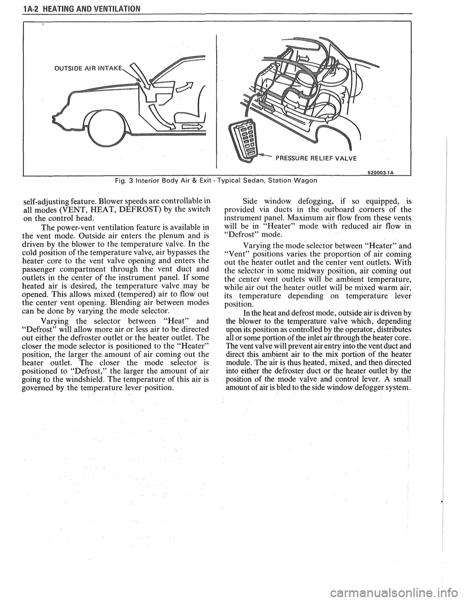
Fig. 3 Interior Body Air & Exit - Typical Sedan, Station Wagon
self-adjusting feature. Blower speeds are controllable in
all modes (VENT, HEAT, DEFROST) by the switch
on the control head.
The power-vent ventilation feature is available in
the vent mode. Outside air enters the plenum and is
driven by the blower to the temperature valve. In the
cold position of the temperature valve, air bypasses the
heater core to the vent valve opening and enters the
passenger compartment through the vent duct and
outlets
in the center of the instrument panel. If some
heated air is desired, the temperature valve may be
opened. This allows mixed (tempered) air to flow out
the center vent opening. Blending air between modes
can be done by varying the mode selector.
Varying the selector between "Heat" and
"Defrost" will allow more air or less air to be directed
out either the defroster outlet or the heater outlet. The
closer the mode selector is positioned to the "Heater"
position, the larger the amount of air coming out the
heater outlet. The closer the mode selector is
positioned to "Defrost," the larger the amount of air
going to the windshield. The temperature of this air is
governed by the temperature lever position. Side window
defogging, if so equipped, is
provided via ducts in the outboard corners of the
instrument panel. Maximum air flow from these vents
will be in "Heater" mode with reduced air flow in
"Defrost" mode.
Varying the mode selector between "Heater" and
"Vent" positions varies the proportion of air coming
out the heater outlet and the center vent outlets. With
the selector in some midway position, air coming out
the center vent outlets will be ambient temperature,
while air out the heater outlet will be mixed warm air,
its temperature depending on temperature lever
position.
In the heat and defrost mode, outside air is driven by
the blower to the temperature valve which, depending
upon its position as controlled by the operator, distributes
all or some portion of the inlet air through the heater core.
The vent valve will prevent air entry into the vent duct and
direct this ambient air to the mix portion of the heater
module. The air is thus heated, mixed, and then directed
into either the defroster duct or the heater outlet by the
position of the mode valve and control lever.
A small
amount of air is bled to the side window defogger system.
Page 26 of 1825
HEAPING AND VENTILA"T0N 1A-3
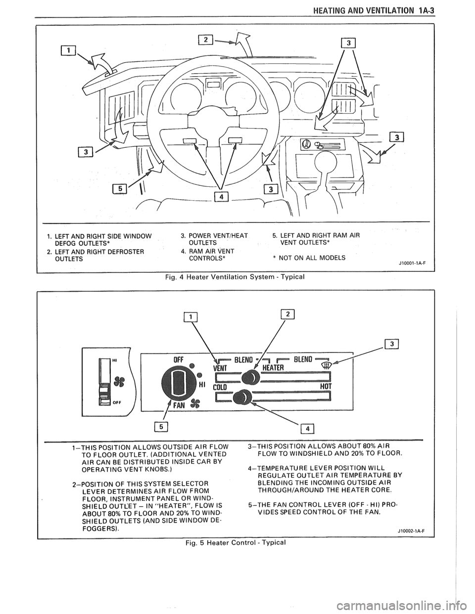
1, LEFT AND RIGHT SIDE WINDOW 3. POWER VENTIHEAT 5. LEFT AND RIGHT RAM AIR
DEFOG OUTLETS* OUTLETS VENT OUTLETS*
2. LEFT AND RIGHT DEFROSTER 4. RAM AIR VENT
OUTLETS CONTROLS* * NOT ON ALL MODELS J10001-1A-F
Fig. 4 Heater Ventilation System - Typical
1-THIS POSITION ALLOWS OUTSIDE AIR FLOW 3-THIS
POSITION ALLOWS ABOUT 80% AIR
TO FLOOR OUTLET. (ADDITIONAL VENTED FLOW
TO WINDSHIELD AND 20% TO FLOOR.
AIR CAN BE DISTRIBUTED INSIDE CAR BY
OPERATING VENT KNOBS.) 4-TEMPERATURE
LEVER POSITION WILL
REGULATE OUTLET AIR TEMPERATURE BY
2-POSITION OF
THIS SYSTEM SELECTOR BLENDING
THE INCOMING OUTSIDE AIR
LEVER DETERMINES AIR FLOW FROM THROUGHIAROUND THE HEATER CORE.
FLOOR, INSTRUMENT PANEL OR WIND-
SHIELD OUTLET - IN "HEATER", FLOW IS 5-THE
FAN CONTROL LEVER (OFF - HI) PRO.
ABOUT
80% TO FLOOR AND 20% TO WIND- VIBES SPEED CONTROL OF THE FAN.
SHIELD OUTLETS (AND
SlDE WINDOW DE-
FOGGERS).
Fig. 5 Heater Control - Typical
Page 27 of 1825
1A-4 HEATING AND VENTILATION
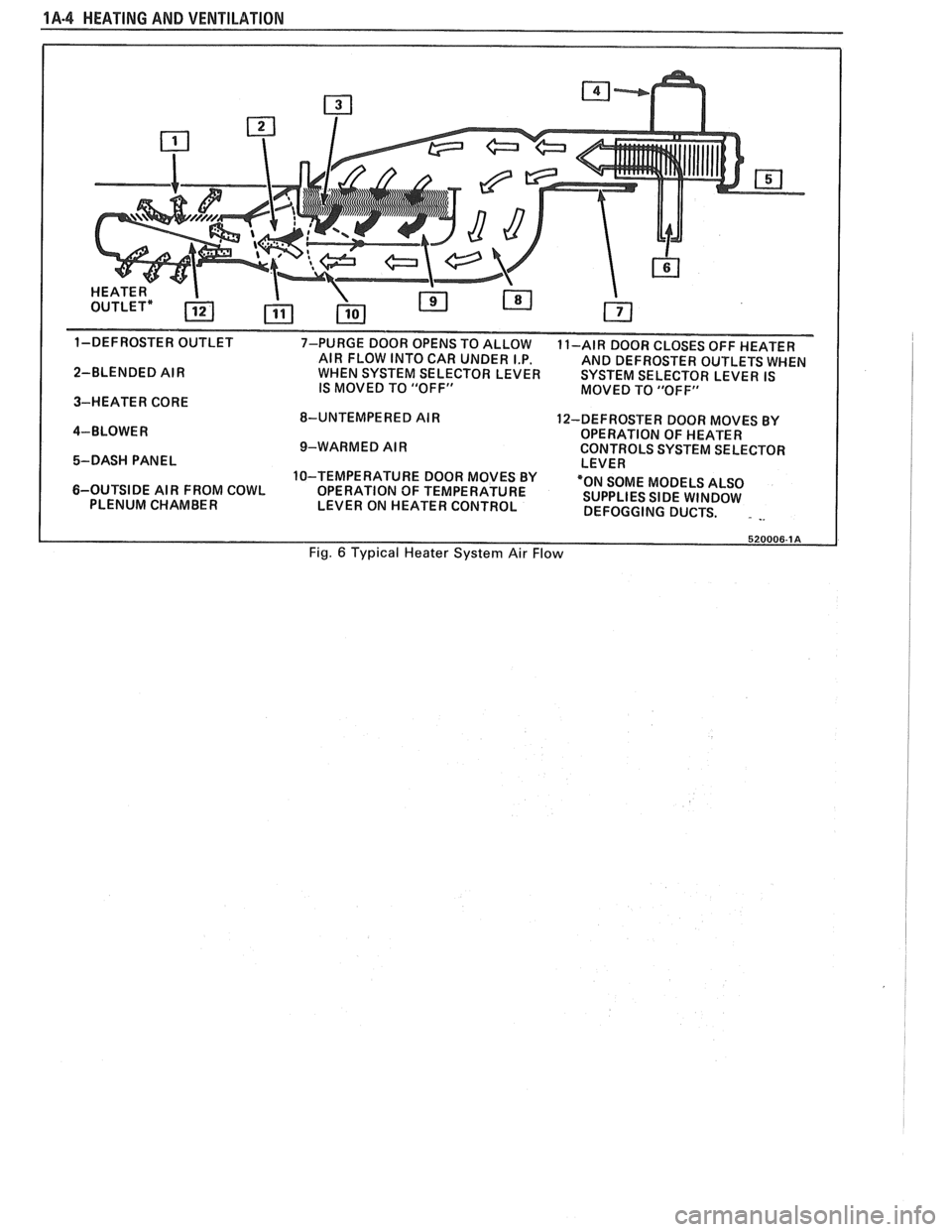
1-DEFROSTER OUTLET
7-PURGE DOOR OPENS TO ALLOW
11-AIR DOOR CLOSES OFF HEATER
AIR FLOW INTO CAR UNDER I.P.
AND DEFROSTER OUTLETS WHEN
2-BLENDED AIR WHEN SYSTEM SELECTOR LEVER SYSTEM SELECTOR LEVER IS
IS MOVED TO "OFF"
MOVED TO "OFF"
3-HEATER CORE
8-UNTEMPERED AIR
12-DEFROSTER DOOR MOVES BY
4-BLOWER OPERATION OF HEATER
9-WARMED AIR CONTROLS SYSTEM SELECTOR
5-DASH PANEL LEVER
10-TEMPERATURE DOOR MOVES BY
6-OUTSIDE AIR FROM COWL
OPERATION OF TEMPERATURE "ON
SOME MODELS ALSO
PLENUM CHAMBER
LEVER ON HEATER CONTROL SUPPLIES
SIDE WINDOW
DEFOGGING DUCTS.
. -.
Fig. 6 Typical Heater System Air Flow
Page 31 of 1825
1 A-8 HEATIN,G AND VENVILAVIBN
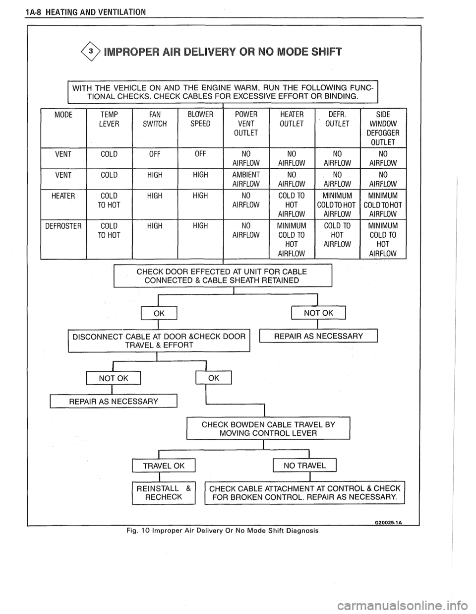
@ IMPROPER AIR DELIVERY OR NO MODE SHlFT
WITH THE VEHICLE ON AND THE ENGINE WARM, RUN THE FOLLOWING FUNC-
I TIONAL CHECKS. CHECK CABLES FOR EXCESSIVE EFFORT OR BINDING.
POWER VENT
OUTLET HEATER
OUTLET DEFR.
OUTLET
MODE
SIDE
WINDOW
DEFOGGER
OUTLET
VENT NO
AIRFLOW NO
AIRFLOW NO
AIRFLOW AIRFLOW
No I I I
COLD HIGH HIGH VENT AMBIENT
AIRFLOW NO
AIRFLOW NO
AIRFLOW AIRFLOW
No I
HEATER
DEFROSTER COLD HIGH HIGH
TO HOT
COLD
HIGH HIGH
TO HOT NO
AIRFLOW COLD
TO
HOT
AIRFLOW
MINIMUM COLD TO
HOT
AIRFLOW MINIMUM
COLDTO HOT
AIRFLOW
COLD TO
HOT
AIRFLOW MINIMUM
COLD TO HOT
AIRFLOW
MINIMUM COLD TO
AIRFLOW
N 0
AIRFLOW
CONNECTED
& CABLE SHEATH RETAINED
G20025.1A
Fig. 10 Improper Air Delivery Or No Mode Shift Diagnosis
Page 34 of 1825
HEATING AND VENTILATION 1 A-1 1
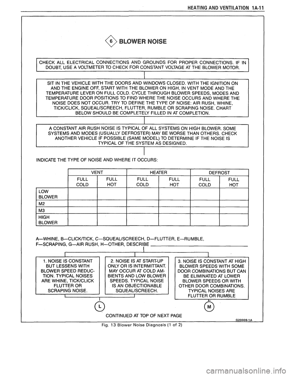
~ @ BLOWER NOISE
SIT IN THE VEHICLE WlTH THE DOORS AND WINDOWS CLOSED. WlTH THE IGNITION ON
AND THE ENGINE OFF, START WITH THE BLOWER ON HIGH, IN VENT MODE AND THE
TEMPERATURE LEVER ON FULL COLD. CYCLE THROUGH BLOWER SPEEDS, MODES AND
TEMPERATURE DOOR POSITIONS TO FIND WHERE THE NOISE OCCURS AND WHERE THE
SYSTEMS AND MODES (USUALLY DEFROSTER) MAY BE WORSE THAN OTHERS. CHECK
ANOTHER VEHICLE IF POSSIBLE (SAME MODEL) TO DETERMINE IF THE NOISE IS
TYPICAL OF THE SYSTEM AS DESIGNED.
INDICATE THE TYPE OF NOISE AND WHERE IT OCCURS:
A-WHINE,
B-CLICKTTICK, C-SQUEALISCREECH, D-FLUTTER, E-RUMBLE,
F-SCRAPING, G--AIR RUSH,
H-OTHER, DESCRIBE
I
BLOWER SPEED REDUC- MAY OCCUR AT COLD AM- DOOR COMBINATIONS BUT CAN
0
CONTINUED AT TOP OF NEXT PAGE G20009-1 A
Fig. 13 Blower Noise Diagnosis (1 of 2)
Page 49 of 1825
1B-6 AIR CONDlTlONlNC
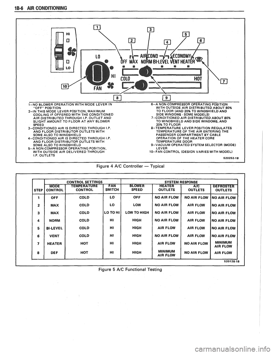
"OFF" POSITION WITH OUTSIDE AIR DISTRIBUTED ABOUT 80%
2-IN THIS MODE LEVER POSITION, MAXIMUM TO
FLOOR (AND 20% TO WINDSHIELD AND
COOLING IF OFFERED WITH THE CONDITIONED SIDE WINDOWS -SOME MODELS)
AIR DISTRIBUTED THROUGH I.P. OUTLET AND 7-CONDITIONED
AIR DISTRIBUTED ABOUT 80% SLIGHT AMOUNT TO FLOOR AT ANY BLOWER TO
WINDSHIELD AND SIDE WINDOWS, AND
20% TO FLOOR
3-CONDITIONED AIR IS DIRECTED THROUGH
I.P. 8-TEMPERATURE LEVER POSITION REGULATES
AND FLOOR DISTRIBUTOR OUTLETS WITH TEMPERATURE OF THE AIR ENTERING THE
SOME ALSO TO WINDSHIELD PASSENGER
COMPARTMENT BY CABLE
4-CONDITIONED AIR IS DIRECTED THROUGH
I.P. OPERATION OF THE HEATER CORE
AND FLOOR DISTRIBUTOR OUTLETS WITH TEMPERATURE DOOR
SOME ALSO TO WINDSHIELD 9-VACUUM
OPERATED SYSTEM SELECTOR (MODE)
5-A NON-COMPRESSOR OPERATING POSITION, LEVER
WITH OUTSIDE AIR DELIVERED THROUGH 10-FAN CONTROL
(DESIGN VARIES WITH MODEL) I.P. OUTLETS
Figure 4 AIC Controller -- Typical
Figure 5 A/C Functional Testing
Page 62 of 1825
AIR CONDITIONING 18-19
3. Push the tube into the fitting, bottoming it out.
Tighten
@ Torque nut to 15 Nam (11 lbs. ft.).
4. Dissasemble the joint.
5. Lubricate the
"0" ring with clean 525 viscosity
refrigerant oil.
6. Install the
"0" ring
on the tube. (See figure 17b)
7. Reassemble joint.
Tighten
@ Torque nut to 15 Nem (11 lbs. ft.).
8. Evacuate, charge, and leak test the system.
EXPANSlON "%BE (ORIFICE) SERVlCE
Remove or Disconnect
1. Discharge system.
2. Loosen fitting
at liquid line to evaporator inlet
pipe and remove tube carefully with needle
nosed pliers or Tool
5-26549-C or equivalent.
Install or Connect
1. Install
new orifice tube with shorter screen end
in first.
2. Install
liquid line and torque to proper
specification.
3. Evacuate and charge system.
In the event that difficulty is encountered during
the removal of a restricted or plugged expansion tube
(orifice tube), the following procedure is recom-
mended:
1. Remove
as much of any impacted residue as
possible.
2. Carefully apply heat with heat gun (hair drier,
epoxy drier or equivalent) approximately
114
inch from dimples on inlet pipe. Do not over-
heat pipe.
NOTICE: If the system has a pressure switch
near the orifice tube location, it should be
removed prior to heating the pipe to avoid dam-
age to switch.
3. While applying heat, use orifice removal tool
5-26549-C to grip the orifice tube. Use a turning
motion along with a push-pull motion to loosen
to the impacted orifice tube and remove it.
4. Swab inside of evaporator inlet pipe with R-11.
5, Add
1 oz. of 525 viscosity refrigerant oil to
system.
6. Lubricate new orifice tube and O-ring with 525'
viscosity refrigerant oil and insert into inlet
pipe. Install in proper direction (smaller screen
first).
ACCUMULATOR ASSEMBLY SERVICE
The accumulator assembly for the refrigerant
system has a service replacement which includes two
(2) O-rings (for the inlet and outlet connections). The
desiccant within the shell is NOT serviced separately
- it is part of the sealed accumulator assembly. See
REFRIGERANT OIL DISTRIBUTION for condi-
tions when the accumulator must be removed from the
vehicle to measure the amount of oil present inside the
accumulator.
The accumulator assembly should ONLY be
replaced when:
1. A physical perforation to the accumulator is
found, resulting in a leak.
2. If the system is open to air for an extended
period of time (due to a front-end collision,
removed parts, ect.). The desiccant bag will be
saturated with moisture.
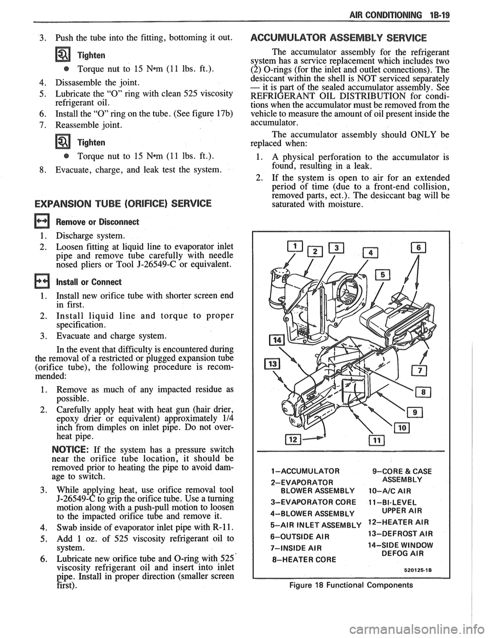
1 -ACCUMULATOR 9-CORE & CASE
2-EVAPORATOR BLOWER ASSEMBLY
10-A/C AIR
3-EVAPORATOR CORE 11-BI-LEVEL
4-BLOWER ASSEMBLY 5-AIR INLET ASSEMBLY
'IR
6-OUTSIDE AIR 13-DEFROST
AIR
7-INSIDE
AIR 14-SIDE WINDOW
DEFOG AIR
8-HEATER CORE
Figure 18 Functional Components