1988 PONTIAC FIERO steering wheel adjustment
[x] Cancel search: steering wheel adjustmentPage 21 of 1825
OB-4 MAINTENANCE AND LUBRICATION
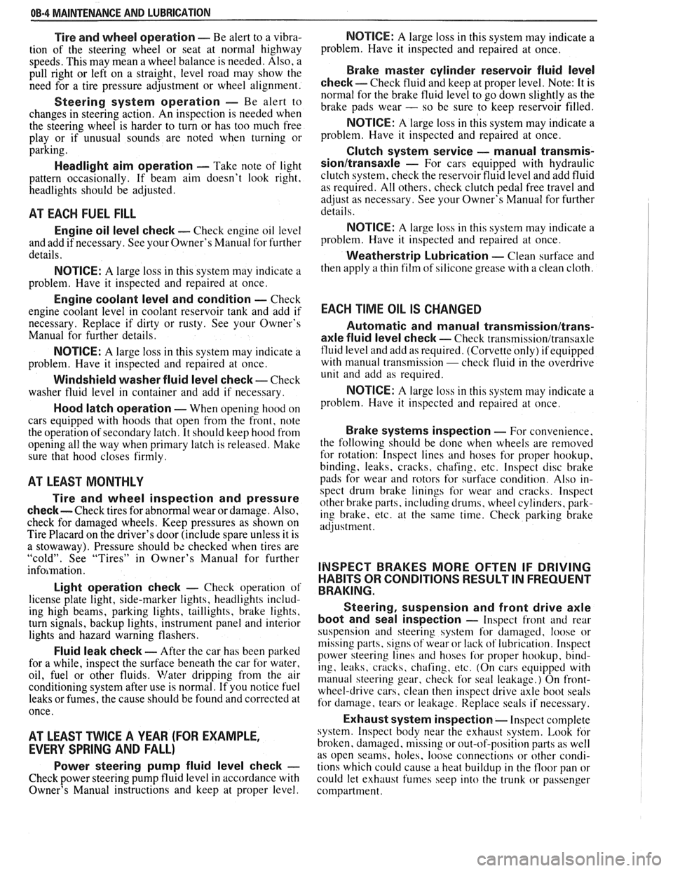
Tire and wheel operation - Be alert to a vibra-
tion of the steering wheel or seat at normal highway
speeds. This may mean a wheel balance is needed. Also, a
pull right or left on a straight, level road may show the
need for
a tire pressure adjustment or wheel alignment.
Steering system operation - Be alert to
changes in steering action. An inspection is needed when
the steering wheel is harder to turn or has too much free
play or if unusual sounds are noted when turning or
parking.
Headlight aim operation - Take note of light
pattern occasionally. If beam aim doesn't look right,
headlights should be adjusted.
AT EACH FUEL FILL
Engine oil level check - Check engine oil level
and add if necessary. See your Owner's
Manual for further
details.
NOTICE: A large loss in this system may indicate a
problem. Have it inspected and repaired at once.
Engine coolant level and condition - Check
engine coolant level in coolant reservoir tank and add if
necessary. Replace if dirty or rusty. See your Owner's
Manual for further details.
NOTICE: A large loss in this system may indicate a
problem. Have it inspected and repaired at once.
Windshield washer fluid level check -- Check
washer fluid level in container and add if necessary.
Hood latch operation - When opening hood on
cars equipped with hoods that open from the front, note
the operation of secondary latch. It should keep hood from
opening all the way when primary latch is released. Make
sure that hood closes firmly.
AT LEAST MONTI-ILY
Tire and wheel inspection and pressure
check--
Check tires for abnormal wear or damage. Also,
check for damaged wheels. Keep pressures as shown on
Tire Placard on the driver's door (include spare unless it is
a stowaway). Pressure should b\: checked when tires are
"cold". See "Tires" in Owner's Manual for further
infomation.
Light operation check - Check operation of
license plate light, side-marker lights, headlights includ-
ing high beams, parking lights, taillights, brake lights.
turn signals, backup lights, instrument panel and interior
lights and hazard warning flashers.
Fluid leak check - After the car has been parked
for a while, inspect the surface beneath the car for water,
oil, fuel or other fluids. Water dripping from the air
conditioning system after use is normal. If you notice fuel
leaks or fumes, the cause should be found and corrected at
once.
AT LEAST TWICE A YEAR (FOR EXAMPLE,
EVERY SPRING AND FALL)
Power steering pump fluid level check --
Check power steering pump fluid level in accordance with
Owner's Manual instructions and keep at proper level.
NOTICE: A large loss in this system may indicate a
problem. Have it inspected and repaired at once.
Brake master cylinder reservoir fluid level
check ---- Check fluid and keep at proper level. Note: It is
normal for the brake fluid level to go down slightly as the
brake pads wear
- so be sure to keep reservoir filled.
NOTICE: A large loss in this system may indicate a
problem. Have
it inspected and repaired at once.
Clutch system service --- manual transmis-
sionltransaxle --- For cars equipped with hydraulic
clutch system, check the reservoir fluid level and add fluid
as required. All others, check clutch pedal free travel and
adjust as necessary. See your Owner's Manual for further
details.
~
NOTICE: A large loss in this system may indicate a
problem. Have it inspected and repaired at once.
Weatherstrip Lubrication - Clean surface and
then apply a thin film of silicone grease with a clean cloth.
EACH TIME OIL IS CHANGED
Automatic and manual transmissionltrans-
axle fluid level check - Check transmission/transaxle
fluid level and add as required. (Corvette only) if equipped
with manual transmission
- check fluid in the overdrive
unit and add as required.
NOTICE: A large loss in this system may indicate a
problem. Have
it inspected and repaired at once.
Brake systems inspection - For convenience,
the following should be done when wheels are removed
for rotation: Inspect lines and hoses for proper hookup,
binding, leaks, cracks, chafing, etc. Inspect disc brake
pads for wear and rotors for surface condition. Also in-
spect drum brake linings for wear and cracks. Inspect
other brake parts, including drums, wheel cylinders, park-
ing brake, etc. at the same time. Check parking brake
adjustment.
INSPECT BRAKES MORE OFTEN IF DRIVING
HABITS OR CONDITIONS RESULT IN FREQUENT
BRAKING.
Steering, suspension and front drive axle
boot and seal inspection
- Inspect front and rear
suspension and steering system for damaged, loose or
missing parts, signs of wear or lack of lubrication. Inspect
power steering lines and hoses for proper hookup, bind-
ing, leaks, cracks, chafing, etc. (On cars equipped with
manual steering gear, check for seal leakage.) On
front-
wheel-drive cars, clean then inspect drive axle boot seals
for damage, tears or leakage. Replace seals if necessary.
Exhaust system inspection - Inspect complete
system. Inspect body near the exhaust system. Look for
broken, damaged, missing or out-of-position parts as well
as open seams, holes, loose connections or other condi-
tions which could cause a heat buildup in the tloor pan or
could let exhaust fumes seep into the trunk or passenger
compartment.
Page 127 of 1825
3-2 STEERING, SUSPENSION, TIRES AND WHEELS DIAGNOSIS
o Excessive wheel runout
e Blister or bump on tire
e Excessive loaded radial runout of tire and wheel
assembly
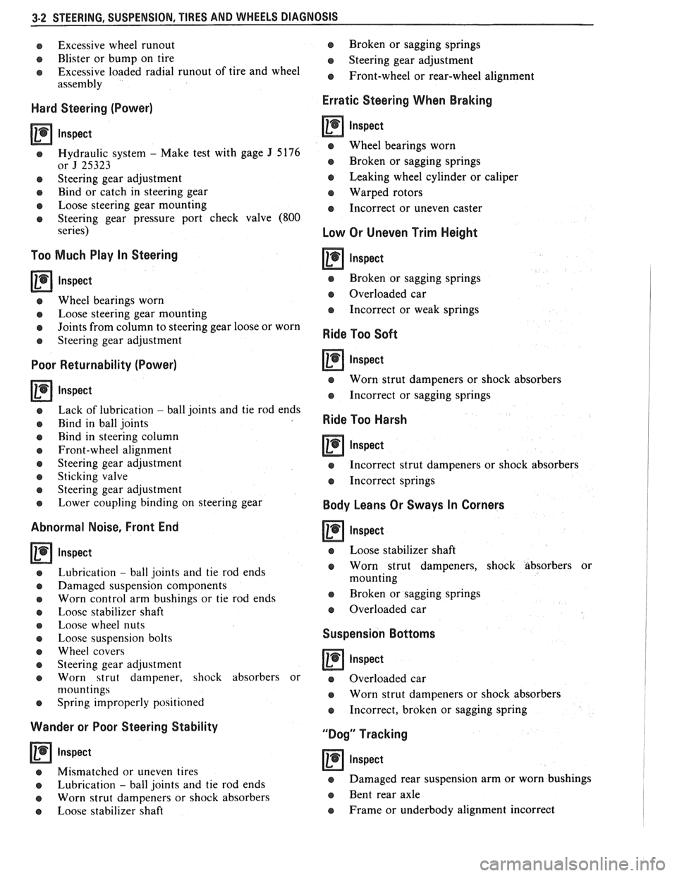
Hard Steering (Power)
lnspect
e Hydraulic system - Make test with gage J 5176
or J 25323
e Steering gear adjustment
e Bind or catch in steering gear
e Loose steering gear mounting
e Steering gear pressure port check valve (800
series)
Too Much Play In Steering
a lnspect
e Wheel bearings worn
e Loose steering gear mounting
e Joints from column to steering gear loose or worn
e Steering gear adjustment
Poor Returnability (Power)
Inspect
e Lack of lubrication - ball joints and tie rod ends
o Bind in ball joints
o Rind in steering column
e Front-wheel alignment
e Steering gear adjustment
e Sticking valve
o Steering gear adjustment
e Lower coupling binding on steering gear
Abnormal Noise, Front End
lnspect
Lubrication - ball joints and tie rod ends
Damaged suspension components
Worn control arm bushings or tie rod ends
Imose stabilizer shaft
Loose wheel nuts
Loose suspension bolts
Wheel covers
Steering gear adjustment
Worn strut dampener, shock absorbers or
n~ountings
Spring improperly positioned
Wander or Poor Steering Stability
Inspect
o Mismatched or uneven tires
e Lubrication - ball joints and tie rod ends
e Worn strut dampeners or shock absorbers
e Loose stabilizer shaft Broken
or sagging springs
e Steering gear adjustment
e Front-wheel or rear-wheel alignment
Erratic Steering When Braking
lnspect
e Wheel bearings worn
e Broken or sagging springs
e Leaking wheel cylinder or caliper
Warped rotors
e Incorrect or uneven caster
Low Or Uneven Trim Height
e Broken or sagging springs
@ Overloaded car
e Incorrect or weak springs
Ride Too Soft
Inspect
e Worn strut dampeners or shock absorbers
e Incorrect or sagging springs
Ride Too Harsh
lnspect -
e Incorrect strut dampeners or shock absorbers
e Incorrect springs
Body Leans Or Sways In Corners
lnspect
e Loose stabilizer shaft
e Worn strut dampeners, shock absorbers or
mounting
a Broken or sagging springs
e Overloaded car
Suspension Bottoms
lnspect
a Overloaded car
e Worn strut dampeners or shock absorbers
e Incorrect, broken or sagging spring
"Dog" Tracking
lnspect
e Damaged rear suspension arm or worn bushings
e Bent rear axle
e Frame or underbody alignment incorrect
Page 128 of 1825
STEERING, SUSPENSION, VIBES AND WHEELS DIAGNOSIS 3-3
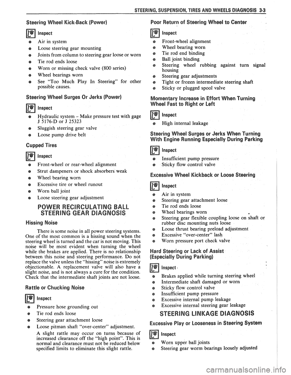
Steering Wheel Kick-Back (Power)
Inspect
e Air in system
e Loose steering gear mounting
e Joints from column to steering gear loose or worn
e Tie rod ends loose
Worn or missing check valve
(800 series)
e Wheel bearings worn
e See "Too Much Play In Steering" for other
possible causes.
Steering Wheel Surges Or Jerks (Power)
Inspect
Hydraulic system - Make pressure test with gage
J 5176-D or
J 25323
e Sluggish steering gear valve
Loose pump drive belt
Cupped Tires
Inspect
Front-wheel or rear-wheel alignment
e Strut dampeners or shock absorbers weak
e Wheel bearing worn
e Excessive tire or wheel runout
e Worn ball joint
a Loose steering gear adjustment
POWER RECIRCULATING BALL
SEERING GEAR DIAGNOSIS
Hissing Noise
There is some noise in all power steering systems.
One of the most common is a hissing sound when the
steering wheel is turned and the car is not moving. This
noise will be most evident when turning the wheel
while the brakes are applied. There is no relationship
between this noise and steering performance. Do not
replace the valve unless the "hissing" noise is extremely
objectionable. A replacement valve will also have a
slight noise, and is not always a cure for the condition.
Check that the intermediate shaft joints are not loose.
Rattle or Chucking Noise
Inspect -
Pressure hose grounding out
e Tie rod ends loose
e Steering gear attachment loose
a Loose pitman shaft "over-center" adjustment.
A slight rattle may occur on turns because of
increased clearance off the "high point". This is
normal and clearance must not be reduced below
specified limits to eliminate this slight rattle.
Poor Return of Steering Wheel to Center
Front-wheel alignment
Wheel bearing worn
Tie rod end binding
Ball joint binding
Steering wheel rubbing against turn signal
housing
Steering gear adjustments
Tight or frozen intermediate steering shaft
Sticky or plugged spool valve
Momentary Increase in Effort Whsn Turning
Wheel Fast to Right or Left
Inspect
High internal leakage
Steering Wheel Surges or Jerks When Turning
With
Engine Running Especially During Parking
ln8pe~t
e Insufficient pump pressure
Sticky flow control valve
Excessive Wheel Kickback or Loose Steering
Air in system
Steering gear attachment loose
Tie rod ends loose
Wheel bearings worn
Steering gear flexible coupling loose on shaft or
rubber disc mounting nuts loose
Loose thrust bearing preload adjustment
Excessive "over-center" lash
Worn pressure port check valve
Hard Steering or Lack of Assist
(Especially During Parking)
-
Brakes applied while turning steering wheel
Intermediate shaft damaged or worn
e Sticky flow control valve
Insufficient pump pressure
Excessive internal pump leakage
Excessive internal steering gear leakage
STEERING LINKAGE DIAGNOSIS
Excessive Play or Looseness in Steering Systern
inspect
r, Worn upper ball joints
e Steering gear worm bearings loosely adjusted
Page 129 of 1825
3.4 STEERING, SUSPENSION, TIRES AND WHEELS DIAGNOSIS
e Excessive pitman shaft to ball nut lash in steering
gear
e Worn intermediate rod or tie rod sockets
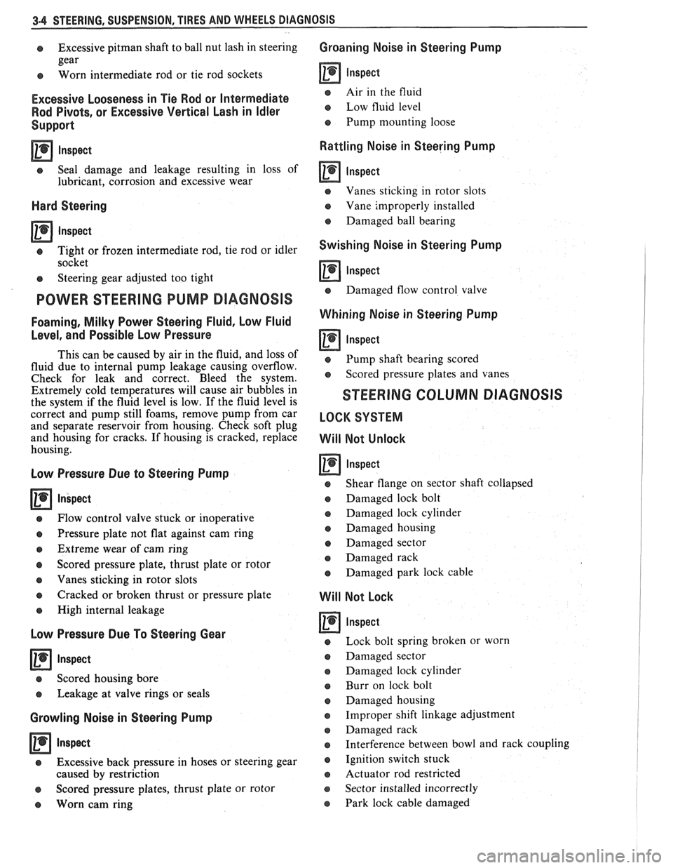
Excessive Looseness in Tie Rod or Intermediate
Rod Pivots, or Excessive Vertical Lash in
Idler
Support
Inspect -
e Seal damage and leakage resulting in loss of
lubricant, corrosion and excessive wear
Hard Steering
0 Inspect
e Tight or frozen intermediate rod, tie rod or idler
socket
e Steering gear adjusted too tight
POWER STEERING PUMP DIAGNOSIS
Foarning, Milky Power Steering Fluid, Low Fluid
Level, and Possible Low Pressure
This can be caused by air in the fluid, and loss of
fluid due to internal pump leakage causing overflow.
Check for leak and correct. Bleed the system.
Extremely cold temperatures will cause air bubbles in
the system if the fluid level is low. If the fluid level is
correct and pump still foams, remove pump from car
and separate reservoir from housing. Check soft plug
and housing for cracks. If housing is cracked, replace
housing.
Low Pressure Due to Steering Pump
Inspect
e Flow control valve stuck or inoperative
e Pressure plate not flat against cam ring
e Extreme wear of cam ring
e Scored pressure plate, thrust plate or rotor
e Vanes sticking in rotor slots
Q Cracked or broken thrust or pressure plate
e High internal leakage
Low Pressure Due To Steering Gear
Inspect
e Scored housing bore
Q Leakage at valve rings or seals
Growling Noise in Steering Pump
Inspect
e Excessive back pressure in hoses or steering gear
caused by restriction
e Scored pressure plates, thrust plate or rotor
e Worn cam ring
Groaning Noise in Steering Pump
Inspect
e Air in the fluid
Low fluid level
Q Pump mounting loose
Rattling Noise in Steering Pump
Inspect - -
e Vanes sticking in rotor slots
o Vane improperly installed
o Damaged ball bearing
Swishing Noise in Steering Pump
inspect
e Damaged flow control valve
Whining Noise in Steering Pump
Inspect
Q Pump shaft bearing scored
e Scored pressure plates and vanes
STEERING COLUMN DIAGNOSIS
LOCK SYSTEM
Will Not Unlock
Inspect
o Shear flange on sector shaft collapsed
Q Damaged lock bolt
e Damaged lock cylinder
o Damaged housing
e Damaged sector
e Damaged rack
e Damaged park lock cable
Will Not Lock
Inspect
Lock bolt spring broken or worn
Damaged sector
Damaged lock cylinder
Burr on lock bolt
Damaged housing
Improper shift linkage adjustment
Damaged rack
Interference between bowl and rack coupling
Ignition switch stuck
Actuator rod restricted
Sector installed incorrectly
Park lock cable damaged
Page 130 of 1825
STEERING. SUSPENSION. TIRES AND WHEELS DIAGNOSIS 3-5
High Lock Effort
rn lnspect
e Lock cylinder damaged
e Ignition switch damaged
o Rack preload spring broken or deformed
e Burrs on sector, rack, housing, support or
actuator rod coupling
,
e Bent sector shaft
e Damaged rack
e Extreme misalignment of' housing to cover
e Distorted coupling slot in rack
e Bent actuator rod
e Ignition switch mounting bracket bent
e Actuator rod restricted
e Improper shift linkage adjustment
Will Stick In "Start"
rn lnspect
e Actuator rod deformed
e Check items under "High Lock Effort"
Key Cannot Be Removed in "Off-Lock"
rn lnspect
e Ignition switch is not set correctly
e Damaged lock cylinder
e Linkage mis-adjusted
Lock Cylinder Can Be Removed
Inspect
e Lock cylinder retaining screw missing
High Effort In Lock Cylinder Between "Off" and
"Off-Lock"
lnspect
o Distorted rack
Lock Bolt Hits Shaft Lock In "Off" Position and
"Park"
lnspect
e Ignition switch is not set correctly
COLUMN
Noise In Column
Inspect
e Joints from the column to the steering gear 1
e Column not correctly aligned
e Horn contact ring not lubricated
e Lack of grease on bearings
o Loose sight shields
o Lower or upper steering shaft bearing worn or
broken
e Shaft lock snap ring not seated
o Spherical joint not lubricated
High Steering Shaft Effort
e Column assembly misaligned
e Improperly installed or deformed dust seal
e Damaged upper or lower bearing
e Flash on I.D. of shift tube
e Tight intermediate steering shaft universal joint
High Shift Effort (Automatic with Column Shift)
rn lnspect
e Column not aligned correctly in car
e Wave washer with burrs
e Improperly installed dust seal
o Lack of grease on seal or bearing
e Improper screws used for ignition switch
e Burr on upper or lower end of shift tube
e Lower bowl bearing not assembled correctly
Improper Shifting (Automatic with Column
Shift)
rn lnspect
e Sheared shift tube joint or lower shift lever weld
e Improper or loose linkage adjustment
e 1,oose shift lever
e Improper gate plate
Lash In Steering Column
lnspect
e 1.P.-to-column upper and lower bracket
nlounting bolts loose
e Broken weld nuts on jacket
e I.P. upper bracket capsule sheared
e Loose shoes in housing
e Loose tilt head pivot pins
e Loose shoe lock pin in support
e Loose support screws
e Column upper and lower bracket-to-jacket bolts
loose
e Loose lower bracket-to-adapter and bearing
assembly mounting screws
e Loose 1.P.-to-jacket mounting bolts
Housing Scraping On Bowl
rn Inspect
e Bowl bent or not concentric with hub
e Cover and housing end cap not properly installed
Page 135 of 1825

3-10 STEERING, SUSPENSION, TIRES AND WHEELS DIAGNOSIS
Reminder Keeps Operating With Key In Lock
Cylinder, Driver's Door Open Or Closed; Ceases
When Key Is Removed
Inspect
s Door jamb switch on driver's side misadjusted or
inoperative.
e Wire from signal switch to door jamb switch
shorted.
A. This condition indicates the lock cylinder or
the reminder switch is at fault. To verify,
check for continuity at the
"E" and "F"
male column connector contacts, with the
key removed from the lock cylinder. If
continuity exists, the fault is in the column.
B. Insert the key into the lock, then turn the
lock toward the "Start" position. If the
reminder stops when the key is in the
"Run" position or when it is turned past
"Run" toward "Start," the problem is a
sticky lock cylinder actuator.
COLUMN-MOUNTED DIMMER SWITCH
No "Low" or "High" Beam
Inspect
e Loose connector at dimmer switch
e Improper adjustment
e Internally damaged or worn switch. Check the
continuity on the switch at the It. green and at the
tan switch terminals by pushing in the plunger all
the way.
A click should be heard. If there is no
continuity, replace the dimmer switch. If there is
continuity, refer
to'section 8A for electricaldiag-
nosis.
PIVOT AND SWITCH ASSEMBLY
Switch Inoperative: No "Low," "High" and/or
"Wash"
e Loose body-to-switch connector
a Broken or damaged switch
Internally damaged or worn switch. Connect a
new switch without removing the old one. If the
system functions, replace the switch. If the
system doesn't function, refer to Section
8A for
electrical diagnosis.
STEERING GEAR AND PUMP LEAKS
General Procedure
Inspect
s Overfilled reservoir
s Fluid aeration and overflow
e , Hose connections
Verify exact point of leakage Example:
Torsion bar, stub shaft and
adjuster seals are close together; the exact
spot where the system is leaking may not be
clear.
Example: The point from which the fluid is
dripping is not necessarily the point where
the system is leaking; fluid overflowing from
the reservoir, for instance.
e When service is required:
A. Clean leakage area upon disassembly.
B. Replace leaking seal.
C. Check component sealing surfaces for
damage.
D. Reset bolt torque to specifications, where
required.
Some complaints about the power steering system
may be reported as:
A. Fluid leakage on garage floor
B. Fluid leaks visible on steering gear or pump
C. Growling noise, especially when parking or
when engine is cold
D. Loss of power steering when parking
E. Heavy steering effort
When troubleshooting these kinds of complaints,
check for an external leak in the power steering system.
For further diagnosis of leaks, refer to External
Leakage Check in this section.
External Leakage Check
Fig. 12
The purpose of this procedure is to pinpoint the
location of the leak.
In some cases, the leak can easily be located. But,
seepage-type leaks may be more difficult to isolate. To
locate seepage leaks, use the following method.
1. With the engine off, wipe dry the complete power
steering system.
2. Check the fluid level in the pump's reservoir. Add
fluid if necessary.
3. Start the engine, then turn the steering wheel
from stop to stop several times. Do not hold it at
a stop for any length of time, as this can damage
the power steering pump. It is easier if someone
else operates the steering wheel while you search
for the seepage.
4. Find the exact area of the leak and repair leak.
SEAL REPLACEMENT
RECOMMENDATIONS
Lip seals, which seal rotating shafts, require
special treatment. This type of seal is used on the
steering gear and on the drive shaft of the pump. When
there is a leak in one of these areas, always replace the
seal(s), after inspecting and thoroughly cleaning the
sealing surfaces. Replace the shaft only if very severe
pitting is found. If the corrosion in the lip seal contact
zone is slight, clean the surface of the shaft with crocus
cloth. Replace the shaft only if the leakage cannot be
stopped by first smoothing with crocus cloth.
Page 139 of 1825
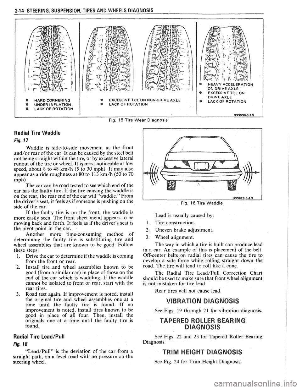
3-14 STEERING, SUSPENSION, TIRES AND WHEELS DIAGNOSIS
@ HARD CORNERING O UNDER INFLATION LACK OF ROTATION
@ HEAVY ACCELERATION ON DRIVE AXLE EXCESSIVE TOE ON DRIVE AXLE EXCESSIVE TOE ON NON-DRIVE AXLE @ LACK OF ROTATION O LACK. OF ROTAT ION
Fig. 15 Tire Wear Diagnosis
Radial Tire Waddle
Fig. 17
Waddle is side-to-side movement at the front
and/or rear of the car. It can be caused by the steel belt
not being straight within the tire, or by excessive lateral
runout of the tire or wheel. It ig most noticeable at low
speed, about 8 to 48
km/h (5 to 30 mph). It may also
appear as a ride roughness at 80 to 113
km/h (50 to 70
mph). The car can be road tested to see which end of the
car has the faulty tire. If the tire causing the waddle is
on the rear, the rear end of the car will "waddle." From
the driver's seat, it feels as if someone is pushing on the
side of the car.
If the faulty tire is on the front, the waddle is
more easily seen. The front sheet metal appears to be
moving back and forth. It feels as if the driver's seat is
the pivot point in the car.
Another more time-consuming method of
determining the faulty tire is substituting tire and
wheel assemblies that are known to be good. Follow
these steps:
1. Drive the car to determine if the waddle is coming
from the front or rear.
2. Install tire and wheel assemblies known to be
good (from a similar car) in place of those on the
end of the car which is waddling. If the waddle
cannot be isolated to front or rear, start with the
rear tires.
3. Road test again. If improvement is noted, install
the original tire and wheel assemblies one at a
time until the faulty tire is found. If no
improvement is noted, install tires known to be
good in place of all four. Then, install the
originals one at a time until the faulty tire is
found.
Radial Tire Lead/Pull
Fig. 18
"Lead/Pull" is the deviation of the car from a
straight path, on a level road with no pressure
on the
steering wheel.
L Fig. 16 Tire Waddle
Lead is usually caused by:
1. Tire construction.
2. Uneven brake adjustment.
3. Wheel alignment.
The way in which a tire is built can produce lead
in a car. An example of this is placement of the belt.
Off-center belts on radial tires can cause the tire to
develop a side force while rolling straight down the
road. The tire will tend to roll like a cone.
The Radial Tire
Lead/Pull Correction Chart
should be used to make sure that front wheel alignment
is not mistaken for tire lead.
Rear tires will not cause lead.
VIBRATION DIAGNOSIS
See Figs. 19 through 21 for vibration diagnosis.
TAPERED ROLLER BEARING
DlAGNOSlS
See Figs. 22 and 23 for Tapered Roller Bearing
Diagnosis.
See Fig. 24 for Trim Height Diagnosis.
Page 148 of 1825
-
WHEEL. ALIGNMENT 3A-1
SECTION 3A
WHEEL AL GNMENT
NOTICE: These fasteners are important attaching Do not use a replacement part of lesser quality or
parts, in that they could affect the performance of substitute
design. Torque values must be used as
vital components and systems, and/or could result specified during reassembly to assure proper
in major repair expense. They must be replaced retention of these parts. For prevailing torque
with one of the same part number or with an
nut(s) and bolt(s), refer to the "Reuse of Prevailing
equivalent part if replacement becomes necessary. torque
Nut(s) and Bolt(s)" chart in Section 0.
General Description ...................... .. ...... 3A- 1 On-Car Service ........................ .. ........... 3A-2
Caster .................... .. ............................ 3A- 1 Caster and Camber Adjustment .................. 3A-2
..................................... Camber ................... .. .............................. 3A-I Toe-In Adjustment 3A-2
Toe.. ................................................. 3A- 1 Axle Housing Alignment ......................... .... 3A-4
Preliminary Checks Prior to Specifications ....................... ... ............... 3A-4
Adjusting Alignment ..................... ...... 3A- 1
GENERAL DESCRIPmIOMI
Wheel alignment refers to the angular they tend to roll parallel on the road when the car is
relationship between the wheels, the suspension moving.
attaching parts and the ground.
PRELIMINARY CHECKS PRIOR TO ADJUSTING
CASTER ALIGNMENT
Figure 1
Caster is the amount the top of the strut is tilted
forward or rearward from the vertical. When the strut
tilts rearward, the center is "positive"
(+). The
amount of tilt is measured in degrees from vertical.
CAMBER
Figure 1
Camber is the tilting of the wheels from the
vertical when viewed from the front of the car. When
the wheels tilt outward at the top, the camber is said
to be positive
(+). When the wheels tilt inward at the
top, the camber is said to be negative
(-). The amount
of tilt is measured in degrees from the vertical and this
measurement is called the camber angle.
TOE
Figure i
Toe is a measurement of how much the front of
the wheels are turned in or out from a straight-ahead
position. When the wheels are turned in, toe is
"positive"
(+). When the wheels are turned out, toe
is "negative"
(-). The actual amount of toe-in is
normally only a fraction of a degree. The purpose of a
toe specification is to ensure parallel rolling of the
wheels (excessive toe-in or toe-out may increase tire
wear). Toe also serves to offset the small deflections of
the wheel support system which occur when the car is
rolling forward. In other words, even when the wheels
are set to toe-in slightly when the car is standing still, Steering
and vibration complaints are not always
the result of improper alignment. Another possibility
is tire "lead" due to worn or improperly manufactured
tires. "Lead" is the deviation of the car from a straight
path on a level road without hand pressure on the
steering wheel. Section
3 of this manual contains a
procedure for determining the presence of a tire lead
problem.
Before making any adjustment affecting wheel
alignment, make the following checks to ensure correct
alignment readings and alignment adjustments:
1. Check all tires for proper inflation pressures and
approximately the same tread wear.
2. Hub and bearing assemblies for excessive wear;
correct if necessary.
3. Ball joints and tie rod ends; if they are excessively
lcose, correct them before adjusting.
4. Run-out of wheels and tires.
5. Car trim height; if out of limits and a correction
is to be made, do so before adjusting alignment.
Refer to Section
3 for trim height specifications.
6. Strut dampeners for proper operation.
7. Control arms for loose bushings.
8. Loose or missing stabilizer bar attachments.
Consideration must be given to excess loads, such
as tool boxes, sample cases, etc. If these items are
normally carried in the car, they should remain in the
car during alignment adjustments. Consideration
should also be given to the condition of the equipment
used to adjust alignment. Be sure to follow the
equipment manufacturer's instructions. Regardless
of