1988 PONTIAC FIERO high beam
[x] Cancel search: high beamPage 21 of 1825
OB-4 MAINTENANCE AND LUBRICATION
Tire and wheel operation - Be alert to a vibra-
tion of the steering wheel or seat at normal highway
speeds. This may mean a wheel balance is needed. Also, a
pull right or left on a straight, level road may show the
need for
a tire pressure adjustment or wheel alignment.
Steering system operation - Be alert to
changes in steering action. An inspection is needed when
the steering wheel is harder to turn or has too much free
play or if unusual sounds are noted when turning or
parking.
Headlight aim operation - Take note of light
pattern occasionally. If beam aim doesn't look right,
headlights should be adjusted.
AT EACH FUEL FILL
Engine oil level check - Check engine oil level
and add if necessary. See your Owner's
Manual for further
details.
NOTICE: A large loss in this system may indicate a
problem. Have it inspected and repaired at once.
Engine coolant level and condition - Check
engine coolant level in coolant reservoir tank and add if
necessary. Replace if dirty or rusty. See your Owner's
Manual for further details.
NOTICE: A large loss in this system may indicate a
problem. Have it inspected and repaired at once.
Windshield washer fluid level check -- Check
washer fluid level in container and add if necessary.
Hood latch operation - When opening hood on
cars equipped with hoods that open from the front, note
the operation of secondary latch. It should keep hood from
opening all the way when primary latch is released. Make
sure that hood closes firmly.
AT LEAST MONTI-ILY
Tire and wheel inspection and pressure
check--
Check tires for abnormal wear or damage. Also,
check for damaged wheels. Keep pressures as shown on
Tire Placard on the driver's door (include spare unless it is
a stowaway). Pressure should b\: checked when tires are
"cold". See "Tires" in Owner's Manual for further
infomation.
Light operation check - Check operation of
license plate light, side-marker lights, headlights includ-
ing high beams, parking lights, taillights, brake lights.
turn signals, backup lights, instrument panel and interior
lights and hazard warning flashers.
Fluid leak check - After the car has been parked
for a while, inspect the surface beneath the car for water,
oil, fuel or other fluids. Water dripping from the air
conditioning system after use is normal. If you notice fuel
leaks or fumes, the cause should be found and corrected at
once.
AT LEAST TWICE A YEAR (FOR EXAMPLE,
EVERY SPRING AND FALL)
Power steering pump fluid level check --
Check power steering pump fluid level in accordance with
Owner's Manual instructions and keep at proper level.
NOTICE: A large loss in this system may indicate a
problem. Have it inspected and repaired at once.
Brake master cylinder reservoir fluid level
check ---- Check fluid and keep at proper level. Note: It is
normal for the brake fluid level to go down slightly as the
brake pads wear
- so be sure to keep reservoir filled.
NOTICE: A large loss in this system may indicate a
problem. Have
it inspected and repaired at once.
Clutch system service --- manual transmis-
sionltransaxle --- For cars equipped with hydraulic
clutch system, check the reservoir fluid level and add fluid
as required. All others, check clutch pedal free travel and
adjust as necessary. See your Owner's Manual for further
details.
~
NOTICE: A large loss in this system may indicate a
problem. Have it inspected and repaired at once.
Weatherstrip Lubrication - Clean surface and
then apply a thin film of silicone grease with a clean cloth.
EACH TIME OIL IS CHANGED
Automatic and manual transmissionltrans-
axle fluid level check - Check transmission/transaxle
fluid level and add as required. (Corvette only) if equipped
with manual transmission
- check fluid in the overdrive
unit and add as required.
NOTICE: A large loss in this system may indicate a
problem. Have
it inspected and repaired at once.
Brake systems inspection - For convenience,
the following should be done when wheels are removed
for rotation: Inspect lines and hoses for proper hookup,
binding, leaks, cracks, chafing, etc. Inspect disc brake
pads for wear and rotors for surface condition. Also in-
spect drum brake linings for wear and cracks. Inspect
other brake parts, including drums, wheel cylinders, park-
ing brake, etc. at the same time. Check parking brake
adjustment.
INSPECT BRAKES MORE OFTEN IF DRIVING
HABITS OR CONDITIONS RESULT IN FREQUENT
BRAKING.
Steering, suspension and front drive axle
boot and seal inspection
- Inspect front and rear
suspension and steering system for damaged, loose or
missing parts, signs of wear or lack of lubrication. Inspect
power steering lines and hoses for proper hookup, bind-
ing, leaks, cracks, chafing, etc. (On cars equipped with
manual steering gear, check for seal leakage.) On
front-
wheel-drive cars, clean then inspect drive axle boot seals
for damage, tears or leakage. Replace seals if necessary.
Exhaust system inspection - Inspect complete
system. Inspect body near the exhaust system. Look for
broken, damaged, missing or out-of-position parts as well
as open seams, holes, loose connections or other condi-
tions which could cause a heat buildup in the tloor pan or
could let exhaust fumes seep into the trunk or passenger
compartment.
Page 135 of 1825

3-10 STEERING, SUSPENSION, TIRES AND WHEELS DIAGNOSIS
Reminder Keeps Operating With Key In Lock
Cylinder, Driver's Door Open Or Closed; Ceases
When Key Is Removed
Inspect
s Door jamb switch on driver's side misadjusted or
inoperative.
e Wire from signal switch to door jamb switch
shorted.
A. This condition indicates the lock cylinder or
the reminder switch is at fault. To verify,
check for continuity at the
"E" and "F"
male column connector contacts, with the
key removed from the lock cylinder. If
continuity exists, the fault is in the column.
B. Insert the key into the lock, then turn the
lock toward the "Start" position. If the
reminder stops when the key is in the
"Run" position or when it is turned past
"Run" toward "Start," the problem is a
sticky lock cylinder actuator.
COLUMN-MOUNTED DIMMER SWITCH
No "Low" or "High" Beam
Inspect
e Loose connector at dimmer switch
e Improper adjustment
e Internally damaged or worn switch. Check the
continuity on the switch at the It. green and at the
tan switch terminals by pushing in the plunger all
the way.
A click should be heard. If there is no
continuity, replace the dimmer switch. If there is
continuity, refer
to'section 8A for electricaldiag-
nosis.
PIVOT AND SWITCH ASSEMBLY
Switch Inoperative: No "Low," "High" and/or
"Wash"
e Loose body-to-switch connector
a Broken or damaged switch
Internally damaged or worn switch. Connect a
new switch without removing the old one. If the
system functions, replace the switch. If the
system doesn't function, refer to Section
8A for
electrical diagnosis.
STEERING GEAR AND PUMP LEAKS
General Procedure
Inspect
s Overfilled reservoir
s Fluid aeration and overflow
e , Hose connections
Verify exact point of leakage Example:
Torsion bar, stub shaft and
adjuster seals are close together; the exact
spot where the system is leaking may not be
clear.
Example: The point from which the fluid is
dripping is not necessarily the point where
the system is leaking; fluid overflowing from
the reservoir, for instance.
e When service is required:
A. Clean leakage area upon disassembly.
B. Replace leaking seal.
C. Check component sealing surfaces for
damage.
D. Reset bolt torque to specifications, where
required.
Some complaints about the power steering system
may be reported as:
A. Fluid leakage on garage floor
B. Fluid leaks visible on steering gear or pump
C. Growling noise, especially when parking or
when engine is cold
D. Loss of power steering when parking
E. Heavy steering effort
When troubleshooting these kinds of complaints,
check for an external leak in the power steering system.
For further diagnosis of leaks, refer to External
Leakage Check in this section.
External Leakage Check
Fig. 12
The purpose of this procedure is to pinpoint the
location of the leak.
In some cases, the leak can easily be located. But,
seepage-type leaks may be more difficult to isolate. To
locate seepage leaks, use the following method.
1. With the engine off, wipe dry the complete power
steering system.
2. Check the fluid level in the pump's reservoir. Add
fluid if necessary.
3. Start the engine, then turn the steering wheel
from stop to stop several times. Do not hold it at
a stop for any length of time, as this can damage
the power steering pump. It is easier if someone
else operates the steering wheel while you search
for the seepage.
4. Find the exact area of the leak and repair leak.
SEAL REPLACEMENT
RECOMMENDATIONS
Lip seals, which seal rotating shafts, require
special treatment. This type of seal is used on the
steering gear and on the drive shaft of the pump. When
there is a leak in one of these areas, always replace the
seal(s), after inspecting and thoroughly cleaning the
sealing surfaces. Replace the shaft only if very severe
pitting is found. If the corrosion in the lip seal contact
zone is slight, clean the surface of the shaft with crocus
cloth. Replace the shaft only if the leakage cannot be
stopped by first smoothing with crocus cloth.
Page 152 of 1825
STEERING WHEELS AND COLUMNS 385.1
SECTION 3B5
STEER NG WHEELS AND COLUMNS
NOTICE: All steering wheel and column fasteners are important attaching parts in that they could affect
the performance of vital parts and systems, and/or could result in major repair expense. They
must be replaced
with one of the same part number or with an equivalent part if
replacement becomes necessary. Do not use a
replacement part of lesser quality or substitute design. 'Torque values must be used as specified during reassembly
to assure proper retention of all parts. There is to be no welding as
it may result in extensive damage and weakening
of the metal.
For prevailing torque
nut(s) and bolts(s), refer to the "Reuse of Prevailing Torque Nut(<) and Bolt(s) " chart
in Section OA.
CONTENTS
..................... ................................................................... GENERAL DESCRIPTION .. 3B5-1 ............................................. ........................ MAINTENANCE AND ADJUSTMENTS .. 3B5-1 ON-CAR SERVICE ........................................................................................................ 3B5-2
Steering Column ............................................................................................................ 3B5-2 ......................................................................................................... Intermediateshaft 3B5-3
Park Lock Cable .................................................................... 3B54 ......................................................................................... Checking For Accident Damage 3B5-5 ............................................................................ Unit Repair Intermediate Shaft Assembly 3B5-6
..................................................................................... Standard Column @lanual Trans) 3B5-7 ......................................................... ....................... Standard Column (Auto Trans) .. 3B5-13 Tilt Column (Manual Trans) ............................................................................................. 3B5-19
Tilt Column (Auto Trans). ................................................................................................ 3B5-27
................ .................... TORQUE SPECIFICATIONS .. .. 3B5-35
SPECIAL TOOLS .......................................................................................................... 3B5-35
GENERAL DESCRIPTION
STEERING COLUMN
The function locking energy absorbing steering
column includes three important features in addition
to the steering function:
1. 'The column is energy absorbing, designed to
compress in a front-end collision to minimize the
possibility of an injury to the driver of the car.
2. The ignition switch and lock are mounted
conveniently on this column.
3. With the column mounted lock, the ignition and
steering operations can be locked to inhibit theft
of the car.
The turn signal lever provides for control of
headlight beams, windshield washer and wipers.
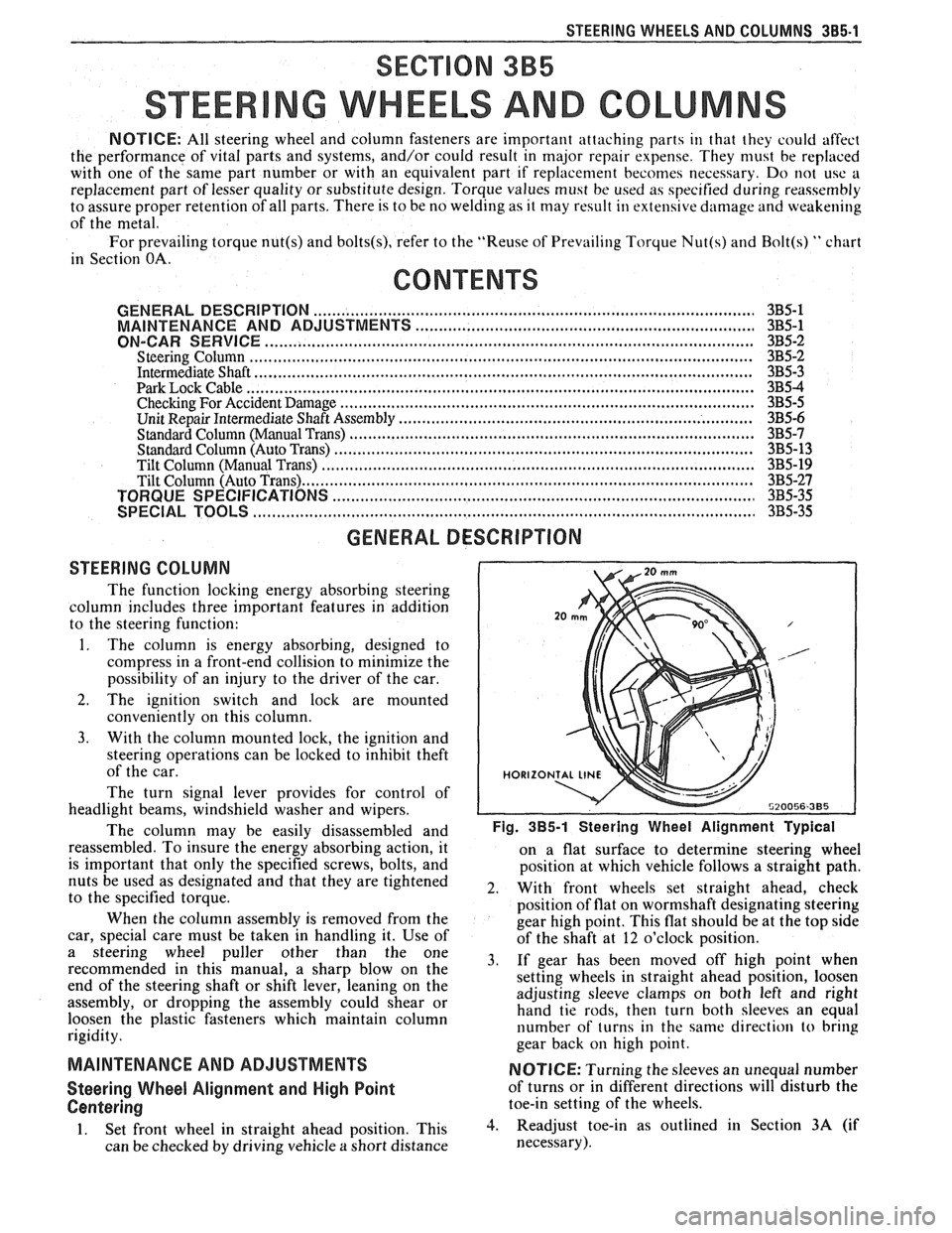
The column may be easily
disassembled and Fig. 385-1 Steering Wheel Alignment ~ypical
reassembled. To insure the energy absorbing action, it
on a flat surface to determine steering wheel
is important that only the specified screws, bolts, and
position at which vehicle follows a straight path.
nuts be used as designated and that they are tightened
2. With front wheels set straight ahead, check to the specified torque.
position of flat on wormshaft designating steering
When the column assembly is removed from the
gear high point. This flat should be at the top side
car, special care must be taken in handling it. Use of
of the shaft at 12 o'clock position.
a steering puller other than the One 3, if gear has been moved off high when recommended in this manual, a sharp blow on the
setting wheels in straight ahead position, loosen
end of the steering shaft or shift lever, leaning on the
assembly, or dropping the assembly could shear or adjusting
sleeve clamps on both left and right
hand tie rods, then turn both sleeves an equal
loosen the plastic fasteners which maintain column
rigidity. number
of turns in the same direction
to bring
gear back
on high point.
MAINTENANCE AND ADJUSTMENTS NOTICE: Turning the sleeves an unequal number
Steering Wheel Alignment and High Point of turns or in different directions will disturb the
Centering toe-in setting of the wheels.
1. Set front wheel in straight ahead position, This 3. Readjust toe-in as outlined in Section 3A (if
can be checked by driving vehicle
a short distance necessary).
Page 1177 of 1825
Ground Distribution
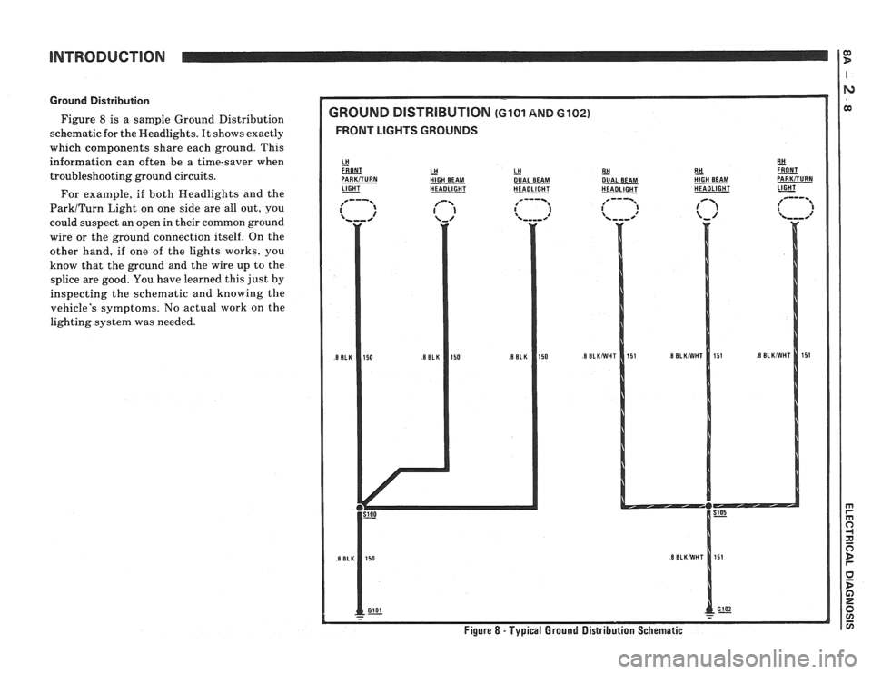
Figure 8 is a sample Ground Distribution
schematic for the Headlights. It shows exactly
which compcments share each ground. This
information can often be a time-saver when
troubleshooting ground circuits.
For example, if both Headlights and the
ParkITurn Light on one side are all out, you
could suspect an open in their common ground
wire or the ground connection itself. On the
other hand, if one of the lights works, you
know that the ground and the wire up to the
splice are good. You
have learned this just by
inspecting the schematic and knowing the
vehicle's symptoms. No actual work on the
lighting system was needed.
GROUND DlSTRlBUTlON (GI01 AND 6102)
FRONT LIGHTS GROUNDS
LH HlGH BEAM LH - DUAL
BEAM
LIGHT - HEADLIGHT HEADLIGHT RH
- DUAL
BEAM
HEADLIGHT E!! &T HIGH BEAM PARKiTURN HEAilLlGHT 1-
Figure 8 - Typical Ground Distribution Schematic
Page 1181 of 1825
TROUBLESHOOTING PROCEDURES
The following four-step troubleshooting pro-
cedure is recommended:
Step 1: Check the problem.
Perform a System Check to be sure you
understand what's wrong. Don't waste time
fixing part of the problem! Do not begin dis-
assembly or testing until you have narrowed
down the possible causes.
Step 2: Read the Electrical Schematic.
Study the schematic. Read the Circuit Oper-
ation text if you do not understand how the
circuit
should work. Check circuits that share
wiring with the problem circuit. The names of
circuits that share the same fuse, ground,
switch, etc., are included on each electrical
schematic. (Shared circuits are also shown on
Power Distribution, Ground Distribution,
Fuse Block Details, and Light Switch pages.)
Try to operate the shared circuits. If the
shared circuits work, then the shared wiring is
OK. The cause must be within the wiring used
only by the problem circuit. If several circuits
fail at the same time, chances are the power
(fuse) or ground circuit is faulty.
Step 3: Find the Cause and Repair.
* Narrow down the possible causes.
@ Use the Troubleshooting Hints.
@ Make the necessary measurements as
given in the System Diagnosis.
Step 4: Test the Repair
Repeat the System Check to be sure you
have fixed the whole problem.
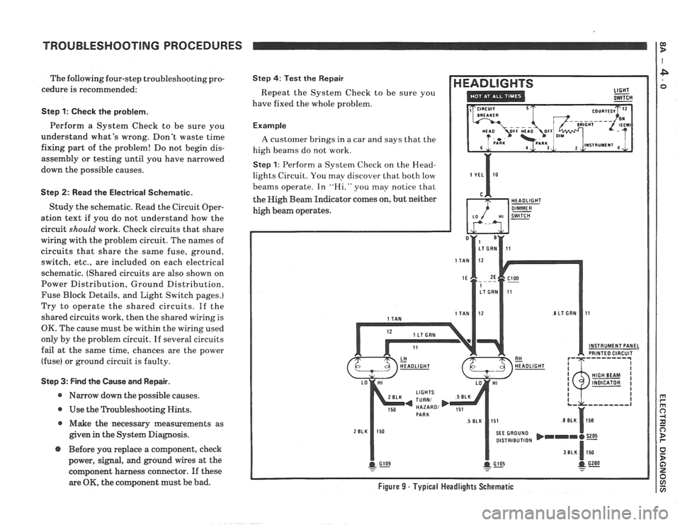
Example
A customer brings in a car and says that the
high beams do not work.
Step 1: Perform a System Check on the Head-
lights Circuit. You may discover that both low
beams operate. In
"Hi," you may notice that
the High Beam Indicator comes on, but neither
high beam operates.
INSTRUMENT PANEL PRINTED CIRCUIT
DISTRIBUTION
@ Before you replace a component, check
power, signal, and ground wires at the
component harness connector. If these
are
OK, the component must be bad. Figure 9 - Typical Headlights Schematic
Page 1182 of 1825
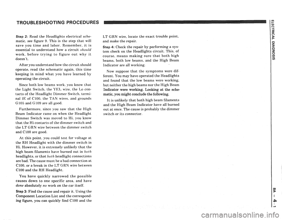
TROUBLESHOOTING PROCEDURES
Step 2: Read the Headlights electrical sche-
matic, see figure
9. This is the step that will
save you time and labor. Remember, it is
essential to understand how a circuit
should
work, before trying to figure out why it
doesn't.
After you understand how the circuit should
operate, read the schematic again, this time
keeping in mind what you have learned by
operating the circuit.
Since both low beams work. you know that
the
Light Switch. the YEI, wire. the I,o con-
tacts of the Headlight Dimmer Switch. termi-
nal
1E of C100. the TAN wires. and grounds
6105 and G 109 are all good.
Furthermore, since you saw that the High
Beam Indicator came on when the Headlight
Dimmer Switch was moved to Hi. you know
that the Hi contacts of the
dimmer switch and
the
I,T GRN wire between the dimmer switch
and ClOO are good.
At this point. you could test for
voltage at
the RH Headlight with the dimmer switch in
Hi. However. it is extremely unlikely that the
high beam filaments have burned out in
both
headlights. or that both headlight connections
are bad. The cause must be a bad connection at
C100, or a break in the I,T GRN wire between
ClOO and the RH Headlight.
I,T GRN wire, locate the exact trouble point,
and make the repair.
Step 4: Check the repair by performing a sys-
tem check on the Headlights circuit. This, of
course, means making sure that both high
beams, both low beams, and the High Beam
Indicator are all working.
Now suppose that the symptoms were dif-
ferent. You may have operated the Headlights
and found that the low beams were working,
but neither the high beams nor the High Beam
Indicator were working. Looking at the sche-
matic, you might conclude the
following.
It is unlikely that both high beam filaments
and the High Beam Indicator have all burned
out at once. The cause is probably the dimmer
switch or its connector.
You have quickly narrowed the possible
causes down to one specific area, and have
done absolutely
no work on the car itself.
Step 3: Find the cause and repair it. Using the
Component Location List and the correspond-
ing figure. you can quickly find ClOO and the
Page 1406 of 1825
INSTRUMENT PANEL: GAGES CLUSTER
I Oil Pressure Gage
(Continued from previous page)
indicates low
pressure
and oil
pressure is good
Coolant
Temperature Gage
does not indicate
HOT with Ignition
Switch in START or
BULB TEST, but
does operate
accurately
Do Test I: (Also see
Test A
terminal B)
Check DK GRN (35)
wire and Ignition
Switch for opens
Repairlreplace as
necessary
Oil Pressure Gage
indicates high
pressure at
all times
and oil pressure is
good Do
Test
J: (Also see
Test A terminal
8)
Oil Pressure Gage is
inaccurate Do
Test K: (also see
Test A terminal
8)
Do Test L
Tachometer does not
operate
Speedometer1
Odometer is
inaccurate Do
Test M
Do Test N: (with
5-33431-873 harness
connector available)
One or both
Odometers do not
operate properly,
but Speedometer
operates accurately
I
Check the
Instrument Cluster
Printed Circuit for
cracks or flaws
Replace the
Speedometer1
Odometer Assembly
(Continued in next column) (Continued from previous
column)
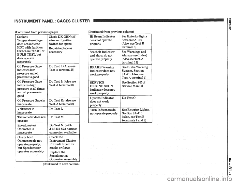
Hi Beam Indicator
does not operate
properly See
Exterior lights
Section 8A-110
(Also see Test
B
terminal 8)
I operate properly
I
(Also see Test A
I
Seatbelt Indicator
and alarm do not
BRAKE Warning Indicator does not
work properly
I
See Warnings and
Alarms (see Index)
SERVICE
ENGINE SOON
Indicator does not
does not work See
Brake Warning
System, Section
8A-41 (Also, see
Test A terminal
1)
See Section 6E of
1 Service Manual
Do Test O
r
(Also, see Test B
terminals 7 and
9)
Page 1462 of 1825
HEADLIGHTS WITH LAMP MONITOR
TROUBLESHOOTING HINTS
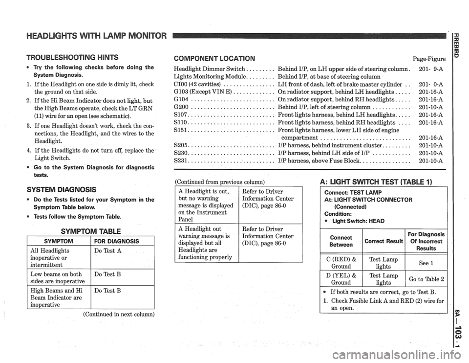
r Try the following checks before doing the
System Diagnosis.
1. If the Headlight on one side is dimly lit, check
the ground on that side.
2. If the Hi Beam Indicator does not light, but
the High Beams operate, check the LT GRN
(11) wire for an open (see schematic).
3. If one Headlight doesn't work, check the con-
nections, the Headlight, and the wires to the
Headlight.
4. If the Headlights do not turn off, replace the
Light Switch.
Go to the System Diagnosis for diagnostic
tests.
SYSTEM DIAGNOSIS
0 Do the Tests listed for your Symptom in the
Symptom Table below.
@ Tests follow the Symptom Table.
SYMPTOM TABLE
I SYMPTOM I FOR DIAGNOSIS I
All Headlights
inoperative or
intermittent Do
Test A
Beam Indicator are
(Continued in next column)
COMPONENT LOCATION Page-Figure
Headlight Dimmer Switch.
........ Behind IIP, on LH upper side of steering column. 201-
9-A
Lights Monitoring Module.
........ Behind IIP, at base of steering column
.. el00 (42 cavities) ................ LH front of dash, left of brake master cylinder
201- 0-A
.... 6103 (Except VIN E) ............. On radiator support, behind LH headlights.
201-16-A
.... 6104 .......................... On radiator support, behind RH headlights.
201-16-A
............ 6200 .......................... Behind IIP, left of steering column
201-10-A
.... S107. .......................... Front lights harness, behind LH headlights.
201-16-A
.... S110. .......................... Front lights harness, behind RH headlights
201-16-A
S151. .......................... Front lights harness, lower LH side of engine
compartment
............................ 201-16-A
........ S205. .......................... IIP harness, behind instrument cluster. 201-10-A
............ S230. .......................... IIP harness, behind LH side of IIP 201-10-A
............... S231. .......................... IIP harness, above Fuse Block. 201-10-A
(Continued from previous column)
A Headlight is out,
but no warning
message is displayed
on the Instrument
Panel
A: LIGHT SWITCH TEST (TABLE 1)
At: LIGHT SWITCH CONNECTOR
(Connected)
Condition: Light Switch: HEAD
Refer to Driver
Information Center
(DIC), page 86-0
A Headlight out
warning message is
displayed but all
Headlights are
functioning properly For Diagnosis
Connect
Correct Result Of Incorrect
1 Between 1 1 Results 1
Refer to Driver
Information Center
(DIG), page 86-0
I Ground (RED) I Te;ik,",mp I see 1 I
If both results are correct, go to Test B.
1. Check Fusible Link A and RED (2) wire for
an open.
D (YEL) &
Ground Test Lamp
lights Go to able