1988 PONTIAC FIERO fog light
[x] Cancel search: fog lightPage 1166 of 1825
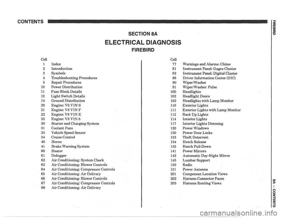
CONTENTS
ELECTRICAL DIAGNOSIS
Cell
1
2
3
4 5
10
11
12 14
20
21
22
23
30
31
33
34
40
4
1
60
61
62
63
64
65
66
67
68
Index
Introduction
Symbols
Troubleshooting Procedures Repair Procedures
Power Distribution
Fuse Block Details
Light Switch Details
Ground Distribution
Engine:
V6 VIN S
Engine: V8 VIN
F
Engine: V8 VIN E
Engine:
V8 VIN 8
Starter and Charging System
Coolant Fans
Vehicle Speed Sensor
Cruise Control Horns
Brake Warning System
Heater
Defogger
Air Conditioning: System Check
Air Conditioning: Blower Controls
Air Conditioning: Compressor Controls
Air Conditioning: Air Delivery
Air Conditioning: Blower Controls
Air Conditioning: Compressor Controls
Air Conditioning: Air Delivery Cell
77
8
1
82
86 90
9
1
100
102
103
110
111
112
114
117
120
130
133
134
135
141
143
145
150
151
201 202
203
Warnings and Alarms: Chime
Instrument Panel: Gages Cluster
Instrument Panel:
Digital Cluster
Driver Information Center
(DIC)
WiperlWasher
WiperlWasher: Pulse
Headlights
Headlight Doors
Headlights with Lamp Monitor
Exterior Lights
Exterior Lights with Lamp Monitor
Back Up Lights
Interior Lights
Interior Lights Dimming
Power Windows
Power Door Locks
Theft Deterrent
Hatch Release
Hatch Pull-Down
Power Mirrors
Automatic Day-Night Mirror
Lumbar Support
Radio Power Antenna
Component Location Views
Harness Connector Faces
Harness Routing Views
Page 1167 of 1825
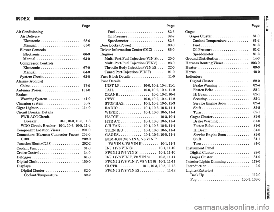
Page
Air Conditioning
Air Delivery
Electronic
.................... 68-0
Manual
....................... 65-0
Blower Controls
Electronic
.................... 66-0
Manual
....................... 63-0
Compressor Controls Electronic
.................... 67-0
Manual
....................... 64-0
................... System Check 62-0
Alarms (Audible)
Chime
......................... 77-0
Antenna(Power) ................... 151-0
Brakes
................. Warning System 41-0
................... Charging system 30-7
...................... Cigar Lighter 114-0
Circuit Breaker Details
PWR ACC Circuit
.......... Breaker 10.1.10.3.10.5.1 1.3
WDO Circuit Breaker
10.1. 10.3. 10.5. 11-4
.......... Component Location Views 201-0
Connectors (Harness Connector Faces) 202-0
el00 .......................... 202-0
............... Junction Block ((2238) 202-2
Coolant Fan
....................... 31-0
Cruise Control
..................... 34-0
Defogger
......................... 61-0
Digital Clock
...................... 150-0
Displays Digital Cluster
.................. 82-0
Coolant Temperature
........... 82-2
Page
......................... Fuel 82-3
................... Oil Pressure 82-2
.................. Speedometer 82-3
................. Door Locks (Power) 130-0
...... Driver Information Center (DIC) 86-0
Engines
... Multi-Port Fuel Injection (VIN S) 20-0
.... Multi-Port Fuel Injection (VIN 8) 23-0
.... Throttle
Body Injection (VIN E) 22-0
...... Tuned
Port Injection (VIN F) 21-0
................. Fuse Block Details 11-0
Fuse Details
........... INST LP 10.0.10.2.10.4.1 1.1
.............. TAIL 10.0.10.2.10.4.1 1.2
................ CRANK 10.0.10.2.1 0.4
.............. CTSY 10~0.10.2.10.4.1 1.2
......... STOP HAZ 10.1.10.3.10.5.1 1.3
............ RADIO 10.1.10.3.10.5.1 1.4
............ WIPER 10.1.10.3.10.5.1 1.4
.................... HATCH 10.2.1 0.4
........... HTR AlC 10.1.10.3.10.5.1 1.4
........... CIH.FAN 10.1.10.3.10.5.1 1.4
......... TURN BIU 10.1.10.3.10.5.1 1.4
............ GAGES 10.1.10.3.10.5.1 1.4
ECM-IGN
(V6 VIN S. V8 VIN F.
........ V8 VIN 8. V8 VIN E) 10.1.1 1.7
............ INJ 1 (V6 VIN S) 10.1.1 1.10
......... FPIINJ 2 (V6 VIN S) 10.1.1 1.10
... INJ 1 (V8 VIN F. V8 VIN 8) 10.3.1 1.11
FPIINJ 2 (V8 VIN F. V8 VIN 8) 10.3.1 1.11
............ CLSTR 10.1.10.3.10.5.1 1.13
............. FPIINJ 2 (V8 VIN E) 11-12
Page
Gages
................... Gages Cluster 81-0
........... Coolant Temperature 81-2
......................... Fuel 81-3
................... Oil Pressure 81-2
.................. Speedometer 81-3
................ Ground Distribution 14-0
Harness Routing Views
............. 203-0
........................... Heater 60-0
............................ Horns 40-0
Indicators
.................. Digital Cluster 82-0
................ Brake Warning 82-4
.................. Fasten Belts 82-1
...................... Hi Beam 82-1
...................... Security 82-1
............ Service Engine Soon 82-4
......................... Shift 82-5
......................... Turn 82-1
................... Gages Cluster 81-0
................ Brake Warning 81-0
.................. Fasten Belts 81-0
...................... Hi Beam 81-0
............ Service Engine Soon 81-0
......................... Shift 81-1
......................... Turn 81-0
Instrument Panel
Digital Cluster
.................. 82-0
Gages Cluster
................... 81-0
............ Interior Lights Dimming 117-0
...................... Introduction 2-0
Lights (Exterior)
........................ Back Up 112-0
...................... Fog 100.3,10 3.0
Page 1210 of 1825
BOWER DISTRIBUTION
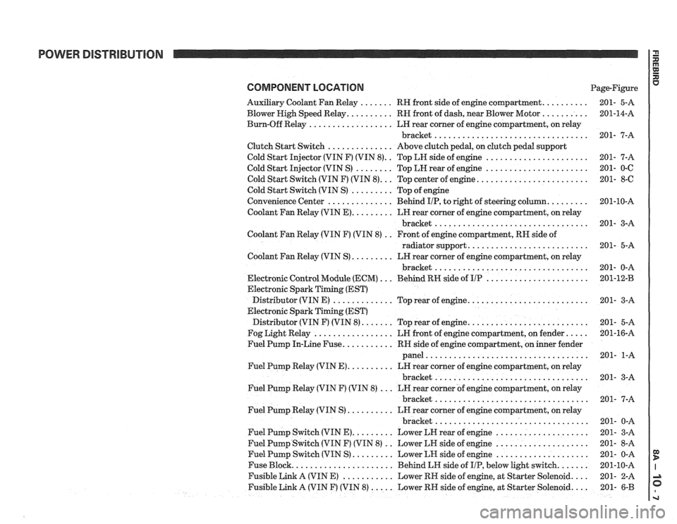
COMPONENT LOCATION Page-Figure
Auxiliary Coolant Fan Relay
. . . . . . . RH front side of engine compartment. . . . . . . . . .
Blower High Speed Relay. . . . . . . . . . RN front of dash, near Blower Motor . . . . . . . . . .
Burn-Off Relay . . . . . . . . . . . . . . . . . . LH rear corner of engine compartment, on relay
bracket
.................................
Clutch Start Switch . . . . . . . . . . . . . . Above clutch pedal, on clutch pedal support
Cold Start Injector (VIN F) (VIN
8). . Top LH side of engine . . . . . . . . . . . . . . . . . . . . . .
Cold Start Injector (VIN S) . . . . . . . . Top LH rear of engine . . . . . . . . . . . . . . . . . . . . . .
Cold Start Switch (VIN F) (VIN 8). . . Top center of engine. . . . . . . . . . . . . . . . . . . . . . . .
Cold Start Switch (VIN S) . . . . . . . . . Top of engine
Convenience Center
. . . . . . . . . . . . . . Behind IIP, to right of steering column. . . . . . . . .
Coolant Fan Relay (VIN E). . . . . . . . . LN rear corner of engine compartment, on relay
bracket
.................................
Coolant Fan Relay (VIN F) (VIN 8) . . Front of engine compartment, RH side of
radiator support.
. . . . . . . . . . . . . . . . . . . . . . . . .
Coolant Fan Relay (VIN S) . . . . . . . . . LH rear corner of engine compartment, on relay
bracket
.................................
Electronic Control Module (ECM) . . . Behind RN side of UP . . . . . . . . . . . . . . . . . . . . . .
Electronic Spark Timing (EST)
Distributor (VIN E)
. . . . . . . . . . . . . Top rear of engine. . . . . . . . . . . . . . . . . . . . . . . . . .
Electronic Spark Timing (EST)
Distributor (VIN F) (VIN
8). . . . . . . Top rear of engine. . . . . . . . . . . . . . . . . . . . . . . . . .
Fog Light Relay . . . . . . . . . . . . . . . . . LR front of engine compartment, on fender. . . . .
Fuel Pump In-Line Fuse. . . . . . . . . . . RR side of engine compartment, on inner fender
panel
...................................
Fuel Pump Relay (VIN E). . . . . . . . . . LN rear corner of engine compartment, on relay
bracket
.................................
Fuel Pump Relay (VIN F) (VIN 8) . . . LN rear corner of engine compartment, on relay
bracket
.................................
Fuel Pump Relay (VIN S) . . . . . . . . . . LH rear corner of engine compartment, on relay
bracket
.................................
Fuel Pump Switch (VIN E). . . . . . . . . Lower LN rear of engine . . . . . . . . . . . . . . . . . . . .
Fuel Pump Switch (VIN F) (VIN 8) . . Lower LN side of engine . . . . . . . . . . . . . . . . . . . .
Fuel Pump Switch (VIN S) . . . . . . . . . Lower LN side of engine . . . . . . . . . . . . . . . . . . . .
Fuse Block. . . . . . . . . . . . . . . . . . . . . . Behind LH side of IIP, below light switch. . . . . . .
Fusible Link A (VIN E) . . . . . . . . . . . Lower RN side of engine, at Starter Solenoid. . . .
Fusible Link A (VIN F) (VIN 8) . . . . . Lower RH side of engine, at Starter Solenoid. . . . 201- 6-B
Page 1213 of 1825
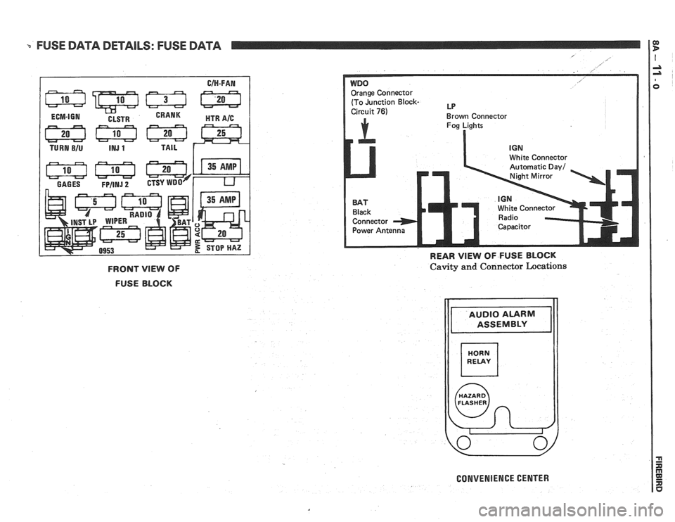
FUSE DATA DETAILS: FUSE DATA
E:ge Connector
(To Junction
Block- LP
Brown Connector
Fog Lights
I
ite Connector
White Connecto
REAR VlEW OF FUSE BLOCK
FRONT VlEW OF
FUSE BLOCK Cavity and Connector Locations
CONVENIENCE CENTER
Page 1342 of 1825
DEFOGGER
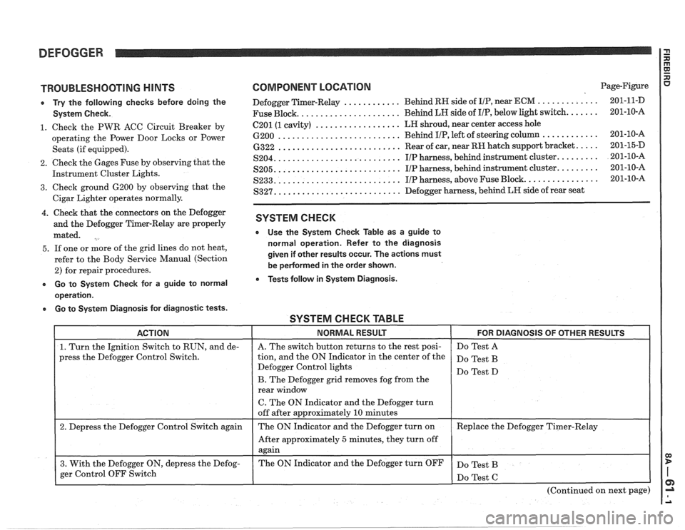
TROUBLESHOOTING HINTS
e Try the following checks before doing the
System Check.
1. Check the PWR ACC Circuit Breaker by
operating the Power Door Locks or Power
Seats (if equipped).
2. Check the Gages Fuse by observing that the
Instrument Cluster Lights.
3. Check ground 6200 by observing that the
Cigar Lighter operates normally.
4. Check that the connectors on the Defogger
and the Defogger Timer-Relay are properly
mated.
5. If one or more of the grid lines do not heat,
refer to the Body Service Manual (Section
2) for repair procedures.
e Go to System Check for a guide to normal
operation.
a Go to System Diagnosis for diagnostic tests.
COMPONENT LOCATION Page-Figure
............ ............. Defogger Timer-Relay Behind
RH side of IIP, near ECM 201-1 1-D
..................... Fuse Block. Behind LH side
of I/P, below light switch. ...... 201-10-A
.................. 6201 (1 cavity) LH
shroud, near center access hole
.......................... 6200 Behind IIP, left of steering column ............ 201-10-16
.......................... 6322 Rear of car, near RH hatch support bracket. .... 201-15-D
.......................... S204. IIP harness, behind instrument cluster. ........ 201-10-A
.......................... S205. IIP harness, behind instrument cluster. ........ 201-10-A
.......................... S233. IIP harness, above Fuse Block. ............... 201-10-A
.......................... S327. Defogger harness, behind LR side of rear seat
SYSTEM CHECK
e Use the System Check Table as a guide to
normal operation. Refer to the diagnosis
given if other results occur. The actions must
be
pedormed in the order shown.
Tests follow in System Diagnosis.
SYSTEM CHECK TABLE -- -
ACTION NORMAL RESULT FOR DIAGNOSIS OF OTHER RESULTS
1. Turn the Ignition Switch to RUN, and de-
press the Defogger Control Switch.
2. Depress the Defogger Control Switch again
3. With the Defogger ON, depress the Defog-
ger Control OFF Switch
I
A. The switch button returns to the rest posi-
tion, and the ON Indicator in the center of the
Defogger Control lights
B. The Defogger grid removes fog from the
rear window
C. The ON Indicator and the Defogger turn
off after approximately
10 minutes
The ON Indicator and the Defogger turn on
After approximately
5 minutes, they turn off
again
The ON Indicator and the Defogger turn OFF Do
Test A
Do Test B
Do Test D
Replace the Defogger Timer-Relay
Do Test B
(Continued on next page)
Page 1343 of 1825
DEFOGGER
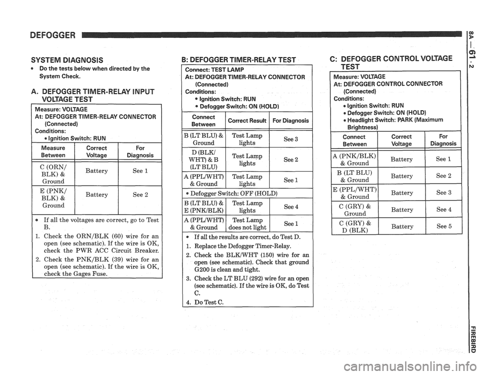
SYSTEM DIAGNOSIS
Do the tests below when directed by the
System Check.
A. DEFOGGER TIMER-RELAY INPUT
VOLTAGE TEST
At: DEFOGGER TIMER-RELAY CONNECTOR
(ORN/ I Battery
BLK) &
I Ground I
(PNK/ I Battery I See 2 BLK) & I
Ground
If all the voltages are correct, go to Test
B.
1. Check the ORN/BLK (60) wire for an
open (see schematic). If the wire is OK,
check the PWR ACC Circuit Breaker.
2. Check the PNK/BLK (39) wire for an
open (see schematic). If the wire is OK,
check the Gages Fuse.
-RELAY CONNECTOR
Ignition Svvitch: RUN
A (PPLIWWT) Test Lamp
& Ground does not light See 1
If all the
results are correct, do Test D.
1. Replace the Defogger Timer-Relay.
2. Check the
BLKIWKT (150) wire for an
open (see schematic). Check that ground
6200 is clean and tight.
3. Check the LT BLU (292) wire for an open
(see schematic).
If the wire is OK, do Test
6.
4. DoTest C.
B: DEFOGGER TIMER-RELAY TEST 6: DEFOGGER CONTROL VOLTAGE
TEST
At: DEFOGGER CONTROL CONNECTOR
e lgnition Switch: RUN
Defogger Switch: ON (HOLD)
a Headlight Switch: PARK (Maximum
I C (GRY) &
D (BLK) Battery
Page 1344 of 1825
DEFOGGER
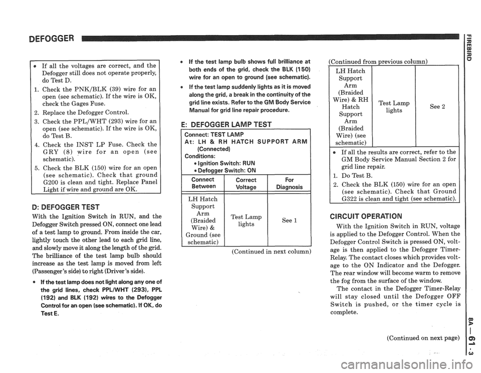
r If all the voltages are correct, and the
Defogger still does not operate properly,
do Test D.
1. Check the PNK/BLK (39) wire for an
open (see schematic). If the wire is OK,
check the Gages Fuse.
2. Replace the Defogger Control.
3. Check the PPL/WHT (293) wire for an
open (see schematic). If the wire is OK,
do Test B.
4. Check the INST LP Fuse. Check the
GRY
(8) wire for an open (see
schematic).
5. Check the BLK (150) wire for an open
(see schematic). Check that ground
6200 is clean and tight. Replace Panel
Light if wire and ground are OK.
D: DEFOGGER TEST
With the Ignition Switch in RUN, and the
Defogger Switch pressed
ON, connect one lead
of a test lamp to ground. From inside the car,
lightly touch the other lead to each grid line,
and slowly move it along the length of the grid.
The brilliance of the test lamp bulb should
increase as the test lamp is moved from left
(Passenger's side) to right (Driver's side).
0 If the test lamp does not light along any one of
the grid lines, check
PPLIWHT (2931, PPL
(192) and BLK (192) wires to the Defogger
Control for an open
(see schematic). If OK, do
Test
E.
If the test lamp bulb shows full brilliance at
both ends of the grid, check the BLK
(1 50)
wire for an open to ground (see schematic).
e If the test lamp suddenly lights as it is moved
along the grid, a break in the continuity of the
grid line exists. Refer to the
GM Body Service
Manual for grid line repair procedure.
E: DEFOGGER LAMP TEST
CH SUPPORT ARM
Ignition Switch: RUN
LH Hatch
Support Arm
(Braided Test
Lamp
lights See
1
Wire) &
Ground
(see
schematic)
(Continued in next column) (Continued
from previous column)
See 2
Arm
(Braided
Wire) (see
schematic)
I
If all the results are correct, refer to the
GM Body Service Manual Section 2 for
grid line repair.
1. Do Test B.
2. Check the BLK (150) wire for an open
(see schematic). Check that Ground
6322 is clean and tight (see schematic).
CIRCUIT OPERATION
With the Ignition Switch in RUN, voltage
is applied to the Defogger Control. When the
Defogger Control Switch is pressed ON, volt-
age is then applied to the Defogger
Timer-
Relay. The contact closes which provides volt-
age to the ON Indicator and the Defogger.
The rear window will become warm to remove
the fog from the surface of the window.
The contact in the Defogger Timer-Relay
will stay closed until the Defogger OFF
Switch is pushed, or the timer cycle is
complete.
(Continued on next page)
Page 1452 of 1825
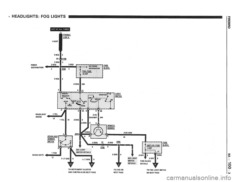
HEADLIGHTS: FOG LlGHTS
DISTRIBUTION
FUSE
- BLOCK -
TO INSTRUMENT CLUSTER
TO C103 ON AND ClOO PIN A2 ON NEXT PAGE
NEXT PAGE TO
FOG LIGHT SWITCH
ON NEXT PAGE