1988 PONTIAC FIERO clock setting
[x] Cancel search: clock settingPage 60 of 1825

AIR CONDITIONING 1B-17
If prescribed vacuum cannot be reached, close
vacuum control valve, shut off pump and look
for a leak at connections or pump.
3. When gauge reaches prescribed vacuum, the
system is fully evacuated. Close the high-side
gauge set valve and turn off the vacuum pump.
4. Watch low-side gauge to be sure vacuum holds
for five (5) minutes. If vacuum is held, discon-
nect vacuum hose at gauge set and then proceed
to charging.
5. If vacuum does not hold for five (5) minutes,
charge system with
420ml(1/2 pound) Refriger-
ant-12 and leak check. Discharge system again
and repair leak as necessary. Repeat evacuation
procedure.
To Begin Charging of the NC System
1. Start engine and set A/C mode control button on
"OFF. "
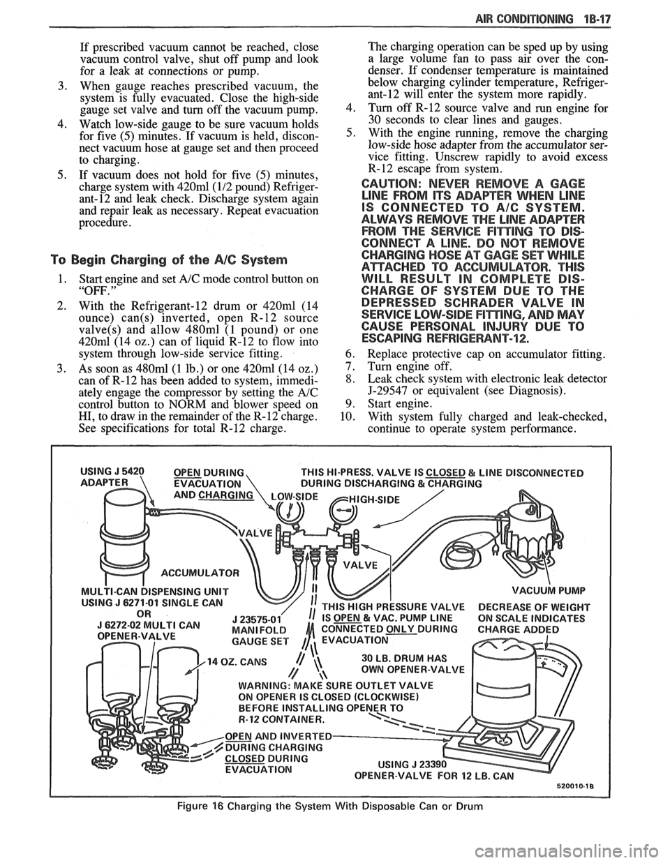
2. With the Refrigerant-12 drum or 420ml (14
ounce)
can(s) inverted, open R-12 source
valve(s) and allow 480ml (1 pound) or one
420m1 (14 02.) can of liquid R-12 to flow into
system through low-side service fitting.
3. As soon as 480ml (1 lb.) or one 420ml (14 oz.)
can of R-12 has been added to system, immedi-
ately engage the compressor by setting the
A/C
control button to NORM and blower speed on
HI, to draw in the remainder of the R-12 charge.
See specifications for total R-12 charge. The
charging operation can be sped up by using
a large volume fan to pass air over the con-
denser. If condenser temperature is maintained
below charging cylinder temperature,
Refriger-
ant-12 will enter the system more rapidly.
4. Turn off
R-12 source valve and run engine for
30 seconds to clear lines and gauges.
5. With the engine running, remove the charging
low-side hose adapter from the accumulator ser-
vice fitting. Unscrew rapidly to avoid excess
R-12 escape from system.
CAUTION: NEVER REMOVE A GAGE
LINE FROM ITS ADAPEER WHEN LINE
IS CONNECTED TO A/G SYSTEM.
ALWAYS REMOVE
THE LINE ADAPTER
FROM THE
SERVICE F1miNG TO DIS-
CONNECT A LINE. DO
NOT REMOVE
CHARGING
HOSE AT GAGE SET WHILE
ATTACHED TO ACGUMULBTOR. "THIS
WILL RESULT IN COMPLETE DIS-
CHARGE OF SYSTEM DUE TO THE
DEPRESSED SCHRADER VALVE IN
SERVICE LOW-SIDE
F17$TING, AND MAY
CAUSE PERSONAL
INJURY DUE TO
ESCAPING REFRIGERANT-72;.
6. Replace protective cap on accumulator fitting.
7. Turn engine off.
8. Leak check system with electronic leak detector
5-29547 or equivalent (see Diagnosis).
9. Start engine.
10. With system fully charged and leak-checked,
continue to operate system performance.
THIS HI-PRESS. VALVE IS
EVACUATION
ACCUMULATOR
ISPENSING UNIT
30 LB. DRUM HAS
OWN OPENER-VALVE
WARNING: MAKE SURE OUTLET VALVE
ON OPENER IS CLOSED (CLOCKWISE)
R-12 CQNTAINER.
OPEN AND INVERTED
DURING CHARGING
EVACUATION
Figure 16 Charging the System With Disposable Can or Drum
Page 152 of 1825

STEERING WHEELS AND COLUMNS 385.1
SECTION 3B5
STEER NG WHEELS AND COLUMNS
NOTICE: All steering wheel and column fasteners are important attaching parts in that they could affect
the performance of vital parts and systems, and/or could result in major repair expense. They
must be replaced
with one of the same part number or with an equivalent part if
replacement becomes necessary. Do not use a
replacement part of lesser quality or substitute design. 'Torque values must be used as specified during reassembly
to assure proper retention of all parts. There is to be no welding as
it may result in extensive damage and weakening
of the metal.
For prevailing torque
nut(s) and bolts(s), refer to the "Reuse of Prevailing Torque Nut(<) and Bolt(s) " chart
in Section OA.
CONTENTS
..................... ................................................................... GENERAL DESCRIPTION .. 3B5-1 ............................................. ........................ MAINTENANCE AND ADJUSTMENTS .. 3B5-1 ON-CAR SERVICE ........................................................................................................ 3B5-2
Steering Column ............................................................................................................ 3B5-2 ......................................................................................................... Intermediateshaft 3B5-3
Park Lock Cable .................................................................... 3B54 ......................................................................................... Checking For Accident Damage 3B5-5 ............................................................................ Unit Repair Intermediate Shaft Assembly 3B5-6
..................................................................................... Standard Column @lanual Trans) 3B5-7 ......................................................... ....................... Standard Column (Auto Trans) .. 3B5-13 Tilt Column (Manual Trans) ............................................................................................. 3B5-19
Tilt Column (Auto Trans). ................................................................................................ 3B5-27
................ .................... TORQUE SPECIFICATIONS .. .. 3B5-35
SPECIAL TOOLS .......................................................................................................... 3B5-35
GENERAL DESCRIPTION
STEERING COLUMN
The function locking energy absorbing steering
column includes three important features in addition
to the steering function:
1. 'The column is energy absorbing, designed to
compress in a front-end collision to minimize the
possibility of an injury to the driver of the car.
2. The ignition switch and lock are mounted
conveniently on this column.
3. With the column mounted lock, the ignition and
steering operations can be locked to inhibit theft
of the car.
The turn signal lever provides for control of
headlight beams, windshield washer and wipers.
The column may be easily
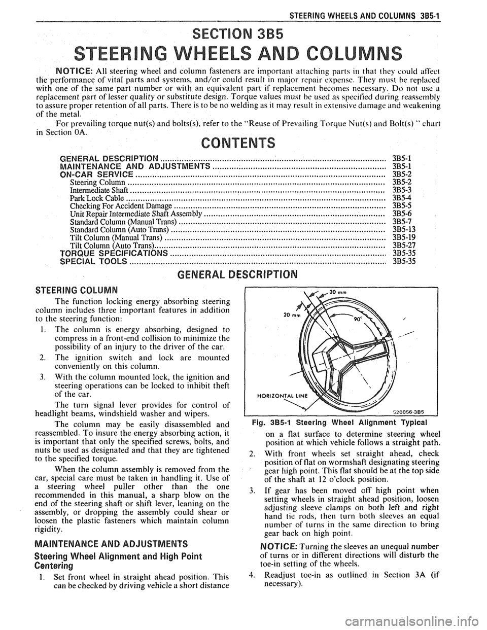
disassembled and Fig. 385-1 Steering Wheel Alignment ~ypical
reassembled. To insure the energy absorbing action, it
on a flat surface to determine steering wheel
is important that only the specified screws, bolts, and
position at which vehicle follows a straight path.
nuts be used as designated and that they are tightened
2. With front wheels set straight ahead, check to the specified torque.
position of flat on wormshaft designating steering
When the column assembly is removed from the
gear high point. This flat should be at the top side
car, special care must be taken in handling it. Use of
of the shaft at 12 o'clock position.
a steering puller other than the One 3, if gear has been moved off high when recommended in this manual, a sharp blow on the
setting wheels in straight ahead position, loosen
end of the steering shaft or shift lever, leaning on the
assembly, or dropping the assembly could shear or adjusting
sleeve clamps on both left and right
hand tie rods, then turn both sleeves an equal
loosen the plastic fasteners which maintain column
rigidity. number
of turns in the same direction
to bring
gear back
on high point.
MAINTENANCE AND ADJUSTMENTS NOTICE: Turning the sleeves an unequal number
Steering Wheel Alignment and High Point of turns or in different directions will disturb the
Centering toe-in setting of the wheels.
1. Set front wheel in straight ahead position, This 3. Readjust toe-in as outlined in Section 3A (if
can be checked by driving vehicle
a short distance necessary).
Page 287 of 1825

4B-14 REAR AXLE
plate to make sure that both pinion bearings
are properly seated.
1 - J-23597-11
2-- REAR PINION
3--- J-21777-43
4---- FRONT PINION
5- J-21777-42
6-HEX NUT
7 - J-23597-12
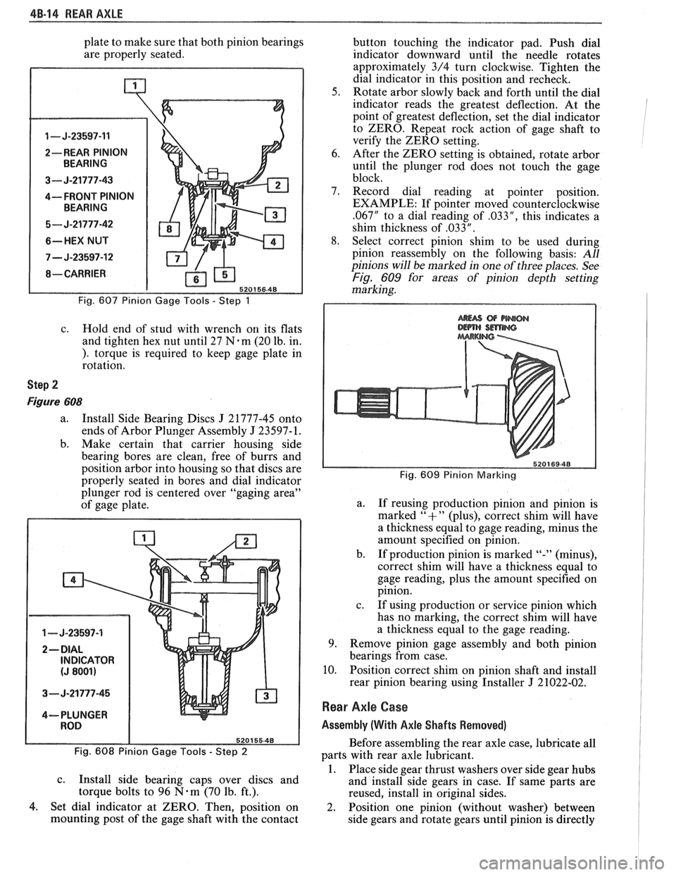
Fig. 607 Pinion Gage Tools - Step 1
c. Hold end of stud with wrench on its flats
and tighten hex nut until 27
N.m (20 lb. in.
). torque is required to keep gage plate in
rotation.
Step 2
Figure 608
a. Install Side Bearing Discs J 21777-45 onto
ends of Arbor Plunger Assembly
J 23597- 1.
b. Make certain that carrier housing side
bearing bores are clean, free of burrs and
position arbor into housing so that discs are
properly seated in bores and dial indicator
plunger rod is centered over "gaging area"
of gage plate.
1 - J-23597-4
3- J-21777-45
4--- PLUNGER
Fig. 608 Pinion Gage Tools
- Step 2
c.
Install side bearing caps over discs and
torque bolts to 96
N-m (70 lb. ft.).
4. Set dial indicator at ZERO. Then, position on
mounting post of the gage shaft with the contact button
touching the indicator pad. Push dial
indicator downward until the needle rotates
approximately 3/4 turn clockwise. Tighten the
dial indicator in this position and recheck.
5. Rotate arbor slowly back and forth until the dial
indicator reads the greatest deflection. At the
point of greatest deflection, set the dial indicator
to ZERO. Repeat rock action of gage shaft to
verify the ZERO setting.
6. After the ZERO setting is obtained, rotate arbor
until the plunger rod does not touch the gage
block.
7. Record dial reading at pointer position.
EXAMPLE: If pointer moved counterclockwise
.067" to a dial reading of .033", this indicates a
shim thickness of
,033 " .
8. Select correct pinion shim to be used during
pinion reassembly on the following basis:
All
pinions will be marked in one of three places. See
Fig. 609 for areas of pinion depth setting
marking.
Fig. 609 Pinion Marlcing
a.
If reusing production pinion and pinion is
marked
"+" (plus), correct shim will have
a thickness equal to gage reading, minus the
amount specified on pinion.
b. If production pinion is marked
"-" (minus),
correct shim will have
a thickness equal to
gage reading, plus the amount specified on
pinion.
c. If using production or service pinion which
has no marking, the correct shim will have
a thickness equal to the gage reading.
9. Remove pinion gage assembly and both pinion
bearings from case.
10. Position correct shim on pinion shaft and install
rear pinion bearing using Installer
J 21022-02.
Rear Axle Case
Assembly (With Axle Shafts Removed)
Before assembling the rear axle case, lubricate all
parts with rear axle lubricant.
1. Place side gear thrust washers over side gear hubs
and install side gears in case. If same parts are
reused, install in original sides.
2. Position one pinion (without washer) between
side gears and rotate gears until pinion is directly
Page 750 of 1825

DRIVEABILITY AND EMISSIONS 2.8L (VIN S) 6E3-CZ-15
NOTICE: Before instal ling new idle air control valve
assembly, the position of its pintle
MUST
be checked. If pintle is extended too far,
damage to the assembly may occur.
Measure
@ Distance from gasket mounting surface of IAC
valve assembly
(70) to tip of pintle, Dimension
"A" in Figure
C2-19.
Adjust
If distance is greater that 28 mm (1 118 in.), reduce -
it as follows:
a. If
IAC valve assembly has
a "collar" around
electrical connector end, use firm hand pressure
on pintle to retract it. (A slight side-to-side motion
may help.)
b. If IAC valve assembly has "no collar", compress
pintle-retaining spring toward body of the IAC
and try to turn pintle clockwise.
@ If pintle will turn, continue turning until
28mm
(1 118 in.) is reached. Return spring to
original position, with straight part of spring
end lined up with flat surface under the pintle
head.
@ If pintle will not turn, use firm hand pressure
to retract it.
Install or Connect
1. New IAC valve assembly gasket (71) on IAC valve
assembly
(70).
2. IAC valve assembly in idle airlvacuum signal
housing assembly
(60).
Tighten
IAC valve assembly to 18N.m (13 ft. Ibs.), with
wrench on hex surface only.
3. Electrical connector at IAC valve assembly (70).
Important
No physical adjustment is made to the IAC
assembly after installation.
IAC resetting occurs
after reinstallation on the vehicle, and is reset
after the engine is started and then the ignition
turned off.
IDLE AIR / VACUUM SIGNAL HOUSING
ASSEMBLY
(With
IAC Removed) (Figure C2-20)
Remove or Disconnect
1. Idle airlvacuurn signal assembly attaching screw
assemblies
(65) and (66).
2. Idle airlvacuum signal housing assembly (60).
3. Idle airlvacuum signal assembly gasket (67).
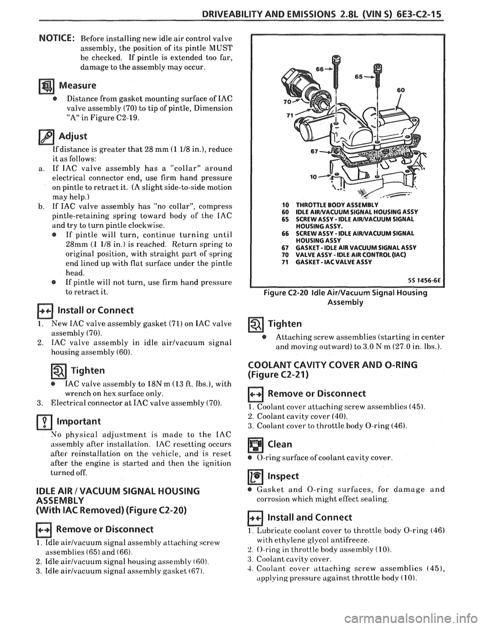
10 THROTTLE BODY ASSEMBLY
60 IDLE AIWVACUUM SIGNAL
HOUSING ASSY
65 SCREW ASSY - IDLE AIWVACUUM SIGNAL
HOUSING ASSY.
66 SCREW
ASSY
- IDLE AIWVACUUM SIGNAL
HOUSING ASSY
67 GASKET - IDLE AIR VACUUM SIGNAL ASSY 70 VALVE ASSY - IDLE AIR CONTROL (IAC) 71 GASKET - IAC VALVE ASSY
Figure C2-20 Idle AirIVacuum Signal Housing
Assembly
Tighten
@ Attaching screw assemblies (starting in center
and
moving outward) to 3.0 N.m (27.0 in. Ibs.).
COOLANT CAVITY COVER AND O-RING
(Figure
C2-21)
Remove or Disconnect
1. Coolant cover attaching. screw assemblies (45).
2. Coolant cavity cover (40).
3. Coolant cover to throttle body O-ring (46).
Inspect
@ Gasket and O-ring surfaces, for damage and
corrosion which might effect sealing.
Install and Connect
1. Lubricate coolant cover to throttle body O-ring (46)
with ethylene glycol antifreeze.
2. O-ring in throttle body assembly (10).
:3. Coolant cavity cover.
4. Coolant cover attaching screw assemblies (451,
applying pressure against throttle body (1 0).