1988 PONTIAC FIERO remote control
[x] Cancel search: remote controlPage 433 of 1825

6C-2 ENGINE FUEL
components such as the accelerator pumps and/or
air-fuel mixture leaning effects.
Various types and concentrations of alcohols are
used in commercial gasoline. Some alcohols are more
detrimental to fuel system components than others. If
an excessive amount of alcohol in the fuel is suspected
as the cause of a driveability condition, the following
procedure may be used to detect the presence of
alcohol in the fuel.
In this procedure, water is used to
extract the alcohol from the fuel. However, the specific
type of alcohol is not determined.
The fuel sample should be drawn from the
bottom part of the tank so that any water, if already
present, can be detected. The sample should be bright
and clear. If the sample appears cloudy or
contaminated with water as indicated by a water layer
in the bottom part of the sample, this procedure should
not be used. The fuel system should then be cleaned
(See Fuel System Cleaning).
Testing Procedure
1. Using a 100 ml cylinder with 1 ml graduation
marks, fill with fuel to the 90 ml mark.
2. Add 10 ml of water to bring the total fluid volume
to 100 ml and install a stopper.
3. Shake vigorously for 10 to 15 seconds.
4. Carefully loosen stopper to release pressure.
5. Close the stopper and shake vigorously again for
10 to 15 seconds.
6. Carefully loosen
stopper to release pressure.
7. Put the graduated cylinder on a level surface for
approximately 5 minutes to allow adequate liquid
separation.
If alcohol is present in the fuel, the volume of the
lower layer, which would now contain alcohol and
water will be greater than 10 ml. For example, if the
volume of the lower layer is increased to 15 ml, it
would indicate at least 5 percent alcohol in fuel. The
actual amount of alcohol may be somewhat greater
because this procedure does not extract all of the
alcohol from the fuel.
FUEL METERING
Throttle Body lnjection
(TBI)
With Throttle Body Injection (TBI), an injection
unit is placed on the intake manifold where the
carburetor is normally mounted. The TBI unit is
computer controlled and supplies the correct amount
of fuel during all engine operating conditions. See
Section 6E2 for information relative to operation and
diagnosis of TBI units.
Port Fuel lnjection
The ECM is in complete control of this fuel
delivery system during all driving conditions.
The intake manifold is used only to let air into the
engine. Fuel is injected by separate injectors that are
mounted over the intake valve.
With the Port Injection System, there is no need
for a Thermac, EFE, Map Sensor, Baro Sensor, A.I.R.
System, or Dual Bed Converter. This
system provides better cold driveability,
lower exhaust emissions and better throttle response.
In Sequential Fuel Injection systems (SFI),
injectors turn on at every crankshaft revolution. The
ECM controls the injector "on" time so that the
correct amount of fuel is metered, depending on
driving conditions.
Two interchangeable
"0" rings are used on the
injector that must be inspected when the injectors are
removed. Check
"0" rings for cuts or other type of
damage and replace as necessary.
The air cleaner is remotely mounted near the
radiator. It is connected to the intake manifold by air
intake ducting.
Also, mounted between the air cleaner and
intake, are the mass air flow sensor and throttle body.
Cold driveability characteristics are greatly
improved with the aid of an engine coolant supply to
the throttle body for rapid warm up.
The throttle body design uses an integral Idle Air
Control to govern idle speed and a Throttle Position
Sensor (TPS). The IAC and TPS are both controlled
by the ECM.
A large diameter fuel rail is attached to the intake
manifold and supplies fuel to all the injectors.
A fuel pressure tap is located on the rail for quick
pressure checks.
Fuel is recirculated through the rail continually
while the engine is running. This removes air and
vapors from the fuel as well as keeping the fuel cool
during hot weather operation.
A fuel pressure regulator is mounted on the fuel
rail. It maintains a constant 36 psi pressure across the
injectors under all operating conditions. It is
accomplished by controlling the amount of fuel that is
recirculated back to the fuel tank, based on engine
demand.
The pressure regulator also uses an
"0" ring for
attachment. The
"0" ring used is the same one that is
used for the injectors.
Some engines also have an accumulator that is
located in the fuel feed line near the cowl area. It is used
to dampen the vibration that is caused by the
pressurized fuel and the pulsing of the injector.
See Section 6E3 for more information and
diagnosis.
Fuel Feed and Return Pipe
When replacing fuel feed and return pipes, always
replace them with welded steel tubing meeting GM
Specification
124M, or its equivalent. The replacement
pipe must use the same type of fittings as the original
pipes to ensure the integrity of the connection.
NOTICE: Do not replace fuel pipe with fuel hose
or any other type of tubing such as copper or
aluminum. Only tubing meeting the 124M
specification is capable of meeting all the pressure
and vibration characteristics necessary to ensure
the durability standard required.
Always check and replace any
"0" rings or
washers that appear damaged.
Page 493 of 1825
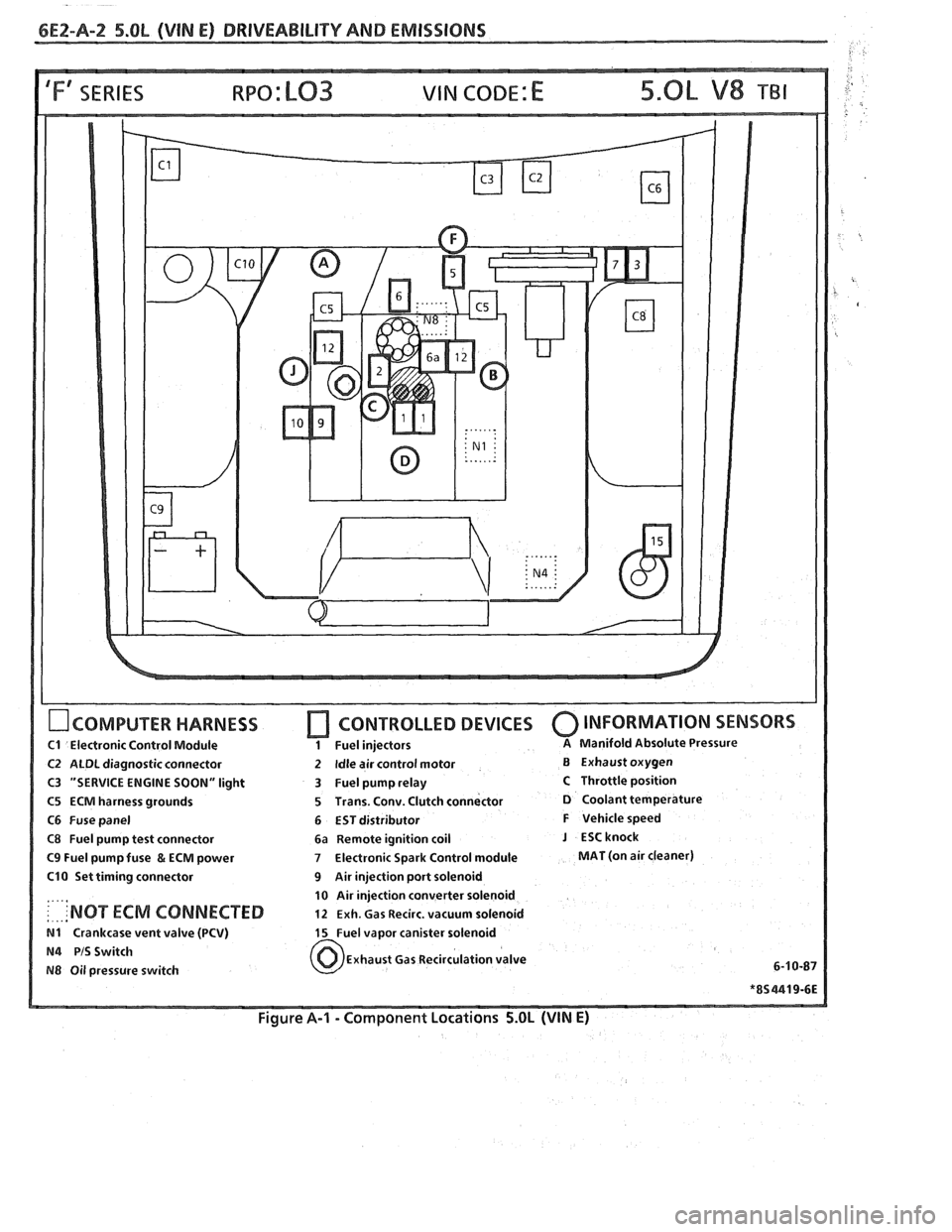
6E2-A-2 5.OL (VIN E) DRIVEABILIW AND EMISSIONS
IFf SERIES VIN CODE: E
OCOMPUTER HARNESS
C1 Electronic Control Module
C2 ALDL diagnostic connector
C3 "SERVICE ENGINE SOON" light
C5 ECM harness grounds
C6 Fuse panel
C8 Fuel pump test connector
C9 Fuel pump fuse & ECM power
C10 Set timing connector
....,
: . ... 'NOT ECM CONNECTED
N1 Crankcase vent valve (PCV)
N4 PIS Switch
N8 Oil pressure switch
[7 CONTROLLED DEVICES 0 INFORMATION SENSORS
1 Fuel injectors A Manifold Absolute Pressure
2 Idle air control motor B Exhaust oxygen
3 Fuel pump relay
C Throttle position
5 Trans. Conv. Clutch connector
D Coolant temperature
6 EST distributor
F Vehicle speed
6a Remote ignition coil
J ESCknock
7 Electronic Spark Control module MAT (on air cleaner)
9 Air injection port solenoid
10 Air injection converter solenoid
12 Exh. Gas Recirc. vacuum solenoid
15 Fuel vapor canister solenoid
Exhaust Gas Recirculation valve
6-1
0-87
Figure A-I - Component Locations 5.OL (VIN E)
Page 591 of 1825
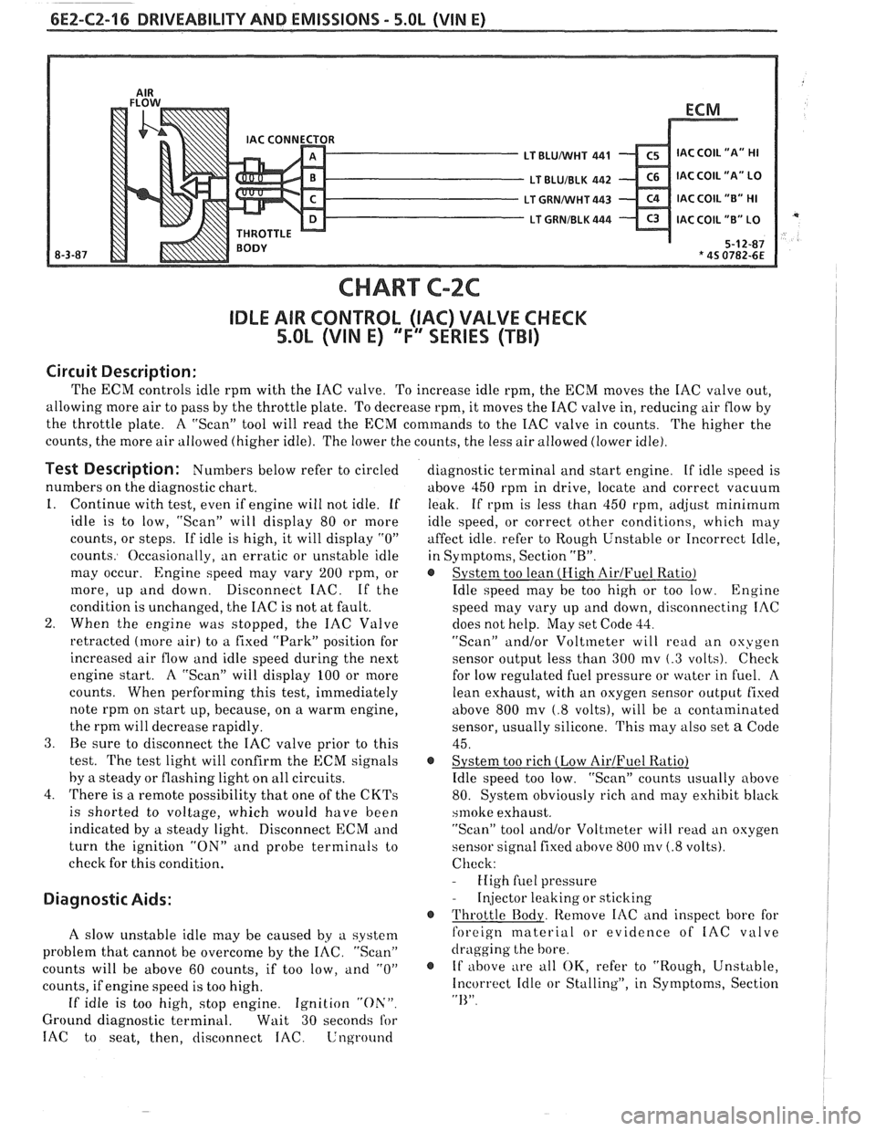
6E2-CZ-16 DRIVEABILITY AND EMISSIONS - 5.OL (WIN E)
CHART C-2C
IDLE AIR CONTROL (IAC) VALVE CHECK
5.OL (VIN E) "F'" SERIES (TBI)
Circuit Description:
The ECM controls idle rprn with the IAC valve. To increase idle rpm, the ECM moves the IAC valve out,
allowing more air to pass by the throttle plate. To decrease rpm, it moves the IAC valve in, reducing air flow by
the throttle plate. A "Scan" tool will read the
ECM commands to the IAC valve in counts.
The higher the
counts, the more air allowed (higher idle). The lower the counts, the less air allowed (lower idle).
Test Description: Numbers below refer to circled
numbers on the diagnostic chart.
1. Continue with test, even if engine will not idle. If
idle is to low, "Scan" will display 80 or more
counts, or steps. If idle is high, it will display
"0"
counts. Occasionally, an erratic or unstable idle
may occur.
Engine speed may vary 200 rpm, or
more, up and down. Disconnect IAC. If the
condition is unchanged, the IAC is not at fault.
2. When the engine was stopped, the IAC Valve
retracted (more air) to a fixed "Park" position for
increased air flow and idle speed during the next
engine start. A "Scan" will display 100 or more
counts. When performing this test, immediately
note rprn on start up, because, on a warm engine,
the rprn will decrease rapidly.
3. Be sure to disconnect the IAC valve prior to this
test.
The test light will confirm the ECM signals
by
a steady or flashing light on all circuits.
4. There is a remote possibility that one of the
CKTs
is shorted to voltage, which would have been
indicated by a steady light. Disconnect ECM and
turn the ignition
"ON" and probe terminals to
check for this condition.
Diagnostic Aids:
A slow unstable idle may be caused by a system
problem that cannot be overcome by the
IAC. "Scan"
counts will be above 60 counts, if too low,
and "0"
counts, if engine speed is too high.
If idle is too high, stop engine. Ignition "Oh'".
Ground diagnostic terminal. Wait 30 seconds for
IAC to seat, then, disconnect IAC. Lnground
diagnostic terminal and start engine. If idle speed is
above 450 rprn in drive, locate and correct vacuum
leak. If rpm is less than 450 rpm,
ad,jrlst minimum
idle speed, or correct other conditions, which may
affect idle. refer to Rough Unstable or Incorrect Idle,
in Symptoms, Section
"R".
@ System too lean (Hi.gh AirJFuel Ratio)
Idle speed may be too high or too low. Engine
speed may vary up and down, disconnecting IAC
does not help. May set Code
33.
"Scan" and/or Voltmeter will read an oxygen
sensor output less than 300 mv
(.3 volts). Check
for low regulated fuel pressure or water in
fuel. A
lean exhaust, with an oxygen sensor outpirt fixed
above 800
mv (.8 volts), will be a contaminated
sensor, usually silicone. This may also set
a Code
45.
@ System too rich (Low AirIFuel Ratio)
Idle speed too low. "Scan" counts usually above
80. System obviously rich and may exhibit black
srnoke exhaust.
"Scan" tool and/or Voltmeter will
read an oxygen
sensor signal fixed above 800
mv (.8 volts).
Check:
- High fuel pressure
- Injector leaking or sticking
@ Throttle Body. Remove IAC and inspect bore for
foreign material or evidence of
IAC valve
dragging the bore.
@ If above ;
e all OK, refer to "Rough, Unstable,
Incorrect Idle or Stalling", in Symptoms, Section
"I<".
Page 655 of 1825
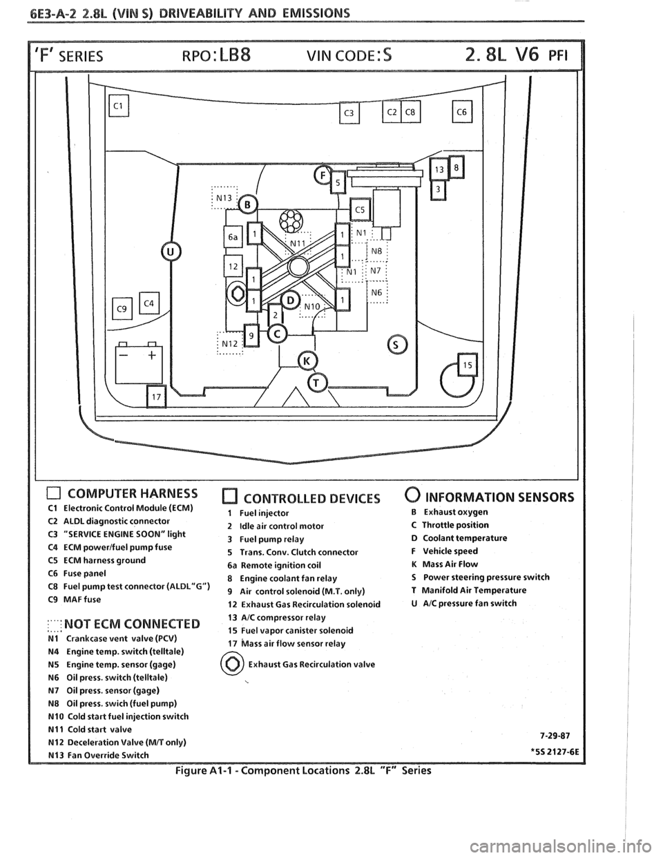
6E3-A-2 2.88, (VIM S) DRIVEABILITY AND EMISSIONS
'Fa SERIES
COMPUTER HARNESS
C1 Electronic Control Module (ECM)
C2 ALDL diagnostic connector
C3 "SERVICE ENGINE
SOON" light
C4 ECM powerlfuel pump fuse
C5 ECM harness ground
C6 Fuse panel
C8 Fuel pump test connector
(ALDL"G")
C9 MAFfuse
CONTROLLED DEVICES
1 Fuel injector
2
Idle air control motor
3 Fuel pump relay
5 Trans. Conv. Clutch connector
6a Remote ignition coil
8 Engine coolant fan relay
9 Air control solenoid (M.T. only)
12 Exhaust Gas Recirculation solenoid
0 INFORMATION SENSORS
B Exhaust oxygen
C Throttle position D Coolant temperature
F Vehicle speed
K Mass Air Flow
S Power steering pressure switch
T Manifold Air Temperature
U AIC pressure fan switch
13 AIC compressor relay
,..,a :'"' NOT ECM 'ONNECTED 15 Fuel vapor canister solenoid N1 Crankcase vent valve (PCV) 17 bass air flow sensor relay N4 Engine temp. switch (telltale)
N5 Engine temp. sensor (gage) Exhaust Gas Recirculation valve
N6 Oil press. switch (telltale)
N7 Oil press, sensor (gage)
N8 Oil press. swich (fuel pump)
N10 Cold start fuel injection switch
N11 Cold start valve 7-29-87 N12 Deceleration Valve (MIT only)
N13 Fan Override Switch *5S 2127-6E
Figure Al-l - Component Locations 2.8L "F" Series
Page 755 of 1825
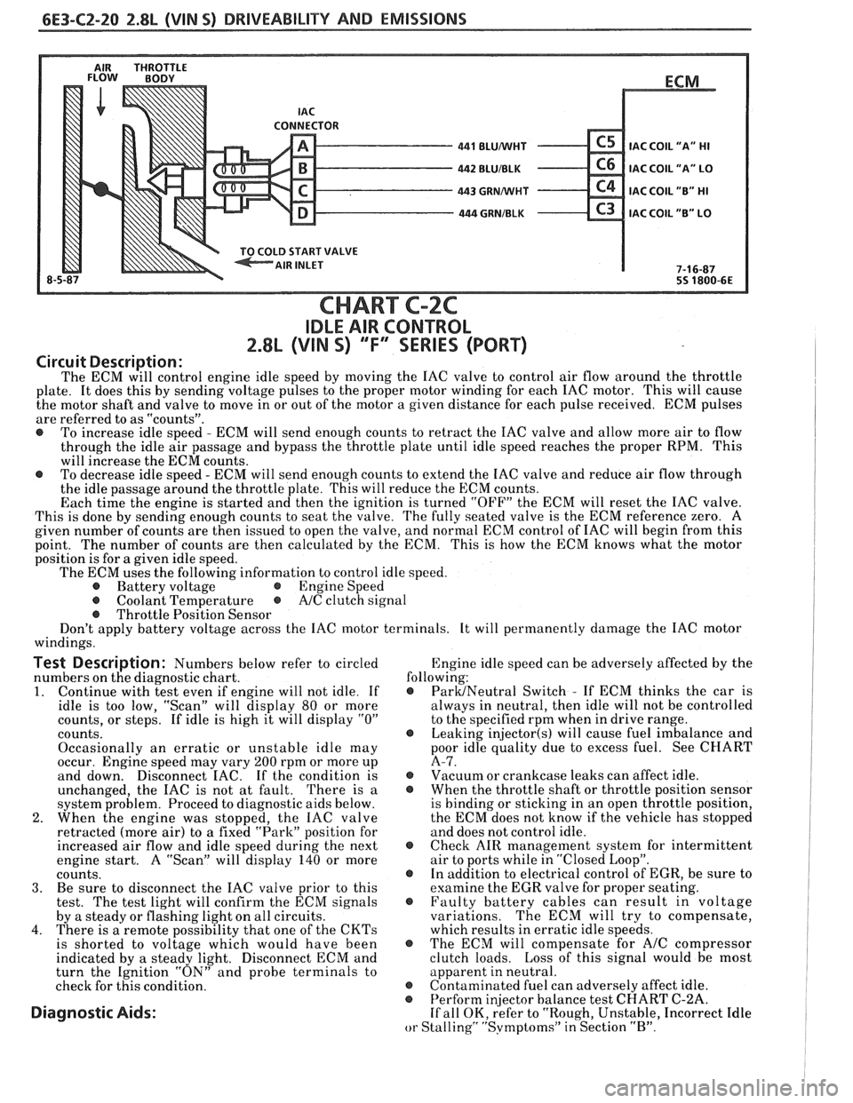
6E3-C2-20 2.8L (VIN S) DRIVEABILITY AND EMISSIONS
AIR THROTTLE FLOW BODY
LD START VALVE
8-5 BLUNVHT
BLUIBLK
GRMNVHT
. GRNIBLK
ECM
.
IAC COIL
"A" HI
IAC COIL "A" LO
IAC COIL "B" HI
C3 IAC COIL "B" LO
7-1 6-87
55 1800-6E
CHART C-2C
IDLE AIR CONTROL
2.8L (VIN S) ""F-SERIES (PORT)
Circuit Description:
The ECM will control engine idle speed by moving the IAC valve to control air flow around the throttle
plate. It does this by sending voltage pulses to the proper motor winding for each IAC motor. This will cause
the motor shaft and valve to move in or out of the motor a given distance for each pulse received. ECM pulses
are referred to as "counts".
@ To increase idle speed - ECM will send enough counts to retract the IAC valve and allow more air to flow
through the idle air passage and bypass the throttle plate until idle speed reaches the proper RPM. This
will increase the ECM counts.
@ To decrease idle speed - ECM will send enough counts to extend the IAC valve and reduce air flow through
the idle passage around the throttle plate. This will reduce the ECM counts.
Each time the engine is started and then the ignition is turned "OFF" the ECM will reset the IAC valve.
This is done by sending enough counts to seat the valve. The fully seated valve is the ECM reference zero. A
given number of counts are then issued to open the valve, and normal ECM control of IAC will begin from this
point. The
number of counts are then calculated by the ECM. This is how the ECM knows what the motor
position is for
a given idle speed.
The ECM uses the following information to control idle speed.
@ Battery voltage @ Engine Speed
@ Coolant Temperature @ A/C clutch signal
@ Throttle Position Sensor
Don't apply battery voltage across the IAC motor terminals. It will permanently damage the IAC motor
windings.
Test Description: Numbers below refer to circled Engine
idle speed can be adversely affected by the
numbers on the diagnostic chart. following:
1. Continue
with test even if engine will not idle. If @ ParUNeutral Switch - If ECM thinks the car is
idle is too low, "Scan" will display
80 or more always
in neutral, then idle will not be controlled
counts, or steps. If idle is high it will display
"0" to the specified rpm when in drive range.
counts.
@ Leaking injector(s) will cause fuel imbalance and
Occasionally an erratic or unstable idle may poor
idle quality due to excess fuel. See CHART
occur. Engine speed may vary
200 rpm or more up A-7.
and down. Disconnect
EAC. If the condition is @ Vacuum or crankcase leaks can affect idle.
unchanged, the IAC is not at fault. There is
a @ When the throttle shaft or throttle position sensor
system problem. Proceed to diagnostic aids below. is
binding or sticking in an open throttle position,
2. When the engine was stopped, the IAC valve the
ECM does not know if the vehicle has stopped
retracted (more air) to a fixed "Park" position for and does not control idle.
increased air flow and idle speed during the next
@ Check AIR management system for intermittent
engine start. A "Scan" will display
140 or more air
to ports while in "Closed Loop".
counts. @ In addition to electrical control of EGR, be sure to
3. Be sure to disconnect the IAC valve prior to this examine the
EGR valve for proper seating.
test. The test light will confirm the ECM signals @ Faulty battery cables can result in voltage
by a steady or flashing light on all circuits. variations. The
ECM will try to compensate,
4. There is a remote possibility that one of the CKTs which results in erratic idle speeds.
is shorted to voltage which would have been @ The ECM will compensate for A/C compressor
indicated by a steady light. Disconnect ECM and clutch
loads. Loss of this signal would be most
turn the Ignition "ON" and probe terminals to apparent
in neutral.
check for this condition.
@ Contaminated fuel can adversely affect idle. @ Perform in
or Stalling" "Svmptoms" in Section "B".
Page 764 of 1825
DRIVEABILITY AND EMISSIONS 2.8L (VIN S) 6E3-C4-1
SECTION C4
IGNI"F0N SYSTEM / EST
CONTENTS
GENERAL DESCRIPTION ................ C4-1 ON-CAR SERVICE ..................... C4-2
PURPOSE ......................... C4-1 SETTING TIMING.. .................. C4-2
OPERATION ....................... C4-1 HOW CODE 42 IS DETERMINED.. ....... C4-2
RESULTS OF INCORRECT OPERATION .... C4-2 PARTS INFORMATION ................. C4-2
DIAGNOSIS
......................... C4-2
CODEIZ.......................... C4-2
GENERAL DESCRIPTION
PURPOSE
The High Energy Ignition ([-IEI) system controls
fuel combustion by providing a spark to ignite the
compressed
airlfuel mixture at the correct time. To
provide improved engine performance, fuel economy,
and control of exhaust emissions, the
ECM controls
distributor spark advance (timing) with the Electronic
Spark Timing (EST) system.
Only the Electronic Spark Timing (EST) system
will be described here. Additional information on the
tIEI system is found in Section "6D".
To properly control ignition/combustion timing
the ECM needs to know:
@ Crankshaft position
@ Engine speed (rpm)
@ Mass Air Flow
@ Engine temperature
OPERATION
The EST system consists of the distributor
module, ECM, and connecting wires. The connector
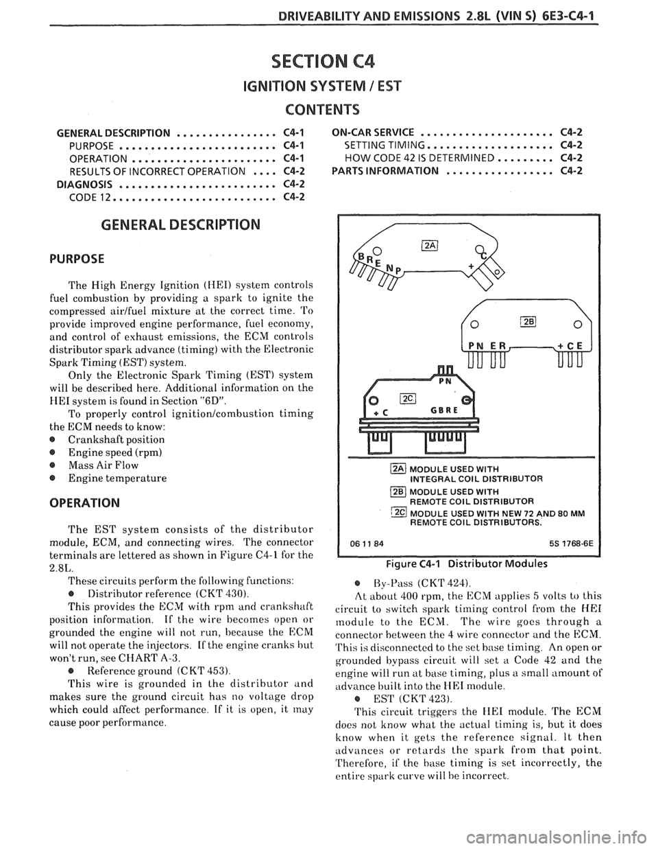
terminals are lettered as shown in Figure C4-1 for the
2.8L.
These circuits perform the following functions:
@ Distributor reference (CKT 430).
This provides the ECM with rpm ancl crankshaft
position information. If
the wire becomes open or
grounded the engine will not run, because the
ECM
will not operate the injectors. If the engine cranks hut
won't run, see CHART A-3.
@ Reference ground (C KT 453).
This wire is grounded in the distributor and
makes sure the ground circuit has no voltage drop
which could affect performance. If it is open, it
rnay
cause poor performance.
MODULE USED WITH INTEGRAL COlL DISTRIBUTOR
MODULE USED
WITH REMOTE COlL DISTRIBUTOR
MODULE USED
WITH NEW 72 AND 80 MM REMOTE COlL DISTRIBUTORS.
Figure C4-1 Distributor Modules
@ By-Pass (CKT 424).
At about 400 rpm, the ECM applies
5 volts to this
circuit to switch spark timing control from the
HE1
module to the ECM. The wire gocs through a
connector between the
4 wire connector and the ECM.
This is disconnectcd to the set base timing. An open or
grounded bypass circuit will set
a Code 42 and the
engine will run at hase timing, plus a small amount of
advance built into the
HE1 n~odule.
@ EST (CKT423).
This circuit triggers the FIE1 module. The ECM
does not know what the actual timing is, but it does
know when it gets the reference signal. It then
udva~ces or retards the spark from that point.
Therefore, if the
hase timing is set incorrectly, the
entire spark curve will be incorrect.
Page 907 of 1825
6E3-C2-20 5.0L (VIN F) & 5.7L (WIN 8) DRIVEABILITY AND EMISSIONS
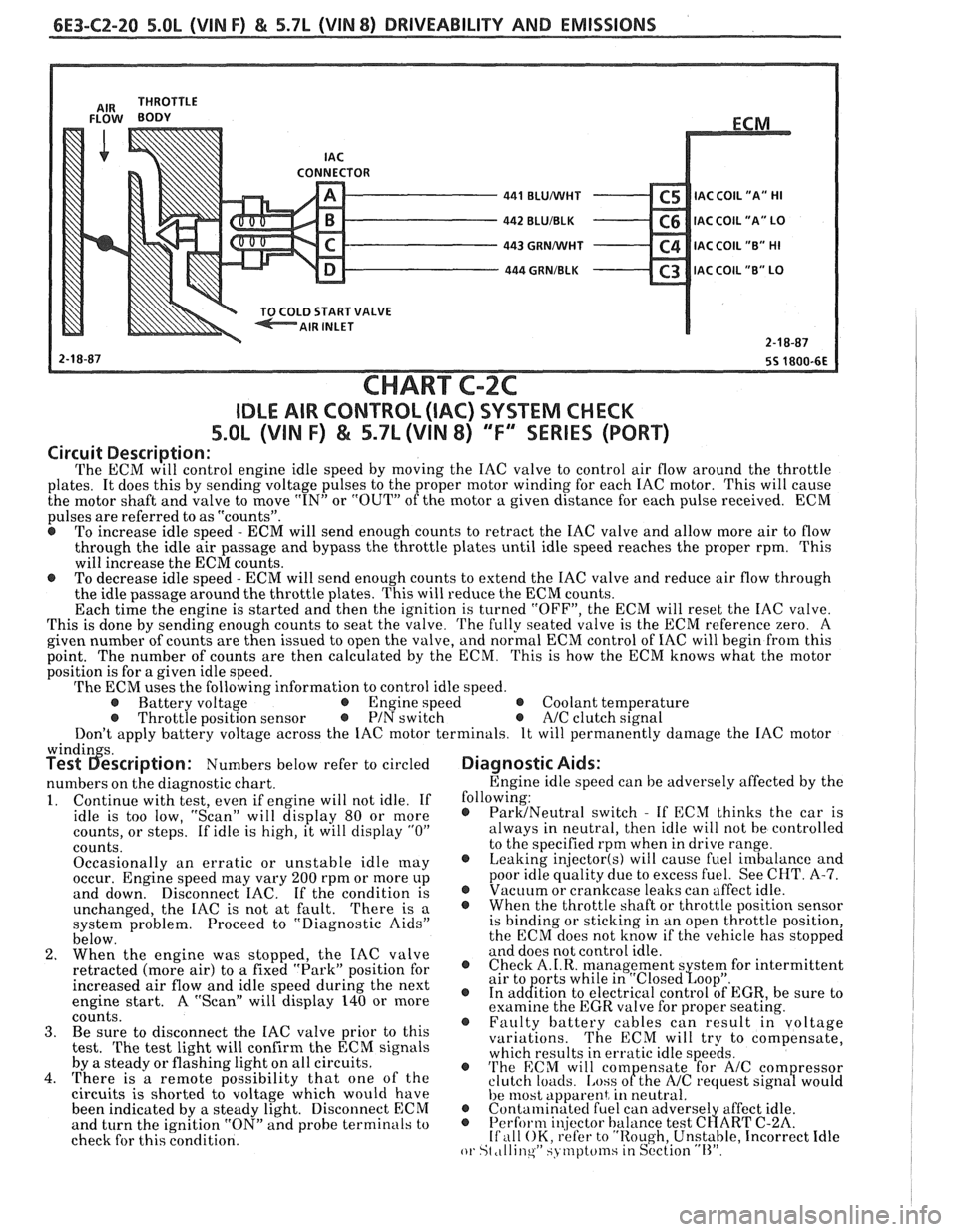
CONNECTOR - 441 BLUMlHT C5 IAC C0lL1'A" HI - 442 BLUIBLK C6 IAC COIL "A" LO - 443 GRNMlHT C4 IAC COIL "B" HI - 444 GRNIBLK C3 lAC COIL "B" LO v
START VALVE
CHART C-2C
IDLE AIR CONTROL (IAC) SYSTEM CHECK
S.OL (VIN F) & 5.7L (VIN 8) "F'" SERIES (PORT)
Circuit Description:
The ECM will control engine idle speed by moving the IAC valve to control air flow around the throttle
plates. It does this by sending voltage pulses to the proper motor winding for each IAC motor. This will cause
the motor shaft and valve to move
"IN" or "OUT" of the motor a given distance for each pulse received. ECM
pulses are referred to as "counts".
@ To increase idle speed - ECM will send enough counts to retract the IAC valve and allow more air to flow
through the idle air passage and bypass the throttle plates until idle speed reaches the proper rpm. This
will increase the ECM counts.
e To decrease idle speed - ECM will send enough counts to extend the IAC valve and reduce air flow through
the idle passage around the throttle plates. This will reduce the ECM counts.
Each time the engine is started and then the ignition is turned "OFF", the ECM will reset the IAC valve.
This is done by sending enough counts to seat the valve.
The fully seated valve is the ECM reference zero. A
given number of counts are then issued to open the valve, and normal ECM control of IAC will begin from this
point. The
number of counts are then calculated by the ECM. This is how the ECM knows what the motor
position is for a given idle speed.
The ECM uses the following information to control idle speed.
@ Battery voltage @ Engine speed @ Coolant temperature @ Throttle position sensor @ PIN switch e A/C clutch signal
Don't apply battery voltage across the IAC motor terminals. It will permanently damage the IAC motor
windin s. Test 6escription: Numbers below refer to circled
numbers on the diagnostic chart.
1. Continue with test, even if engine will not idle. If
idle is too low, "Scan" will display 80 or more
counts, or steps. If idle is high, it will display
"0"
counts.
Occasionally an erratic or unstable idle
[nay occur. Engine speed may vary 200 rpm or more up
and down. Disconnect IAC. If the condition is
unchanged, the IAC is not at fault.
There is a
system problem. Proceed to "Diagnostic Aids"
below.
2. When the engine was stopped, the IAC valve
retracted (more air) to
a fixed "Park" position for
increased air flow and idle speed during the next
engine start. A "Scan" will display 140 or more
coiints. 3. Be sure to disconnect the IAC valve prior to this
test.
The test light will confirm the ECM signals
by a steady or flashing light on all circuits.
4. There is a remote possibility that one of the
circuits is shorted to voltage which would have
been indicated by a steady light. Disconnect ECM
and turn the ignition "ON" and probe terminals to
check for this condition.
Diagnostic Aids:
Engine idle speed can be adversely affected by the
following:
@ ParMNeutral switch - If ECM thinks the car is
always in neutral, then idle will not be controlled
to the specified rpm when in drive range.
@ Leaking injector(s) will cause fuel imbalance and
poor idle quality due to excess fuel. See CHT.
A-7. @ Vacuum or crankcase leaks can affect idle. @ Whenthethrottleshaftorthrottlepositionsensor
is binding or sticking in an open throttle position,
the ECM does not know if the vehicle has stopped
and does not control idle.
@ Check A.I.R. management s stem for intermittent
air to orts while in "~losed~oo~". @ In ad&tion to electrical control of EGR, be sure to
examine the EGR valve for proper seating.
@ Faulty battery cables can result in voltage
variations. The ECM will try to compensate,
which results in erratic idle speeds.
@ 'I'he ECM will com ensate for A/C com ressor
clutch loacls. [.ass ofthe NC request sign8 would
he 11lost apparent, in neutral. @ Contalninatecl fuel can adverse1 affect idle. @ Perform i~!jector balance test C~ART C-2A. If ,111 OK, refer to "Rough, Unstable, Incorrect Idle or St ,tllinqW SJ tnptcfinsiin S~'ction "11''.
Page 1500 of 1825
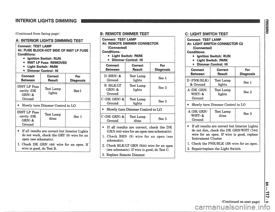
INTERIOR LIGHTS DIMMING
(Continued from facing page) B: REMOTE DIMMER TEST
Between I Result I Diagnosis
A: INTERIOR LlGHTS DIMMING TEST
Connect: TEST LAMP
At: FUSE BLOCK-HOT
SIDE OF lNST LP FUSE
Conditions:
@ ignition Switch: RUN
@ INST LP Fuse: REMOVED
r Light Switch: PARK
@ Dimmer Control: HI
cavity (DK
GRN)
& lights
Ground
Connect I Correct
@ Slowly turn Dimmer Control to LO
For
Ground
INST LP Fuse
cavity (DK
GRN)
&
r If all results are correct but Interior Lights
do not work, check the GRY
(8) wire for an
I open (see schematic). I
Test Lamp
dims
1. Check DK GRN (44) wire for an open. If
wire is good, do Test
B.
See 1
CONNECTOR
@ Light Switch: PARK
1. Check BRN (9) wire for an open (see
re is good, do Test C.
6: LlGHT SWITCH TEST
Connect: TEST LAMP
At:
LIGHT SWITCH CONNECTOR 62
(Connected)
Conditions:
@ Ignition Switch: RUN
@ Light Switch: PARK
r Dirnmer Control: HI
Connect
Between
D (PNWBLK)
& Ground
@ Slowly turn Dimmer Control to LO
Correct
Result
A (DK GRNI
WHT) &
Ground
I A (DK GRNI I Test Lamp / See 1
WHT) & dims
For
Diagnosis
Test Lamp
lights
I Ground I I I
See 1
Test Lamp
lights
If all results are correct but Interior Lights
do not dim, check the DK
GRNIWNT (744)
wire for an open. If wire is good, replace
Instrument Cluster.
1. Check the PNKIBLK (39) wire for an open.
See
2
1 2. Repairlreplace
the Light Switch. I
(Continued on next page)