1988 PONTIAC FIERO checking oil
[x] Cancel search: checking oilPage 22 of 1825
MAINTENANCE AND LUBRICATION OB-5
Throttle linkage inspection -- Inspect for inter-
ference, binding, damaged or missing parts.
Engine drive belts inspection - Inspect all
belts for cracks, fraying and wear. Adjust or replace as
needed.
Rear axle service (if equipped) - Check gear
lubricant level and add if needed. For cars equipped with a
limited slip rear axle, fluid does not require changing
(except Caprice and Corvette
- change fluid and required
additive at first
7,500 miles (12 500 km). See your
Owner's Manual or "Recommended Fluids
& Lubricants
Chart" in this section.
IF YOU USE YOUR GAR TO PULL A TRAILER,
CHANGE GEAR LUBRICANT EVERY 7,500 MILES
(12 500 KM).
NOTICE: A large loss in this system may indicate a
problem. Have it inspected and repaired at once.
Power antenna - Clean and then lubricate power
antenna mast. The proper lubricant as shown in Figure
OB-2 should be used.
AT LEAST ONCE A YEAR
Lap and shoulder belts condition and opera-
tion
- Inspect belt system, including webbing, buckles,
latch plates, retractors, guide loops and anchors.
Moveable head restraint operation - On cars
with moveable restraints, make sure restraints stay in the
desired position. (See adjustment instructions in your
Owner's Manual.)
Seatback latch and recliner operation on
cars equipped
with recliner seat --- Be sure seat-
backs latch on those cars with folding seats using mechan-
ical latches. Make sure the recliner is holding by pushing
and pulling on the top of the
seatback while it is reclined.
See your Owner's Manual for seat operating information.
Spare tire and jack storage- Be alert to rattles
in rear of car. Make sure the space tire, all jacking equip-
ment, any tire inflator and any covers or doors are securely
stowed at all times. Oil jack ratchet or screw mechanism
after each use.
Key lock service - Lubricate key lock cylinder at
least annually.
Body lubrication service - Lubricate all body
door hinges including the tailgate or hatchback lid (if
equipped). Also lubricate the body hood, fuel door and
rear compartment hinges and latches including interior
glove box and counsel doors, and any folding seat
hardware.
"Fansmissionltransaxle neutral or clutch
starl switch operation
CAUnON: Before pedorming the follow-
ing safety switch check, be sure to have
enough room around the car. Then, firmly
apply both the parking brake (see your
Owner's Manual for procedure) and the
regular brakes. Do not use the accelerator pedal.
If the engine
starls, be ready to turn
off the ignition promptly. Take these pre-
cautions because the car could move
without warning and possibly cause per-
sonal injury or properly damage. On auto-
matic transmissionltransaxle cars, try to
starl the engine in each gear. The starler
should crank only in "Park" or "Neutral."
On manual transmissionltransaxle cars,
place the
shiR lever in "Neutral," push the
clutch halfway and try to starl. The starler
should crank only when the clutch is fully
depressed.
Steering column lock operation
- While
parked, try to turn key to "Lock" in each gear range. The
key should turn to "Lock" only when gear is in "Park" on
automatic or "Reverse" on manual
transmissionltransax-
le. On cars with key release lever, try to turn key toULock"
without depressing the lever. The key should turn to
"Lock" only with the key lever depressed. On all vehicles,
the key should come out only in "Lock."
Parking brake and transmissionltransaxle
"Park" mechanism operation
CAUT1ON:Before checking the holding
ability of the parking brake and automatic
transmissionltransaxle "Park" mecha-
nism, park on a fairly steep hill with
enough room for movement in the down-
hill direction. To reduce the risk of person-
al injury or property damage, be prepared
to apply the regular brakes promptly if the
car begins to move.
To check the parking brake, with the engine running and
transmission/transaxle in "Neutral." slowly remove foot
pressure from the regular brake pedal (until the car is held
by only the parking brake).
To check the automatic transmissionltransaxle "Park"
mechanism holding ability, release all brakes after shift-
ing the transmissionltransaxle to "Park."
ljnderbody flushing - At least every spring,
tlush from the underbody with plain water any corrosive
materials used for ice and snow removal and dust control.
Take care to thoroughly clean any areas where mud and
other debris can collect.
Sediment packed in closed areas
of the vehicle should be loosened before being flushed.
Engine cooling system service - Inspect
coolant and freeze protection. If dirty or rusty, drain, flush
and refill with new coolant. Keep coolant
at the proper
mixture as specified in your Owner's Manual. This pro-
vides proper freeze protection. corrosion inhibitor level
and engine operating temperature. Inspect hoses and re-
place if cracked. swollen or deteriorated. Tighten hose
clamps. Clean outside of radiator and air conditioning
condensor. Wash radiator filler cap and neck.
To help
ensure proper operation. a pressure test of both the cooling
system and cap is also recommended. (See maintenance
schedule charts in Figure
OB-l for the recommended
coolant change interval.)
Page 98 of 1825
R-4 818 CONDITIONING COMPRESSOR OVERHAUL 1D1-19
retainers are to be removed, remove two sets and
then rotate compressor and Holding Fixture
J-25008-A in vise for access to the remaining two
valve plates and retainers.
Install or Connect
1. Install Discharge Valve Plates and/or Retainers.
Reposition compressor and Holding Fixture in
vise as necessary for access.
Valve plates must
be tight
following retainer assembly.
2. Reinstall compressor Shell as described in
SHELL AND O-RINGS replacement
procedures.
3. Evacuate and charge the refrigerant system
according to the directions in Section
1B.
CYLINDER AND SHAFT ASSSEMBLY
Remove or Disconnect
Discharge the refrigerant system according to the
directions in Section
1B.
Remove the Clutch Plate and Hub assembly as
described in CLUTCH PLATE AND HUB
removal procedure.
Perform Steps
1 through 4 of CLUTCH ROTOR
AND BEARING removal procedure but do not
loosen or remove the pulley rim mounting screws.
Remove the Clutch Rotor and Bearing, Clutch
Coil and Pulley Rim as an assembly. Be careful
not to drop the Puller Guide J-25031, when
removing the assembly.
Remove the shaft seal as described in SHAFT
SEAL removal procedure.
Remove the front head as described in FRONT
HEAD REMOVAL procedure.
Remove the thrust and belleville washers as
described in THRUST AND BELLEVILLE
WASHERS removal procedures.
Remove the compressor shell as described in
SHELL removal procedure.
Remove the discharge valve plate and retainer as
described in DISCHARGE VALVE PLATE
AND RETAINER removal procedure.
Remove the high pressure relief valve as
described in
HIGH PRESSURE RELIEF
VALVE REMOVAL PROCEDURE.
L
Install or Connect
1. Replace above parts in opposite order.
2. Evacuate and charge the refrigerant system
according to the directions in Section
1B.
LEAK TESVING (EXTERNAL AND INTERNAL)
Bench-Check Procedure
1. Install Test Plate J-9625-A on Rear Head of
compressor.
2. Attach center hose of Manifold Gage Set on
Charging Station to a refrigerant drum standing
in an upright position and open valve on drum.
3. Connect Charging Station high and low pressure
lines to corresponding fittings on Test Plate J-9625-A, using
5-5420 Gage
Adapters if hoses
are not equipped with valve depressors.
Suction port (low-side) of compressor has
large internal opening. Discharge port
(hi-side) has smaller internal opening into
compressor.
Open low-pressure control, high-pressure control
and refrigerant control on Charging Station to
allow refrigerant vapor to flow into compressor.
Using a Leak Detector, check for leaks at
Pressure Relief Valve, compressor shell to
cylinder, compressor front head seal, and
compressor Shaft Seal. After checking, shut off
low pressure control and high pressure control on
Charging Station.
If an external leak is present, perform the
necessary corrective measures and recheck for
leaks to make certain the leak has been corrected.
Loosen the Manifold Gage hose connections to
the Gage Adapters J-5420 connected to the low
and high sides and allow the vapor pressure to
release from the compressor.
Disconnect both Gage Adapters
5-5420 from the
Test Plate J-9625-A.
Rotate the complete compressor assembly (not
the crankshaft or drive plate hub) slowly several
turns to distribute oil to all cylinder and piston
areas.
Install a shaft nut on the compressor crankshaft
if the drive plate and clutch assembly are not
installed.
Using a box-end wrench or socket and handle,
rotate the compressor crankshaft or clutch drive
plate on the crankshaft several turns to ensure
piston assembly to cylinder wall lubrication.
Connect the Charging Station high pressure line
or a high pressure gage and Gage Adapter J-5420
to the Test Plate J-9625-A high side connector.
Attach an Adapter
9-5420 to the suction or low
pressure port of the Test Plate
J-9625-19 to open
the Schrader-type valve.
Oil will drain out of the compressor suction port
adapter if the compressor is positioned with the
suction port downward.
Attach the compressor to the Holding Fixture
J-25008-A using metric mounting screws. Clamp
the compressor Holding Fixture in a vise so that
the compressor can be manually turned with a
wrench.
Using a wrench, rotate the compressor crankshaft
or drive plate hub ten complete revolutions at a
speed of approximately one-revolution per
second.
Turning the compressor at less than
one-revolution per second can result in a lower
pump-up pressure and disqualify a good pumping
compressor.
Observe the reading on HIGH pressure gage at
the completion of the tenth revolution of the
compressor. The pressure reading for a good
pumping compressor should be 344.75
kPa (50 p.
s.i.) or above. A pressure reading of less than 3 10.
275 kPa (45 p.s.i.) would indicate one or more
Page 254 of 1825
REAR AXLE 481-1
SECTION 4B4
BORG WARNER REAR AXLE
NOTICE: All rear axle attaching fasteners are an
necessary. Do not use a replacement part of lesser
important part in that they could affect the
quality or substitute design. Torque values must
performance of vital parts and systems, and/or
be used as specified during reassembly to assure
could result in major repair expense. They must
proper retention of all parts. (There is to be no
be replaced with one of the same part number or
welding as it may result in extensive damage and
with an equivalent part if replacement becomes
weakening of the metal.)
CONTENTS
General Description ............................... 4B 1- I
......... Standard Rear Axle ................... ..... 4B 1 - 1
General Information ............................. .... 4B 1- 1
Limited-Slip Rear Axle .............................. 4B 1-2
Operation
............................................ 4B 1-3
Diagnosis and Testing .......................... 4B 1-2
Axle Noises
..................... .... .................. 4B 1-2
Gear Noise
................................... .... .. 4B 1-4
Bearing Noise
......................... ...... ... 4B 1-4
Rear Wheel Bearing Noise ..................... 4B 1-4
Knock At Low Speeds
....................... ..... 4B 1-4
Backlash Clunk
................................... 4B 1-4
Diagnosis
................................................ 4B 1-4
Pre-Repair Investigation and Trouble
Diagnosis
....................... .. .................... 4B 1-4
...................................... On-Vehicle Sewice 4B 1-7
Carrier Cover and Gasket .......................... 4B 1-7
.............. Axle Shaft ......................... ....., 4B 1-7
Tooth Contact Pattern Test
................... 4B 1-8
Procedure
.................... .. ...................... 4B 1-8
Effects of Increasing Load on
Teeth Contact Pattern
......................... 4B 1-8
Adjustments Affecting Tooth
................................................ Contact 4B 1-8
Effects of Pinion
Postion on Tooth Pattern
............................................... 4B
1-8
Pinion Oil Seal and Companion
Flange Replacement
................... .. ...... 4B 1-8
Rear Wheel Bolt
........................................ 4B 1 - 10
Rear Axle Assembly
................................... 4B I - 10
Unit Repair
............................................... 4Bl-1 1
Drain Rear Axle Assembly ........................ 4B I - I I
Differential Assembly ............................. 4B 1 - 1 1
Hypoid Pinion & Pinion Bearings .......... 4B 1- I I
Four Pinion Standard Differential
Assembly
....................... ... ........... 4B 1 - 1 3
Inspection
............................................ 4B 1 - I:!
Differential Assembly .......................... 4B 1 - 14
Differential Bearing Preload Spacer
................... ...................... Selection .. 4B I - 11
.................................................. Pinion 4B 1 - 15
Operation of Limited Slip Rear Axle
........................................... (Cone Type) 4B 1 - 17
Checking Limited-Slip Function
............ 4B 1 - 17
......................... Limited Slip Differential 4B 1 - 18
.............. Disassembly Inspection Chart 4B
1- 18
......................... Limited Slip Differential 4B I - 1 X
............................................. Specifications
4B 1- 19
Axle Code Identification Chart
............ 4B 1-19
............................................. Special Tools 4B 1-20
GENERAL DESCRIPTION
STANDARD REAR AXLE All parts necessary to transmit power from the
propeller shaft to the rear wheels are enclosed in a
The rear axle assembly is of the semi-floating type salisbury type axle housing (a carrier casting with tubes
in which the car weight is carried on the axle housing.
pressed and welded into the carrier to form a complete The rear axle assembly is designed for use with an open carrier and tube assembly). A removable steel cover drive line and coil springs. The rear axle has a hypoid bolted to the rear of the carrier permits service of the type ring gear and pinion with the centerline of the rear axle without removing the entire assembly from
pinion gear below the centerline of the ring gear.
the car.
GENERAL INFORMATION
NOTICE: Most rear axle service repairs can be
Two pre-loaded tapered roller bearings support the
made with the rear axle assembly in the car, by
hypoid pinion gear in the carrier. The inner race of the
raising the rear end of the car with the rear axle
rear bearing is a tight press fit on the pinion stem. The
hanging on the shock absorbers.
inner race of the front bearing combines a light press
fit to a close sliding fit on the pinion flange end of the
A universal joint connects the rear end of the pinion stem. The outer race of each bearing is pressed
propeller shaft to a companion flange having a splined against a shoulder recessed in the carrier. Tightening
end which fits over and drives the
hypoid pinion gear. the pinion nut compresses a collapsible spacer which
Page 270 of 1825
REAR AXLE 4B1-17
e. Assemble oiled oil seal, companion
flange, and new nut on pinion and tighten
nut to specified rotational torque while
rotating pinion forwards to seat bearing
correctly.
Important
NOTICE: If after tightening pinion nut, the
preload is excessive then the collapsible spacer
must be replaced and procedure (d) and (e)
repeated.
OPERATION OF LIMITED SLIP REAR AXLE
(CONE TYPE)
The cone-type limited-slip differential has several
definite operating characteristics. An understanding of
these characteristics is necessary as an aid to diagnosis.
During regular operation (straight ahead driving)
when both wheels rotate at equal speeds, there is an
approximately equal driving force delivered to each
wheel. When cornering, the inside wheel delivers extra
driving force causing slippage in both clutch cones.
Consequently, the operational life of the limited slip
unit is dependent upon equal rotation of both wheels
during straight ahead operation. If wheel rotation for
both rear wheels is not equal during straight ahead
operation, the limited-slip unit will constantly be
functioning as if the vehicle were cornering. This will
impose constant slippage on the clutch cones and will
eventually lead to abnormal wear on the clutch cones.
Therefore, it is important that there be no excessive differences in
the rear wheel tire sizes, air pressures, or
tire wear patterns. One indication of this condition is
"swerving on acceleration." If swerving on
acceleration is encountered, check the rear wheels for
different tire size, air pressure, or excessively different
wear patterns, and tread depths, before proceeding into
an overhaul operation.
Checking Limited-Slip Function
1. Place transmisison in Park position.
2. Raise rear of vehicle until one wheel is off the
ground, remove one wheel and tire assembly.
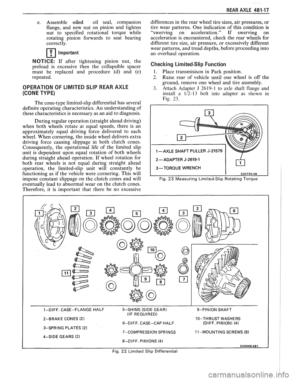
3. Attach Adapter
J 2619-1 to axle shaft flange and
install a 1/2-13 bolt into adapter as shown in
Fig. 23.
1 -AXLE SHAFT PULLER J-21579
3-TORQUE WRENCH
Fig.
23 Measuring Limited-Slip Rotating Torque
- - 1-DIFF. CASE-FLANGE HALF 5-SHIMS (SIDE GEAR) 9-PINION SHAFT
(IF REQUIRED)
2-BRAKE CONES
(2) 10-THRUST WASHERS
6-DIFF. CASE-CAP HALF (DIFF. PINION) (4)
3-SPRING PLATES (2) 7-COMPRESSION SPRINGS 11
-MOUNTING SCREWS (8) 4-SIDE GEARS (2) 8-DIFF. PINIONS (4)
Fig. 22 Limited Slip Differential
Page 283 of 1825
48-10 REAR AXLE
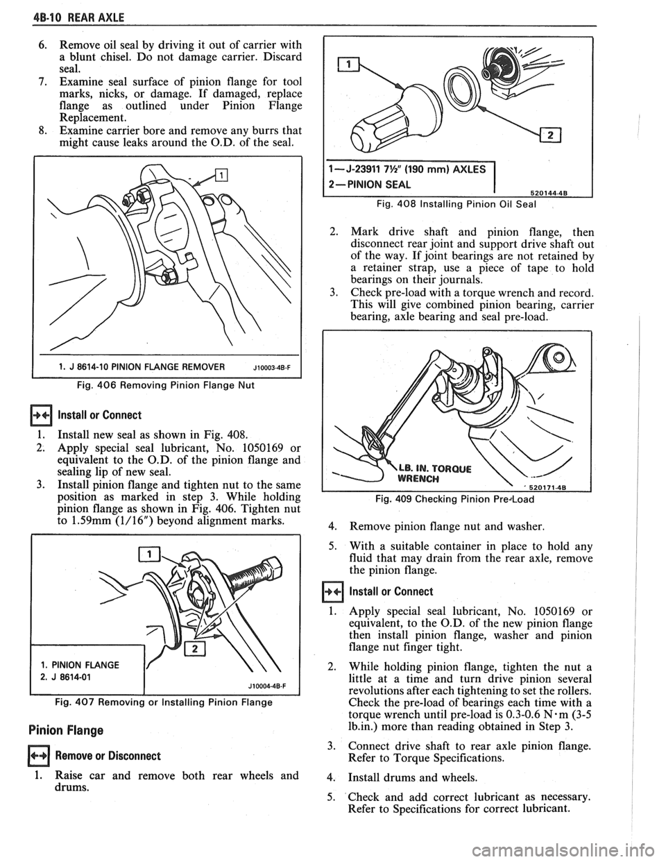
6. Remove oil seal by driving it out of carrier with
a blunt chisel. Do not damage carrier. Discard
seal,
7. Examine seal surface of pinion flange for tool
marks, nicks, or damage. If damaged, replace
flange as outlined under Pinion Flange
Replacement.
8. Examine carrier bore and remove any burrs that
might cause leaks around the O.D. of the seal.
1 1. J 8614-10 PINION FLANGE REMOVER JIOOO~-~B-F I
Fig. 406 Removing Pinion Flange Nut
Install ar Connect
1.
Install new seal as shown in Fig. 408.
2. Apply special seal lubricant, No. 1050169 or
equivalent to the O.D. of the pinion flange and
sealing lip of new seal.
3. Install pinion flange and tighten nut to the same
position as marked in step 3. While holding
pinion flange as shown in Fig. 406. Tighten nut
to
1.59mm (1/16") beyond alignment marks.
1. PINION FLANGE Fig.
408 Installing Pinion
Oil Seal
2. Mark drive shaft and pinion flange, then
disconnect rear joint and support drive shaft out
of the way. If joint bearings are not retained by
a retainer strap, use a piece of tape to hold
bearings on their journals.
3. Check pre-load with a torque wrench and record.
This will give combined pinion bearing, carrier
bearing, axle bearing and seal pre-load.
Fig. 409 Checking Pinion Predoad
4.
Remove pinion flange nut and washer.
5. With a suitable container in place to hold any
fluid that may drain from the rear axle, remove
the pinion flange.
Install or Connect
1. Apply special seal lubricant, No. 1050169 or
equivalent, to the O.D. of the new pinion flange
then install pinion flange, washer and pinion
flange nut finger tight.
2. While holding pinion flange, tighten the nut a
little at a time and turn drive pinion several
revolutions after each tightening to set the rollers.
Fig. 407 Removing or Installing Pinion Flange Check the pre-load of bearings each time with a
torque wrench until pre-load is 0.3-0.6
N-m (3-5
Pinion Flange 1b.in.) more than reading obtained in Step 3.
Remove or Disconnect 3.
Connect drive shaft to rear axle pinion flange.
Refer to Torque Specifications.
1. Raise car and remove both rear wheels and 4. Install drums and wheels.
drums. 5. Check and add correct lubricant as necessary.
Refer to Specifications for correct lubricant.
Page 288 of 1825
REAR AXLE 48-15
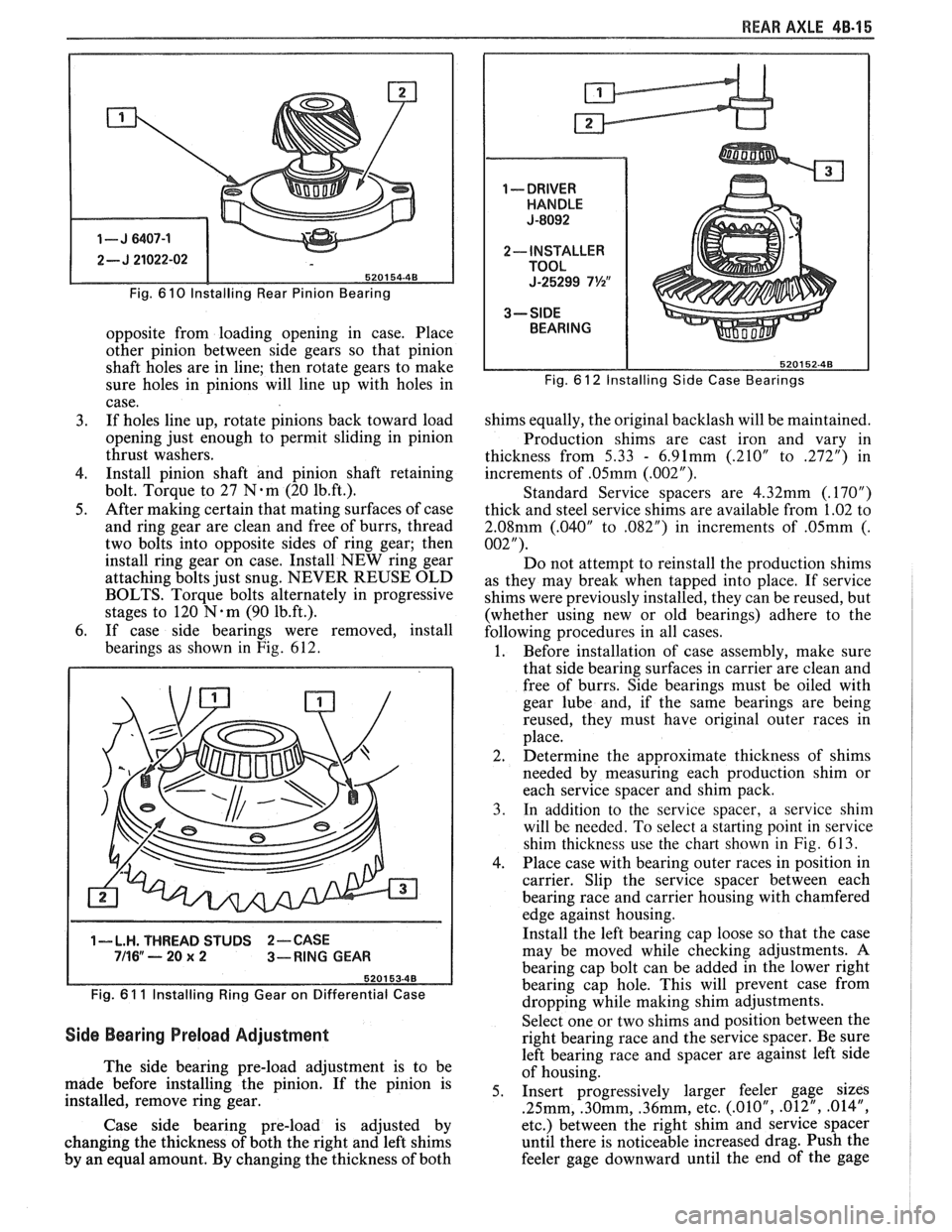
Fig. 6 10 lnstalling Rear Pinion Bearing
opposite from loading opening in case. Place
other pinion between side gears so that pinion
shaft holes are in line; then rotate gears to make
sure holes in pinions will line up with holes in
case.
3. If holes line up, rotate pinions back toward load
opening just enough to permit sliding in pinion
thrust washers.
4. Install pinion shaft and pinion shaft retaining
bolt. Torque to 27
N.m (20 1b.ft.).
5. After making certain that mating surfaces of case
and ring gear are clean and free of burrs, thread
two bolts into opposite sides of ring gear; then
install ring gear on case. Install NEW ring gear
attaching bolts just snug. NEVER REUSE OLD
BOLTS. Torque bolts alternately in progressive
stages to 120
N.m (90 1b.ft.).
6. If case side bearings were removed, install
bearings as shown in Fig. 612.
1-L.H. THREAD STUDS 2-CASE 711 6" ---- 20 x 2 3-RING GEAR
Fig.
6 1 1 lnstalling Ring Gear on Differential Case
Side Bearing Preload Adjustment
The side bearing pre-load adjustment is to be
made before installing the pinion. If the pinion is
installed, remove ring gear.
Case side bearing pre-load is adjusted by
changing the thickness of both the right and left shims
by an equal amount. By changing the thickness of both
Fig. 6 12 Installing Side Case Bearings
shims equally, the original backlash will be maintained.
Production shims are cast iron and vary in
thickness from
5.33 - 6.91mm (.210" to 272") in
increments of
.05mm (.002").
Standard Service spacers are 4.32mm (.17OU)
thick and steel service shims are available from 1.02 to
2.08mm (.040" to ,082") in increments of .05mm (.
002").
Do not attempt to reinstall the production shims
as they may break when tapped into place. If service
shims were previously installed, they can be reused, but
(whether using new or old bearings) adhere to the
following procedures in all cases.
1. Before installation of case assembly, make sure
that side bearing surfaces in carrier are clean and
free of burrs. Side bearings must be oiled with
gear lube and, if the same bearings are being
reused, they must have original outer races in
place.
2. Determine the approximate thickness of shims
needed by measuring each production shim or
each service spacer and shim pack.
3. In addition to the service spacer, a service shin1
will be needed. To select a starting point in service
shim thickness use the chart shown in
Fig. 613.
4. Place case with bearing outer races in position in
carrier. Slip the service spacer between each
bearing race and carrier housing with chamfered
edge against housing.
Install the left bearing cap loose so that the case
may be moved while checking adjustments. A
bearing cap bolt can be added in the lower right
bearing cap hole. This will prevent case from
dropping while making shim adjustments.
Select one or two shims and position between the
right bearing race and the service spacer. Be sure
left bearing race and spacer are against left side
of housing.
5. Insert progressively larger feeler gage sizes
.25mm, .30mm, .36mm, etc. (.01OU, .012", .014",
etc.) between the right shim and service spacer
until there is noticeable increased drag. Push the
feeler gage downward until the end of
the gage
Page 296 of 1825
BRAKES 5-3
DIAGNOSIS AND INSPECTION
BRAKE SYSTEM TESTING
(Figures
2 through 4)
Brakes should be tested on dry, clean, reasonably
smooth and level roadway. A true test of brake performance
cannot be made if the roadway is wet, greasy or covered
with loose dirt so that all tires do not grip the road equally.
Testing will also be affected if the roadway is crowned
which would throw the weight of the car toward the wheels
on one side. If the roadway is too rough, the wheels will tend
to bounce. Test brakes at different car speeds with both light and
heavy pedal pressure, avoid locking the brakes and sliding
the tires. Locked brakes and sliding tires do not indicate
brake efficiency, because heavily braked, but turning
wheels will stop the car in less distance than locked brakes.
More tire-to-road friction is present with a heavily braked
turning tire than with a sliding tire. The brake system is designed and balanced to avoid
locking the wheels, except at very high deceleration levels.
The shortest stopping distance and best control is achieved
without brake lock-up.
Because of high deceleration capability, a firmer pedal
may be felt at higher deceleration levels.
External Conditions That Affect Brake Performance
1. Tires. Tires having unequal contact and grip on road
will cause unequal braking. Tires must be equally
inflated and tread pattern of right and left tires must
be approximately equal.
2. Car Loading. A heavily loaded car requires more
braking effort. When a car has unequal loading, the
most heavily loaded wheels require more braking
power than others.
3. Wheel Alignment. Misalignment of the wheels, par-
ticularly excessive camber and caster, will cause the
brakes to pull to one side.
4. Front Wheel Bearings. A loose front wheel bearing
BRAKE FLUID LEAKS
With engine running at idle and the transmission in neu-
tral, depress the brake pedal and hold a constant foot pres-
sure.
If the pedal gradually falls away with the constant
pressure, the hydraulic system may be leaking. Perform a
visual check to confirm any suspected leak.
Check the master cylinder fluid levels. While a slight drop
in reservoir level does result from normal lining wear, an
abnormally low level in either reservoir indicates
a leak in
the system. The hydraulic system may be leaking either
internally or externally. See "Master Cylinder Check."
Also, the system may appear to pass this test but still have
slight leakage.
If fluid levels are normal, check the vacuum booster
pushrod length. If an incorrect length pushrod is found,
adjust or replace the
pushrod. Check the service brake
pedal travel and the parking brake adjustment.
When checking the fluid levels, the master cylinder reser-
voir may be as low as
25 mm (1 inch) from the top if the front
linings are worn. This is not abnormal.
MASTER CYLINDER CHECK
These checks will help locate some master cylinder mal-
functions. Use the Brake Diagnosis Charts to help isolate
the problem if it is not found by using these tests.
1. Check for a cracked master cylinder casting or brake
fluid around the master cylinder. Leaks are indicated
only if there is at least a drop of fluid. A damp condi-
tion is not abnormal.
2. Check for a binding pedal linkage.
3. Disassemble the master cylinder and check for swol-
len or stretched piston
seal(s). If swollen seals are
found, substandard or contaminated brake fluid
should be suspected.
If contaminated, all compo-
nents should be disassembled and cleaned. All rub-
ber components should be replaced and all the pipes
should be flushed.
permits the front wheel to tilt and lose contact with the
SUBSTANDARD OR CONTAMINATED brake shoe linings causing erratic brake operation. BRAKE FLUID
WARNING LAMP OPERATION
The brake system uses a single red "BRAKE" warning
lamp located in the instrument panel cluster. When the
ignition switch is in the "START" position, the "BRAKE"
warning lamp should come on. It should go off when the
ignition switch returns to the "RUN" position.
The following conditions will activate the "BRAKE"
warning lamp:
1. Parking brake applied. The lamp should be on when
tfie parking brake is applied and the ignition switch is
"ON."
2. Pressure differential switch detects a failure. See
"Brake Pressure Differential Warning Switch" in this
section. Improper
brake fluid, mineral oil or water in the fluid may
cause the brake fluid to boil or the rubber components to
deteriorate.
If piston cups are swollen, the rubber parts have dete-
riorated. This deterioration may also be seen by swollen
wheel cylinder piston cups on the drum brake wheels or a
swollen master cylinder cover diaphragm.
If rubber deterioration is evident, disassemble all hydrau-
lic parts and wash with alcohol. Dry these parts with com-
pressed air before assembly to keep alcohol out of the
system. Replace all rubber parts in the system, including
hoses. Check for fluid on the linings. If excessive fluid is
found, replace the linings.
If master cylinder piston seals are satisfactory, check for
leakage or excessive heat conditions. If condition is not
found, drain fluid, flush with brake fluid, fill and bleed the
system.
Page 350 of 1825
ENGINE GENERAL INFORMATION 6-5
INSTRUMENT PANEL OIL WARNING LAMP "ON" AT IDLE
1. Oil cooler, or oil or cooler line restricted. Remove 2. Oil pump pressure low. See oil pump repair
restrictions in cooler or cooler line. procedures
in Section
6A.
ENGINE COMPRESSION EST
COMPRESSION TEST
Important
e Disconnect the "BAT." terminal from the - HE1 distributor or ignition module.
To determine if the valves or pistons are at fault,
a test should be made to determine the cylinder
compression pressure. When checking cylinder
compression, the throttle and choke should be open, all
spark plugs removed, and the battery at or near full
charge. The lowest reading cylinder should not be less
than
70% of the highest and no cylinder reading
should be less than
689 kPa (100 PSI). This
should be done with four
"puffs" per
cylinder.
Normal - Compression builds up quickly and
evenly to specified compression on each cylinder.
Piston Rings - Compression low on first
stroke, tends to build up on following strokes, but does
not reach normal. Improves considerably with addition
of oil.
Valves - Low on first stroke, does not tend to
build up on following strokes. Does not improve much
with addition of oil.
Use approximately three squirts from a plunger
type oiler.