1988 PONTIAC FIERO jack points
[x] Cancel search: jack pointsPage 245 of 1825

4A-4 PROPELLER SHAFT
PROPELLER SHAFT BALANCING
Hose Clamp Method
Figures 4A- 1 1 thru 4A-13
1. Place the vehicle on a twin post hoist so that the
rear of the vehicle is supported on the rear axle
housing and the rear wheels are free to rotate.
Remove both rear wheel assemblies and reinstall
wheel lug nuts with flat sides next to
drums/discs.
2. Mark and number propeller shaft at four (4)
points 90 degrees apart at rear of shaft just
forward of balance weight, as shown.
3. Install two (2) hose clamps on the rear of the
propeller shaft and slide them rearward until the
clamps stop at the nearest balance weight welded
to the tube. Align both clamps at any one of the
four marks made on shaft in Step 2 and tighten.
Be sure sufficient clearance is maintained so that
clamp heads do not contact floor pan of vehicle
when axle is in contact with rebound bumper in
frame. In order to gain sufficient clearance, it
may be necessary to position the clamps over the
balance weights.
4. Run the vehicle through the speed range to 80-90
MPH (130-145
Km/h) and note amount of
imbalance.
CAUTION: All persons should stay
clear of universal joint and balance
weight areas to avoid possible injury.
Do not run on hoist for extended
periods due to the danger of
overheating the transmission or
engine.
5. Loosen clamps and rotate clamp heads 90 degrees
to the next mark on a propeller shaft. Tighten
clamps and repeat Step 4.
6. Repeat Step 5 until car has been run with clamp
heads located at all four marks on shaft.
7. Position clamps at point of least imbalance.
Rotate the clamp heads away from each other 45
degrees (one on each side of the position), as
shown. Run the vehicle and note if imbalance has
improved.
In some cases it may be necessary to use one
clamp or possibly three clamps in order to obtain
a good balance. Replace shaft if three hose clamps
do not improve the imbalance.
8. Continue to rotate the clamps apart in smaller
angular increments until the imbalance is at its
minimum.
9. Reinstall wheel assemblies and road test the
vehicle for final check of balance. A minimal
vibration felt in the vehicle on the hoist may not
show up during a road test.
Strobe Light Method
Figures 461- 1 1, $A- 14, and 4A- 15
If a wheel balancer of the strobe light type is
available, the use of such a unit will facilitate the
balancing of the propeller shaft. The balance pick-up
unit should be placed directly under the nose of the
rear axle carrier and as far forward as possible. 1.
Place
the vehicle on a twin post hoist so the rear of
the vehicle is supported on the rear axle housing and
the rear wheels are free to rotate. Lower rear hoist
and allow axle to rest on jackstands. The groove in
the rear hoist fixture could clamp the axle and de-
stroy the sensitivity of the operation. Remove both
rear wheel assemblies and reinstall wheel lug nuts
with flat sides next to the
drums/rotors.
2.
Mark and number drive shaft at 4 points 90
degrees apart at rear of shaft just forward of
balance weights, as shown.
3. Place the strobe light wheel balancer pick-up
under the nose of the carrier.
4. Run vehicle in gear at the speed where the
distrubance is at its peak, allow the driveline to
stabilize by holding at a constant speed. Point
strobe light up at the spinning propeller shaft and
note position of one of the reference numbers.
Shut off engine and position the propeller shaft so
the reference numbers will be in the same position
as was noted while the shaft was rotating.
When strobe light flashed, the heaviest point of
the shaft was at the bottom (6 o'clock). To
balance the propeller shaft, it would be necessary
to apply the balancing weights (hose clamps) 180
degrees away from the heaviest point or at the top
of the propeller shaft (12 o'clock).
5. Install two screw-type hose clamps on the
propeller shaft as close to the rear as possible.
Position both clamp heads 180 degrees from the
heaviest point of drive shaft as indicated by strobe
light. Tighten clamps.
NOTICE: Be sure sufficient clearance is
maintained so clamp heads do not contact floor
pan of vehicle when axle is in contact with rebound
bumper on frame. In order to gain. sufficient
clearance, it may be necessary to position the
clamps over the balance weights.
6. Run vehicle through the speed range 80-90
M.P.
H. (130-145 Km/h). If disturbance is gone,
nothing further need be done on the hoist. If the
disturbance is not gone and the strobe light shows
the clamp heads at the bottom (6 o'clock) of the
shaft, go to Step
7. If the strobe light shows the
two clamp heads at the top of the shaft, add one
more hose clamp and recheck. If the strobe light
shows the three clamp heads at the top of the
shaft, remove the propeller shaft and
reindex it
180 degrees on the rear axle pinion companion
flange. Recheck with no clamps. Repeat balance
starting with Step 5. If the shaft still needs more
than three hose clamps at the same clock position,
replace it. If the clamps are also 180 degrees from
their original position after the propeller shaft
was reindexed 180 degrees, the rear axle pinion
companion flange is out of balance and must be
replaced. DO NOT use more than three hose
clamps to balance the shaft. If the strobe light
shows the hose clamps at the bottom of the shaft,
but the disturbance still exists, go to Step
7.
Page 255 of 1825

4819 REAR AXLE
bears against the inner race of the front bearing and a
shoulder on the pinion stem. This spacer is used to
enable accurate bearing pre-load adjustment and
maintain a pre-load on both front and rear pinion
bearings, Adjustment of the fore and aft position of the
pinion is obtained by placing a shim between the rear
pinion bearing cup and axle housing. The differential
case is of two-piece construction and is supported in
the carrier by two tapered roller side bearings. Pre-load
rear axle case by inserting shims between the bearings
and the carrier. The rear axle case assembly is
positioned for proper ring gear to pinion backlash by
varying the shim thickness from side to side. The ring
gear is bolted to the case. Two side gears have splined
bores for driving the axle shafts. They are positioned
to turn in counterbored cavities in the case. The four
rear axle pinions have smooth bores and are held in
position by a pinion cross shaft, mounted and locked
in the rear axle case. All six gears are in mesh with each
other and because the pinion gears turn freely on their
shaft, they act as idler gears when the rear wheels are
turning at different speeds. The pinions and side gears
are backed by steel thrust washers.
LIMITED-SLIP REAR AXLE
The operation of the Limited-Slip differential is
the same as the standard differential, except that there
is additional friction provided by the conical clutches.
Under ordinary driving and cornering conditions, the
cones slip, allowing the outside wheel to turn faster
than the inner. Under poor traction conditions, such as
ice, snow, or loose gravel under one driving wheel, the
increased friction provided by the cones increases the
driving torque available to the wheel with the better
traction. The cones are spring loaded to provide the
increased driving torque under extremely low traction
conditions.
Operation
When the vehicle turns a corner, the outer rear
wheel must turn faster than the inner wheel. The inner
wheel, turning slower than the outer wheel, slows its
differential side gear (as the axle shaft is splined to the
side gear) and the differential pinion gears will roll
around the slowed differential side gear, driving the
other differential side gear and wheel faster.
DIAGNOSIS AND TESTING
Many noises reported as coming from the rear
axle assembly actually originate from other sources
such as tires, road surfaces, front wheel bearings, axle
bearing, engine, transmission, muffler or body
drumming. A thorough and careful check should be
made to determine the source of the noise before
disassembling the rear axle. Noise which originates in
other places cannot be corrected by adjustment or
replacement of parts in the differential. It should also
be remembered that rear axle gears, like any other
mechanical device, are not absolutely quiet and should
be accepted as being commercially quiet unless some
abnormal noise is present.
To make a systematic check for axle noise under
standard conditions, observe the following:
1. Select a level smooth asphalt road to reduce tire
noise and body drumming.
2. Check rear axle lubricant to assure correct level,
then drive car far enough to thoroughly warm up
rear axle lubricant, approximately 10 miles.
3. Note speed and RPM at which noise occurs. Stop
car and put transmission in neutral. Run engine
slowly up and down through engine speeds,
corresponding to car speed at which noise was
most pronounced, to determine if it is caused by
exhaust, muffler roar or other engine conditions.
4. Tire noise changes with different road surfaces,
but rear axle noise does not. Temporarily
inflating all tires to approximately 50 pounds
pressure
for test purposes only will materially
alter noise caused by tires, but will not affect noise
caused by rear axle. Rear axle noise usually stops
when coasting at speeds under 30 miles per hour;
however, tire noise continues, but with lower
tone, as car speed is reduced. Rear axle noise
usually changes when comparing acceleration
and coast, but tire noise remains about the same.
Distinguish between tire noise and rear axle noise
by noting if noise varies with various speeds or
sudden acceleration and deceleration; exhaust
and axle noise show variations under these
conditions while tire noise remains constant and
is more pronounced at speeds of 20 to 30 miles
per hour. Further check for tire noise by driving
car over smooth pavements or dirt roads (not
gravel) with tires at normal pressure. If noise is
caused by tires, it will noticeably change or
disappear and reappear with changes in road
surface.
5. Loose or rough front wheel bearings will cause
noise which may be confused with rear axle
noises; however, front wheel bearing noise does
not change when comparing drive and coast.
Light application of brakes while holding car
speed steady will often cause wheel bearing noise
to diminish, as this takes some weight off the
bearing. Front wheel bearings may be easily
checked for noise by jacking up the wheels and
spinning them, also by shaking wheels to
determine if bearings are loose.
6. Rear suspension rubber bushings and spring
insulators dampen out rear axle noise when
correctly installed. Check to see that no metallic
contact exists between the spring and spring seat
opening in frame or between upper and lower
control arm bushings and frame or axle housing
brackets. The track bar and torque arm must be
bolted securely. Metal-to-metal contact at those
points may result in telegraphing road noise and
normal axle noise which would not be
objectionable if dampened by bushings.
AXLE NOISES
After the noise has been determined as being in
the axle by following the above appraisal procedure,
the type of axle noise should be determined to aid in
making repairs if necessary.
Page 276 of 1825

REAR AXLE 4B-3
Noise which originates in other places cannot be
corrected by adjustment or replacement of parts in the
differential. It should also be remembered that rear
axle gears, like any other mechanical device, are not
absolutely quiet and should be accepted as being
commercially quiet unless some abnormal noise is
present.
To make a systematic check for axle noise under
standard conditions, observe the following:
1. Select a level smooth asphalt road to reduce tire
noise and body drumming.
2. Check rear axle lubricant to assure correct level,
then drive car far enough to thoroughly warm up
rear axle lubricant.
3. Note speed and RPM at which noise occurs. Then
stop car and with automatic transmission in neutral,
run engine slowly up and down through engine speeds, corresponding to car speed at which noise
was most pronounced, to determine if it is caused by
exhaust, muffler roar or other engine conditions.
4. Tire noise changes with different road surfaces,
but rear axle noise does not. Temporarily
inflating all tires to approximately 50 pounds
pressure for
test purposes only will materially
alter noise caused by tires, but will not affect noise
caused by rear axle. Rear axle noise usually stops
when coasting at speeds under 30 miles per hour;
however, tire noise continues, but with lower
tone, as car speed is reduced. Rear axle noise
usually changes when comparing acceleration
and coast, but tire noise remains about the same.
Distinguish between tire noise and rear axle noise
by noting if noise varies with various speeds or
sudden acceleration and deceleration; exhaust
and axle noise show variations under these
conditions while tire noise remains constant and
is more pronounced at speeds of 20 to 30 miles
per hour. Further check for tire noise by driving
car over smooth pavements or dirt roads (not
gravel) with tires at normal pressure. If noise is
caused by tires, it will noticeably change or
disappear and reappear with changes in road
surface.
5. Loose or rough front wheel bearings will cause
noise which may be confused with rear axle
noises; however, front wheel bearing noise does
not change when comparing drive and coast.
Light application of brakes while holding car
speed steady will often cause wheel bearing noise
to diminish, as this takes some weight off the
bearing. Front wheel bearings may be easily
checked for noise by jacking up the wheels and
spinning them, also by shaking wheels to
determine if bearings are loose.
6. Rear suspension rubber bushings and spring
insulators dampen out rear axle noise when
correctly installed. Check to see that no metallic
contact exists between the spring and spring
opening in frame or between upper and lower
control arm bushings and frame or axle housing
brackets.
Metal-to-metal contact at those points
may result in telegraphing road noise and normal axle
noise which would not be objectionable if
dampened by bushings.
AXLE NOISES
Gear Noise
After the noise has been determined as being in
the
axle by following the above appraisal procedure,
the type of axle noise should be determined to aid in
maki~~g repairs if necessary.
Gear noise (whine) is audible from 20 to
55 mph
under four driving conditions:
1. Drive - Acceleration or heavy pull.
2. Road Load - Car driving load or constant speed.
3. Float
- Using
enough throttle to keep the car from
driving the engine
- car slows down gradually but
engine still pulls slightly.
4. Coast
- Throttle closed and car in gear. Gear
noise most frequently has periods where noise is
more prominent, usually 30 to 40 mph and 50 to
55 mph.
Bearing Noise
Bad bearings generally produce more of a rough
growl or grating sound, rather than the whine typical
of gear noise. Bearing noise frequently "wow-wows" at
bearing rpm, indicating a defective pinion or rear axle
case side bearing. This noise could easily be confused
with rear wheel bearing noise. Inspect and replace as
required.
Rear Wheel Bearing Noise
A rough rear wheel bearing produces a noise
which continues with car coasting at low speed and
transmission in neutral. Noise may diminish some by
gentle braking. With rear wheels jacked up, spin rear
wheels by hand while listening at hubs for evidence of
rough (noisy) wheel bearing.
I(noclc At Low Speeds
Low speed knock can be caused by worn
universal joints or a side gear hub counterbore in a case
that has worn oversize. Inspect and replace universal
joint or case and side gear as required.
Baclclash Clunk
Excessive clunk with acceleration and
deceleration is caused by worn differential pinion shaft,
excessive clearance between axle shaft and side gear
splines, excessive clearance between side gear hub and
counterbore in case worn pinion and side gear teeth,
worn thrust washers and excessive drive pinion and
rear gear backlash. Remove worn parts and replace as
required, selecting close fitting parts when possible.
Adjust pinion and ring gear backlash.
REAR AXLE STANDARD AND LIMITED-SLIP
1. Noise is the same in "Drive" or "Coast".
a. Road noise.
b. Tire noise.
c. Front wheel bearing noise.
Page 405 of 1825

6A3-26 V-8 ENGINE
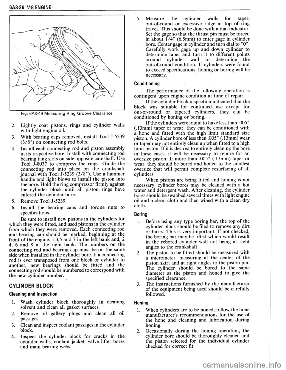
Fig. 6A3-49 Measuring Ring Groove Clearance
2. Lightly coat pistons, rings
and cylinder walls
with light engine oil.
3. With bearing caps removed, install Tool J-5239
(3/8") on connecting rod bolts.
4. Install
each connecting rod and piston assembly
in its respective bore. Install with connecting rod
bearing tang slots on side opposite camshaft. Use
Tool
5-8037 to compress the rings. Guide the
connecting rod into place on the crankshaft
journal with Tool
5-5239 (3/8"). Use a hammer
handle and light blows to install the piston into
the bore. Hold the ring compressor firmly against
the cylinder block until all piston rings have
entered the cylinder bore.
5. Remove Tool J-5239.
6. Install the bearing caps and torque nuts to
specifications.
Be sure to install new pistons in the cylinders for
which they were fitted, and used pistons in the cylinder
from which they were removed. Each connecting rod
and bearing cap should be marked, beginning at the
front of the engine.
1,3,5 and 7 in the left bank and, 2
4, 6 and 8 in the right bank. The numbers on the
connecting rod and bearing cap must be on the same
side when installed in the cylinder bore. If a connecting
rod is ever transposed from one block or cylinder to
another, new bearings should be fitted and the
connecting rod should be numbered to correspond with
the new cylinder number.
CYLINDER BLOCK
Cleaning and Inspection
1. Wash cylinder block thoroughly in cleaning
solvent and clean all gasket surfaces.
2. Remove oil gallery plugs and clean all oil
passages.
3. Clean and inspect coolant passages in the cylinder
block.
4. Inspect the cylinder block for cracks in the
cylinder walls, coolant jacket, valve lifter bores
and main bearing webs. 5.
Measure the cylinder walls for taper,
out-of-round or excessive ridge at top of ring
travel. This should be done with a dial indicator.
Set the gage so that the thrust pin must be forced
in about
1/4" (6.5mm) to enter gage in cylinder
bore. Center gage in cylinder and turn dial to
"0".
Carefully work gage up and down cylinder to
determine taper and turn it to different points
around cylinder wall to determine the
out-of-round condition. If cylinders were found
to exceed specifications, honing or boring will be
necessary.
Conditioning
The performance of the following operation is
contingent upon engine condition at time of repair.
If the cylinder block inspection indicated that the
block was suitable for continued use except for
out-of-round or tapered cylinders, they can be
conditioned by honing or boring.
If the cylinders were found to have less than
.005"
(.13mm) taper or wear, they can be conditioned with
a hone and fitted with the high limit standard size
piston. A cylinder bore of less then
.005" (. 13mm) wear
or taper may not entirely clean up when fitted to a high
limit piston. If it is desired to entirely clean up the bore
in these cases, it will be necessary to
rebore for an
oversize piston. If more than
.005" (. 13mm) taper or
wear, they should be bored and honed to the smallest
oversize that will permit complete resurfacing of all
cylinders.
When pistons are being fitted and honing is not
necessary, cylinder bores may be cleaned with a hot
water and detergent wash. After cleaning, the cylinder
bores should be swabbed several times with light engine
oil and a clean cloth and then wiped with a clean dry
cloth.
Boring
1. Before using any type boring bar, the top of the
cylinder block should be filed to remove any dirt
or burrs. This is very important. If not checked,
the boring bar may be tilted which would result
in the
rebored cylinder wall not being at right
angles to the crankshaft.
2. The
piston to be fitted should be measured with
a micrometer, measuring at the center of the
piston skirt and at right angles to the piston pin.
The cylinder should be bored to the same
diameter as the piston and honed to give the
specified clearance.
3.
The instructions furnished by the manufacturer
of the equipment being used should be carefully
followed.
Honing
1. When cylinders are to be honed, follow the hone
manufacturer's recommendations for the use of
the hone and cleaning and lubrication during
honing.
2. Occasionally during the honing operation, the
cylinder bore should be thoroughly cleaned and
the piston selected for the individual cylinder
checked for correct fit.