1988 PONTIAC FIERO alternator
[x] Cancel search: alternatorPage 361 of 1825
6A2-10 2.8 LITER V-6
5. Remove air management valve from A.I.R.
pump. 6. Remove alternator bracket.
7. Remove exhaust manifold bolts.
8. Disconnect air management hose.
9. Remove manifold.
Installation (Right)
1. Clean
mating surfaces on manifold and head,
then install manifold in position and install bolts.
2. Torque
manifold bolts to 34
N-m (25 ft. lbs.).
3. Attach air management hose.
4. Raise vehicle.
5. Install exhaust pipes.
6. Lower vehicle.
7. Install alternator bracket.
8. Install air management valve.
7. Connect battery.
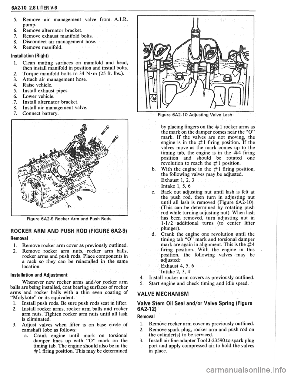
Figure 6A2-9 Rocker Arm and Push Rods
ROCKER ARM AND PUSH ROD (FIGURE 6A2-9)
Removal
1. Remove
rocker arm cover as previously outlined.
2. Remove rocker arm nuts, rocker arm balls,
rocker arms and push rods. Place components in
a rack so they can be reinstalled in the same
location.
lnstallation and Adiustment
Whenever new rocker arms and/or rocker arm
balls are being installed, coat bearing surfaces of rocker
arms and rocker balls with a thin even coating of
"Molykote" or its equivalent.
1. Install push rods. Be sure push rods seat in lifter.
2. Install rocker arms, rocker arm balls and rocker
arm nuts. Tighten rocker arm nuts until all lash
is eliminated.
3. Adjust valves when lifter is on base circle of
camshaft lobe as follows:
a. Crank engine until mark on torsional
damper lines up with
"0" mark on the
timing tab. The engine should also be in the
# 1 firing position. This may be determined
Figure 6A2-10 Adjusting Valve Lash
by placing fingers on the # 1 rocker arms as
the mark on the damper comes near the
"0"
mark. If the valves are not moving, the
engine is in the
# 1 firing position. If the
valves move as the mark comes up to the
timing tab, the engine is in the
#4 firing
position and should be rotated one
revolution to reach the
# 1 position.
b. With the
engine in the
# 1 firing position,
the following valves may be adjusted.
Exhaust 1, 2, 3
Intake 1, 5,
6
c. Back
out adjusting nut until lash is felt at
the push rod, then turn in adjusting nut
until all lash is removed (Figure
6A2-10).
(This can be determined by rotating push
rod while turning adjusting nut). When lash
has been removed, turn adjusting nut in
1-1/2 additional turns (to center lifter
plunger).
d. Crank the
engine one revolution until the
timing tab
"0" mark and torsional damper
mark are again in alignment. This is the
#4
firing position. With the engine in this
position, the following valves may be
adjusted:
Exhaust 4, 5,
6
Intake 2, 3, 4
4.
Install rocker arm covers as previously outlined.
5. Start
engine and check timing and idle speed.
VALVE MECHANISM
Valve Stern Oil Seal and/or Valve Spring (Figure
6A2-12)
Removal
1. Remove rocker
arm cover as previously outlined.
2. Remove spark plug, rocker arm and push rod on
the
cylinder(s) to be serviced.
3. Install
air line adapter Tool J-23590 to spark plug
port and apply compressed air to hold the valves
in place.
Page 387 of 1825
6A3-8 V-8 ENGINE
10. Remove exhaust pipe nuts.
1 1. Lower vehicle.
12. Remove manifold bolts.
13. Remove manifold.
Installation
1. Clean mating surfaces on manifold and head,
then install manifold in position and install bolts
finger tight.
2. Torque bolts to specifications.
3. Reverse removal procedures.
4. Adjust necessary drive belts.
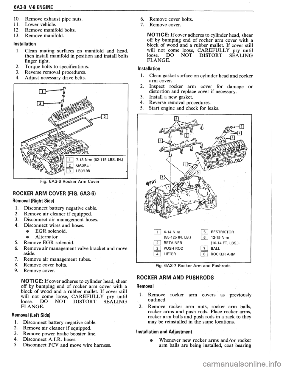
P
IN.)
Fig. 6A3-6 Rocker Arm Cover
ROCKER ARM COVER (FIG. 6A3-6)
Removal (Right Side)
1. Disconnect battery negative cable.
2. Remove air cleaner if equipped.
3. Disconnect air management hoses.
4. Disconnect wires and hoses.
EGR solenoid.
e Alternator
5. Remove EGR solenoid.
6. Remove air management valve bracket and move
aside.
7. Remove air management tubes.
8. Remove cover bolts.
9. Remove cover.
N OTI G E: If cover adheres to cylinder head, shear
off by bumping end of rocker arm cover with a
block of wood and a rubber mallet. If cover still
will not come loose, CAREFULLY pry until
loose. DO NOT DISTORT SEALING
FLANGE.
Removal (Left Side)
1. Disconnect battery negative cable.
2. Remove air cleaner if equipped.
3. Remove Power brake booster line.
4. isc connect A.I.R. hoses.
5. Disconnect PCV and move wire harness.
6. Remove cover bolts.
7. Remove cover.
NOTICE: If cover adheres to cylinder head, shear
off by bumping end of rocker arm cover with a
block of wood and a rubber mallet. If cover still
will not come loose, CAREFULLY pry until
loose. DO NOT DISTORT SEALING
FLANGE.
lnstallation
1. Clean gasket surface on cylinder head and rocker
arm cover.
2. Inspect rocker arm cover for damage or
distortion and replace cover if necessary.
3. Install a new gasket.
4. Reverse removal procedures.
5. Start engine and check for leaks.
6-14 N.m RESTRICTOR
(55-125 IN.
LB.) 161 13-19 N,rn - 1 RETAINER (10-14 FT. LBS.)
/ PUSH ROD a BALL
a LIFTER 1 ROCKER ARM
Fig. 6A3-7 Rocker Arm and Pushrods
ROCKER ARM AND PUSHRODS
Removal
1. Remove rocker arm covers as previously
outlined.
2. Remove rocker arm nuts, rocker arm balls,
rocker arms and push rods. Place rocker arms,
rocker arm balls and push rods in a rack to they
may be reinstalled in the same locations.
Installation and Adjustment
e Whenever new rocker arms and/or rocker
arm balls are being installed, coat bearing
Page 658 of 1825
DRIVEABILITY AND EMISSIONS 2.8L (VIN S) 6E3-A-5
ECM
BRAKE SWITC
BACK
VIEW OF
AIR DIVERT SOLENOID
MANUALITRANS
IGNITION 12V
TANMIHT 250 ALTERNATOR
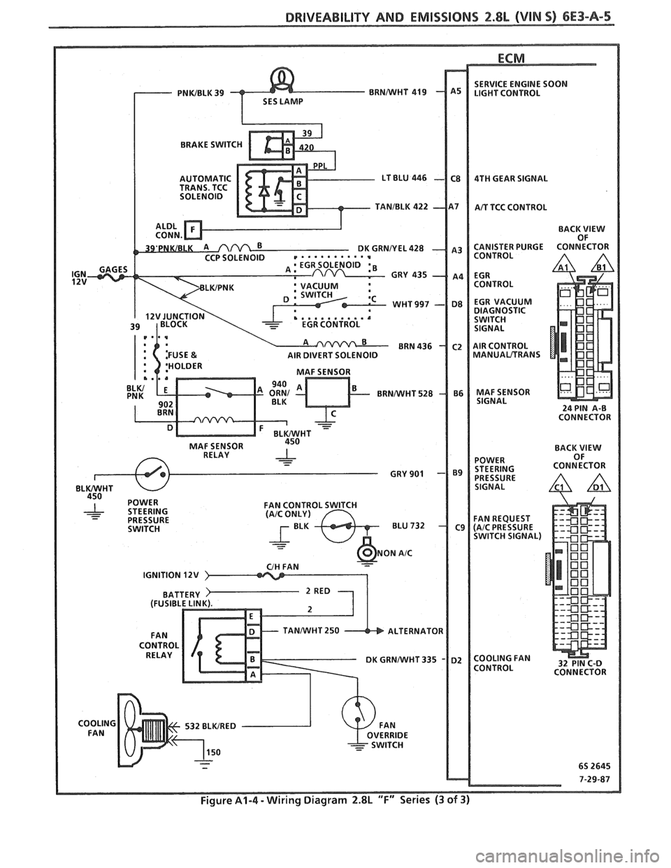
Figure A1-4 - Wiring Diagram 2.8L "F" Series (3 of 3)
Page 797 of 1825
CONNECTOR
TO ALTERNATOR
I.P.CONNECTOR
DK GRNNVHT 335
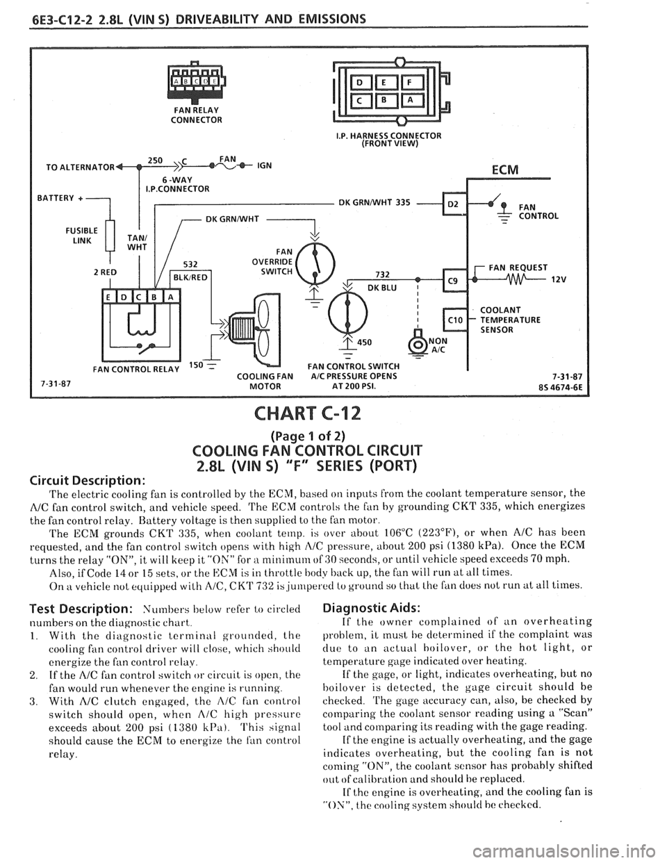
CHART C-12
(Page 1 of 2)
COOLING FAN CONTROL CIRCUIT
2.8L (VIN S) "F" SERIES (PORT)
Circuit Description:
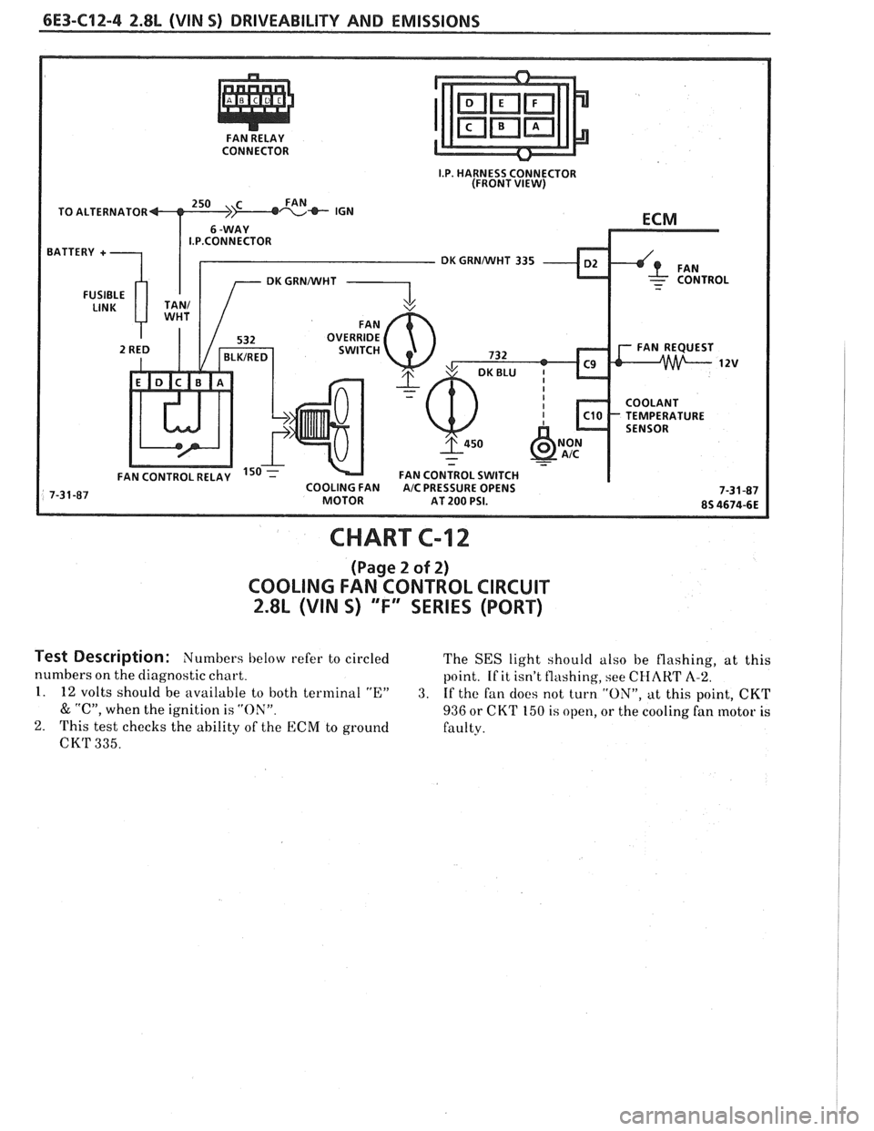
'I'he electric cooling fan is controlled by the ECM, based on inputs from the coolant temperature sensor, the
NC fan control switch, and vehicle speed. 'I'he ECM controls the f~in by grounding CKT 335, which energizes
the fan control relay. Battery voltage is then supplied to the fan motor.
The ECM grounds
CKT 335, when coolant temp. is over about 106°C (223"F), or when AIC has been
requested, and the fan control switch opens with high
I\/C pressure, about 200 psi (1380 kPa). Once the ECM
turns the relay "ON", it will keep it "ON" for a nlinirnum of GO seconds, or until vehicle speed exceeds 70 mph.
Also, if Code
14 or 15 sets, or the ECM is in throttle body back up, the fan will run at all times.
On
kt vehicle not equipped with A/C, CK'I' 732 is,ju~rlperetl to ground so that Lhe fan does not run at all times.
Test Description: Numbers below refer to circled
numbers on the diagnostic chart,.
1. With the diagnostic terminal grounded, the
cooling
fan control driver will close, which should
energize the fan control
relay.
2. If the A/C fan control switch or circuit is open, the
fan would run whenever the engine is running.
3. With AIC clutch engaged, the i\lC fan control
switch should open, when
A/C high pressure
exceeds about
200 psi ( 1380 k13a). This signal
should cause the
ECM to energize the ran control
relay.
Diagnostic Aids:
If the owner complained of an overheating
problem, it
rnust he determined if the complaint was
clue to an actuill hoilover, or the hot light, or
temperature gage indicated over heating.
If the gage, or light, indicates overheating, but no
hoilover is detected, the gage circuit should he
checked.
'I'he gage accuracy can, also, be checked by
comparing the coolant sensor reading using a "Scan"
tool and comparing its reading with the gage reading.
If the engine is actually overheating, and the gage
indicates overheating, but the cooling fan is not
coming "ON", the coolant sensor has probably shifted
out
ofcalibration and should be replaced.
If
the engine is overheating, and the cooling fan is
"ON", the cooling system should hc checked.
Page 799 of 1825
6E3-C12-4 2.8L (VIN S) DRIVEABILITY AND EMISSIONS
I.P. HARNESS CONNECTOR
(FRONT VIEW)
TO ALTERNATOR
DK GRNNVHT 335
FAN CONTROL SWITCH
CHART C-12
(Page 2 of 2)
COOLING FAN CONTROL CIRCUIT
2.8L (VIN S) "F" SERIES (PORT)
Test Description: Numbers below refer to circled
The SES light should also be flashing, at this
numbers on the diagnostic chart.
point. If it isn't flashing, see
CHART A-2.
1. 12 volts should be available to both terminal "E" 3. If the fan docs not turn "ON", at this point, CKT
& "C", when the ignition is "ON". 936 or CKT 150 is open, or the cooling fan motor is
2. This test checks the ability of the ECM to ground
faulty.
CK'I' 335.
Page 898 of 1825
DRIVEABILITY AND EMISSIONS 5.OL (VIN F) & 5.7L (VIN 8) 6E3-C2-11
3. Separate left hand fuel rail and plug assembly
(200) from right hand fuel rail and plug assembly
(220).
4. Bracket-to-rail
attaching screw assembly (256),
two bracket-to-base attaching screw assemblies
(258) and pressure regulator and base assembly
bracket
(255).
5. Screw
assembly (235), which attaches fuel outlet
tube to right hand rail (220).
6. Base to right hand rail screw assembly (275).
7. Pressure regulator and base assembly (240) from
right hand rail assembly (220).
8. Rotate regulator and base assembly to remove
from fuel outlet tube.
9. Base to rail connector (250).
10. O-ring seals and discard:
@ Connector (252).
@ Fuel outlet tube (224).
@ Rear crossover tube (267).
@ Front crossover tube (232).
Important
When removing O-ring seals, note locations and
sizes, to assure correct replacement and re-
assembly.
Inspect
@ O-rings and sealing surfaces, for damage that
could prevent proper sealing.
- Replace any damaged O-ring seals.
n Install or Connect
1. Lubricate with engine oil, and install O-ring seals:
@ Connector (252).
@ Fuel outlet tube (224).
@ Rear crossover tube (267).
@ Front crossover tube (232).
Base-to-rail connector (250) in pressure regulator
and base assembly (240).
Regulator and base assembly on fuel outlet tube.
Rotate the regulator and base assembly to install
base to rail connector
(250) into right hand rail
assembly
(220).
Base to right hand rail screw assembly (275).
Pressure regulator and base assembly bracket
(2551, two brackets to base attaching screw
assembly (258) and bracket to rail attaching screw
assembly (256).
Rear bracket attaching screw assembly
(235).
Left hand rail and plug assembly (2001, with front
and rear crossover tubes (230) and
265), to right
hand rail and tube assembly
(220).
Rear crossover tube retainer (270) and retainer to
base screw assembly
(273).
240PRESSUREREGUbATORAND
BASE ASSEMBLY
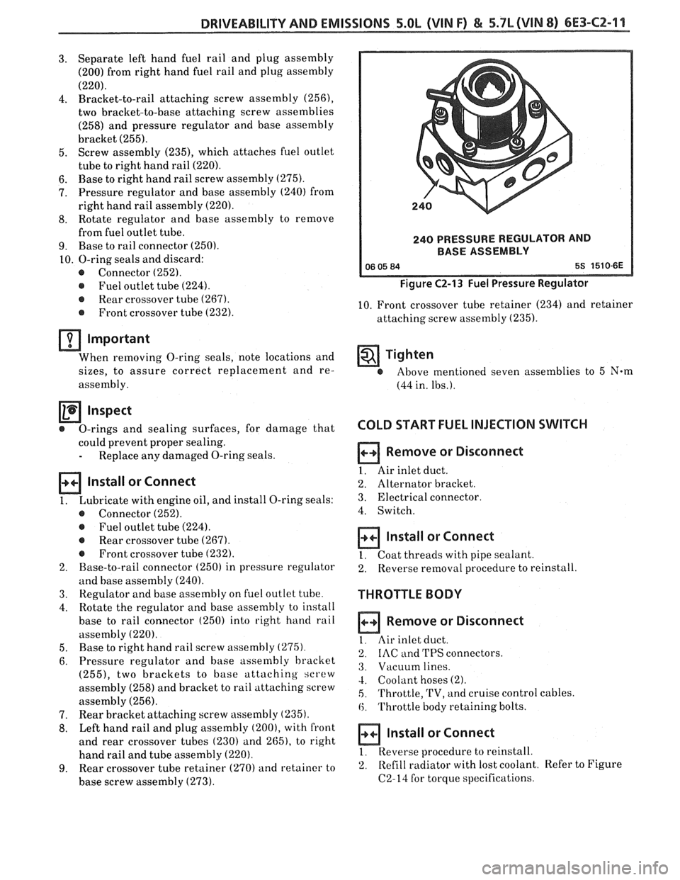
Figure C2-13 Fuel Pressure Regulator
10. Front crossover tube retainer (234) and retainer
attaching screw assembly
(235).
Tighten
@ Above mentioned seven assemblies to 5 N-m
(44 in. lbs.).
COLD START FUEL INJECTION SWITCH
Remove or Disconnect
1. Air inlet duct.
2. Alternator bracket.
3. Electrical connector
4. Switch.
Install or Connect
1. Coat threads with pipe sealant.
2. Reverse
removal procedure to reinstall.
THROTTLE BODY
Remove or Disconnect
I. Air inlet duct.
2. IAC and 'I'PS connectors.
3. Vacuum lines.
4. Coolant hoses (2).
5. 'I'hrottle, 'L'V, and cruise control cables.
6. Throttle body retaining bolts.
a Install or Connect
1, Reverse procedure to reinstall.
2. Refill
radiator with lost coolant. Refer to Figure
C2-14 for torque specifications.
Page 1554 of 1825
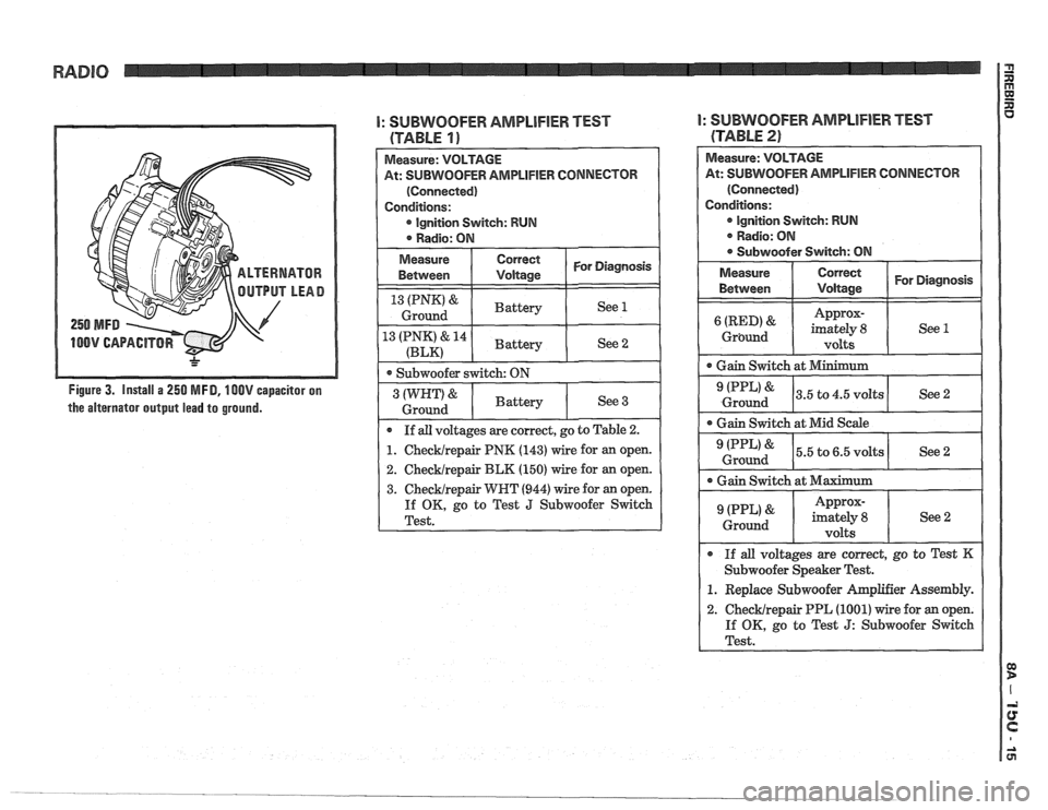
Figure 3. Install a 250 MFD, 100V capacitor on
the alternator output lead to ground.
I: SUBWOOFER AMPLIFIER TEST
(TABLE 19
2. Checklrepair BLK (150) wire for an open.
3. Checklrepair WRT (944) wire for an open.
If OK, go to Test J Subwoofer Switch
Test.
I: SUBWOOFER AMPLlFlER TEST
(TABLE
2)
Measure: VOLTAGE
At:
SUBWOOFER AMPLIFIER CONNECTOR
(Connected)
Conditions: Ignition
Svvitch: RUN
. Radio: ON
@ Subwoofer Switch: ON
Measure Correct
I Vdtaae I For Diagnosis
Between
Approx-
Grbund
Ground I See2 I -- -
Gain Switch at Mid Scale
0 Gain Switch at Maximum I Approx- (PPL' ' imately 8
Ground
volts
0 If all voltages are correct, go to Test K
Subwoofer Speaker Test.
1. Replace Subwoofer hplifier Assembly.
2. ChecMrepair PPL (1001) wire for an open.
If OK, go to Test
J: Subwoofer Switch
Test.
Page 1613 of 1825

842-2 INSTRUMENT PANEL. GAGES & CONSOLE
Pinion Gear
The PINION GEAR is attached to the
traaasmission/transaxle output shaft and rotates in
proportion to the speed of the car. This rotation is
transferred from the pinion gear to the speedometer
head by the speedometer cable.
Photo Speed Sensor
On vehicles that use a mechanical drag-cup
speedometer, the PHOTO SPEED SENSOR is
inserted into the frame of the mechanical speedometer
to provide an electrical feedback to the ECM that
represents vehicle speed. The ECM needs to know how
fast the car is traveling in order to control and operate
the cruise control, cooling fan, and transmission and
evaporative systems.
The photo speed sensor is made up of two special
electronic devices: a Eight-Emitting Diode (LED) and
a photo transistor (a light-sensitive amplifying device).
In the mechanical speedometer, there is a reflective
blade attached to the rotating magnet that is polished
to
reflect light from the LED back to the photo
transistor. Whenever the light strikes the photo
transistor, it conducts electricity. The rate that the
transistor conducts and does not conduct is
proportional to the speed of the magnet, which reflects
the speed of the vehicle. This voltage signal from the
photo transistor is sent to a buffer amplifier (part of the
speed sensor) to be conditioned to a signal the ECM
can understand and use.
PM Generator
The PM (Permanent Magnet) GENERATOR is
a small
AC generator used to sense vehicle speed. The
shaft of the generator fits into a pinion gear in the
transmission/transaxle output shaft (as does the cable
in
a mechanical system).
When the output shaft rotates, the magnet rotates
and generates a voltage. Except for the permanent
magnet, the
PM Generator is exactly like a miniature
alternator. The PM generator is constructed to provide
a voltage whose frequency is about
1.1 cycles per
second for every mile per hour of vehicle speed. This
signal is sent to a buffer amplifier, and then to the
speedometer and the
EGM.
SPEEDOMETER
The speedometer is a road speed indicator with
an odometer to record total mileage, and, on some cars,
a resettable trip odometer.
The major types of speedometers in use are
mechanical instruments and electronic instruments.
Mechanical speedometers use a dial needle to indicate
road speed. Electronic speedometers include
instruments that use a dial indicator and those using
bar-graph
LCD's (Liquid Crystal Displays) or VTF
(Vacuum Tube Fluorescent) displays.
Meehanice! Speedometers
A mechanical speedometer uses a cable driven
(through a pinion gear) by the transmission output
shaft. The cable connects to a magnetic drag-cup inside the
speedometer, which rotates the speedometer
needle. The end of the rotating cable causes a small bar
magnet to rotate within a metal cup. As the magnet
rotates within the cup, it magnetically attracts (drags)
the metal cup along behind it. Two things work to
prevent the cup from rotating as quickly as the magnet.
1. The distance of the magnet from the cup reduces
its effect on the cup.
2. A counterspring is wound around the shaft of the
cup in such a way as to oppose the normal
rotation of the cup. The counterspring loads the
drag-cup to give correct indication of the speed,
prevent needle overshoot, and also to return the
drag cup to a zero point.
Mechanical speedometers require a photo speed
sensor to provide road speed information for the ECM
and other systems, such as Cruise Control and the TCC
(Torque Converter Clutch).
The odometer on these instruments consists of
numbered wheels that are rotated by the speedometer
cable through worm gears.
Quartz Speedometer
The quartz speedometer is an electrically driven
instrument. The indicator needle is driven by a
precision DC motor, and is countersprung to provide
a mechanical load, prevent overshoot of the needle, and
return the indicator to zero when the road speed is
zero.
The source of speed information for a quartz
speedometer is the PM generator. From the PM
generator, speed information goes to the buffer
amplifier to be converted to digital voltage, and then
to the cluster circuitry, which interprets the speed of
the vehicle and produces small voltage to apply to the
speedometer motor.
The odometer on this instrument consists of
numbered wheels that are electrically driven by a
special precision DC motor called a stepper motor.
Digital Speedometer
Digital clusters utilize two types of displays: LCD
(Liquid Crystal Display) and VTF (Vacuum Tube
Fluorescent). They are used in digital speedometers
and bar-graph tachometers, fuel gages, etc.
Speed information entering the cluster from the
buffer amplifier is interpreted by a microcomputer
which controls the speed indication, the tachometer
display and the odometer reading.
The odometers associated with these instruments
utilize either numbered wheels driven by a small motor
or electronic displays. With an electronic display, the
mileage reading is stored in a computer chip (called a
non-volatile RAM chip; NVRAM) that does not
become 'erased' when the vehicle is turned off,
as the
display does not retain the information.
FUEL GAGE
An electrical fuel gage is used on all models,
consisting of an instrument panel gage and a fuel tank
pick-up. The fuel gage indicates the quantity of fuel in